


- sales/support
Google Chat:---
- sales
+86-0755-88291180
- sales01
sales@spotpear.com
- sales02
dragon_manager@163.com
- support
tech-support@spotpear.com
- CEO-Complaints
zhoujie@spotpear.com
- Only Tech-Support
WhatsApp:13246739196
- Purchase/Shipping/Refund
WhatsApp:13424403025
Raspberry Pi CM4-DISP-BASE-2.8A User Guide
Overview
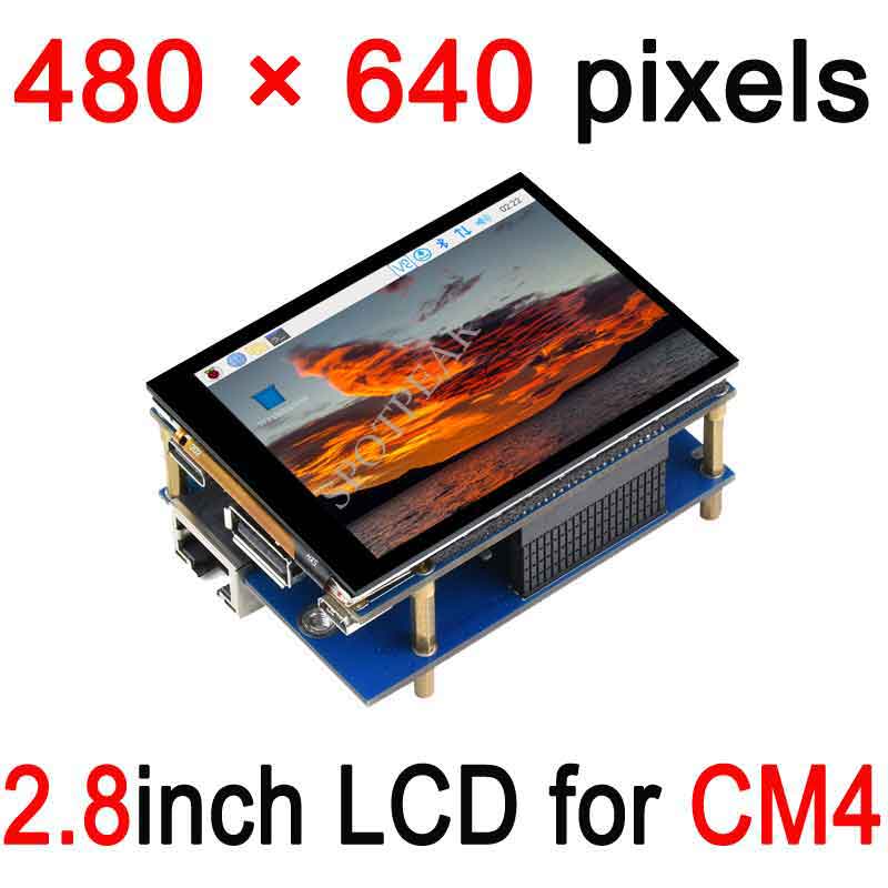
This product is a specially designed 2.8-inch CM4 touch screen expansion board for Raspberry Pi Compute Module 4. CM4-DISP-BASE-2.8A is a baseboard that can be used with Raspberry Pi Compute Module 4, using 5V/ 2.5A USB Type Powered by the C interface, it can be directly connected to the CM4 core board, equipped with a 2.8-inch IPS display, which can meet the operation of various versions of CM4, and supports camera and video output.
Notices
1: The display uses the DIP interface instead of the HDMI interface
2: Please use a 5V/4A or higher power adapter.
Dimensions
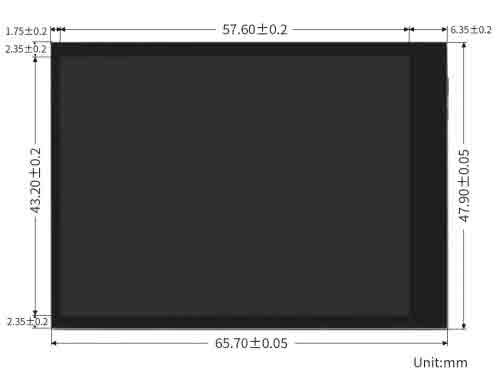
Touch Screen Expansion Board
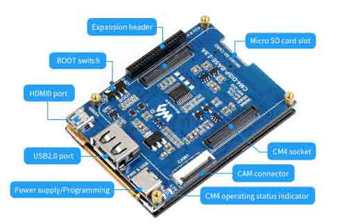
| CM4 Socket | suitable for all variants of Compute Module 4 |
|---|---|
| USB | USB 2.0 x1 |
| Connector | MIPI CSI 22PIN 0.5mm camera connector |
| Display | 2.8inch fully laminated screen, 480 x 640 pixels, 6-point capacitive touch, toughened glass panel |
| Video | micro HDMI x 1, supports 4K 30fps output |
| Storage | Micro SD card socket for Compute Module 4 Lite (without eMMC) variants |
| Power input | 5V |
Optional Interface Expander Introduction
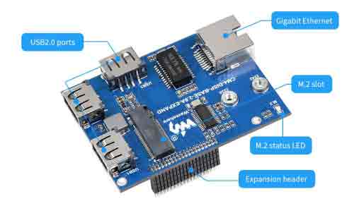
| Networking | Gigabit Ethernet RJ45 |
|---|---|
| USB | USB2.0 x3 |
Writing Image
- Write Image for Compute Module Boards eMMC version
- Wrote Image for Compute Module Boards Lite version
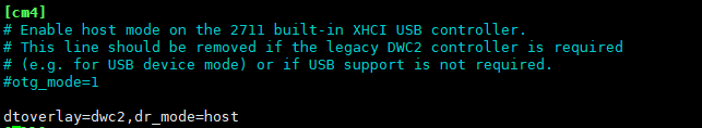
USB2.0
The USB port is disabled by default on the CM4 for saving power. If you need to use it, you need to add the following to the config.txt file:
dtoverlay=dwc2,dr_mode=host
Then reboot the CM4
If you use the latest Raspberry Pi OS (image after October 30, 2021) USB2.0 is OTG mode by default, CM4 will report an error:
config failed, hub doesn't have any ports! (err -19)
However, USB can still workable. If you want to remove this error, please remove the line otg_mode=1 in [cm4] of config.txt, and add dtoverlay=dwc2, dr_mode=host (USB cannot be recognized without adding it).
Display
For Raspberry Pi OS Bullseye batch
- Modify the config.txt file and append the following lines to the file:
dtoverlay=vc4-kms-v3d
dtoverlay=vc4-kms-DPI-28inch
dtoverlay=waveshare-28dpi-3b-4b
dtoverlay=waveshare-28dpi-3b
dtoverlay=waveshare-28dpi-4b
- Download the 2.8inch DPI LCD DTO file, unzip it and copyt the scripts to overlays directory (/boot/overlays)
For Raspberry Pi OS Bluster batch or Ubuntu
- Remove the line: dtoverlay=vc4-fkms-V3D from the config.txt file
- Add the following lines to the config.txt file
gpio=0-9=a2
gpio=12-17=a2
gpio=20-25=a2
dtoverlay=dpi24
enable_dpi_lcd=1
display_default_lcd=1
extra_transpose_buffer=2
dpi_group=2
dpi_mode=87
dpi_output_format=0x7F016
hdmi_timings=480 0 26 16 10 640 0 25 10 15 0 0 0 60 0 32000000 1
dtoverlay=waveshare-28dpi-3b-4b
dtoverlay=waveshare-28dpi-3b
dtoverlay=waveshare-28dpi-4b
- Restart your Raspberry Pi and test it
Orientation setting for Raspberry Pi OS
- Check if KMS or FKMS driver is enabled.
- You can check if dtoverly=vc4-kms-v3d or dtoverlya=vc4-fkms-v3d are added to config.txt file
- If the KMS/FKMS driver is enabled. You can set the orientation by the following command:
sudo nano /etc/xdg/lxsession/LXDE-pi/autostart
- Add the following line to the autostart file to rotate display, reboot is required
- 0: 0 degree; 1:270 degree;2: 180 degree; 3: 90 degree
xrandr -o 1
- If the KMS/FKMS driver is disabled, please use the following command to rotate display:
sudo nano /boot/config.txt
- Add the following line to config.txt file to rotate display, reboot is required
- 0: 0 degree; 1:90 degree;2: 180 degree; 3: 270 degree
display_rotate=3
M.2
The carrier board features M.2 KEY M interface for PCI-E devices like NVME SSD. SATA disk is not supported.
The device could support 2230, 2242 SSD, for some of the SSD, you may need to rebuild the kernel yourself.
.png)
Camera
If you use the buster system, you just need to add the configuration file and reboot.
If you use the new version (bullseye) system, additional modifications are required
Download script
wget https://www.waveshare.com/w/upload/a/a2/Dts-2.8A.zip
 unzip -o  Dts-2.8A.zip -d ./Dts-2.8A
 sudo chmod 777 -R Dts-2.8A
 cd Dts-2.8A/
 sudo  dtc -I dts -O dtb -o /boot/dt-blob.bin dt-blob-cm4-singlecam-dpi28.dts
Old Version (Buster)
Note: On December 2, 2021, the Raspberry Pi OS for Raspberry Pi split into two branches, the Buster branch, and the Bullseye branch.
The Buster branch is a continuation of the old system and is more stable. The Bullseye branch adds some new features, uses open source libraries and new interfaces.
If you use the Buster branch system, the image can be used normally without any modification. View the first connected camera screen:
sudo raspivid -t 0 -cs 0
New Version (Bullseye)
If you are using the Bullseye branch of the system, refer to the following
Camera
#Detect camera
libcamera-hello --list-cameras

#Preview
libcamera-hello  --camera 0

#Capture picture
libcamera-jpeg -o test.jpg
More instructions click me
Reference Raspberry Pi Manual