- sales/support
Google Chat:---
- sales
+86-0755-88291180
- sales01
sales@spotpear.com
- sales02
dragon_manager@163.com
- support
tech-support@spotpear.com
- CEO-Complaints
zhoujie@spotpear.com
- Only Tech-Support
WhatsApp:13246739196
- Purchase/Shipping/Refund
WhatsApp:13424403025
Raspberry Pi Compute Module PoE 4G Board User Guide
Instruction
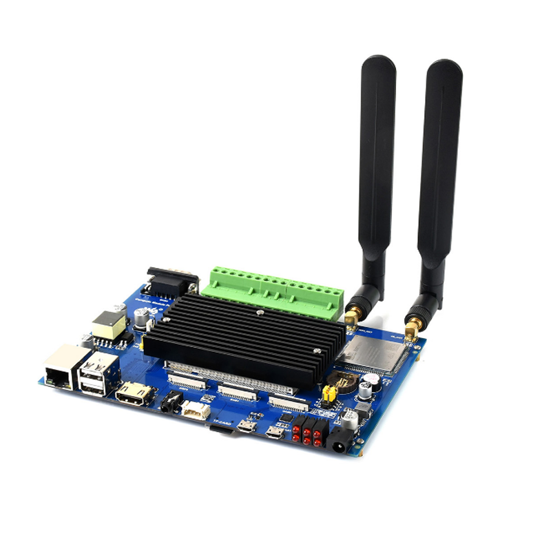
Compute Module PoE 4G Board is an industrial-grade host based on the Raspberry Pi compute module. It supports global communication 4G/3G/2G cellular, PoE Ethernet and WiFi and other network communication modes, and expands a variety of industrial isolated interface resources (such as CAN, RS485, RS232, ADC, GPIO, etc.), which is suitable for various industrial IoT applications.
Features
- Compatible with Raspberry Pi CM3 / CM3 Lite / CM3+ / CM3+ Lite.
- Onboard SIM7600X module, support 4G/3G/2G global communication (via onboard SIM card slot)
- Onboard 10/100M auto-negotiation Ethernet port, supports power via the PoE Ethernet interface(RJ45 interface specification)
- Supports 2.4GHz WiFi wireless connection.
- 1 × ADC port, screw terminal, isolated, 16-bit, 860SPS.
- 4 × GPIO ports, screw terminal, isolated, 2 channels as isolated input, 2 channels as isolated output.
- 1 × RS232 port, DR9 (male), isolated, with TVS protection, anti-surge, and ESD protection.
- 1 × RS485 port, screw terminal, isolated, with 600W lightning-proof, anti-surge, and 15KV ESD protection, allows using 120Ω terminal resistor.
- 1 × CAN interface, screw terminal, isolated, lightning-proof, and ESD protection, allows using 120Ω terminal resistor.
- Onboard USB HUB, allows connecting more USB devices
- Onboard USB TO UART, for serial debugging
- Audio interface: 1 ×3.5mm audio jack, stereo output
- Speaker interface: 1 ×4PIN speaker connector, supports 8Ω 5W speaker
- Onboard external RTC chip, with temperature sensor inside
- 2 × CSI camera interfaces,allows connecting the cameras.
- Onboard HDMI / DSI interfaces for connecting displays
- Industrial-grade aluminum alloy case
Onboard resources
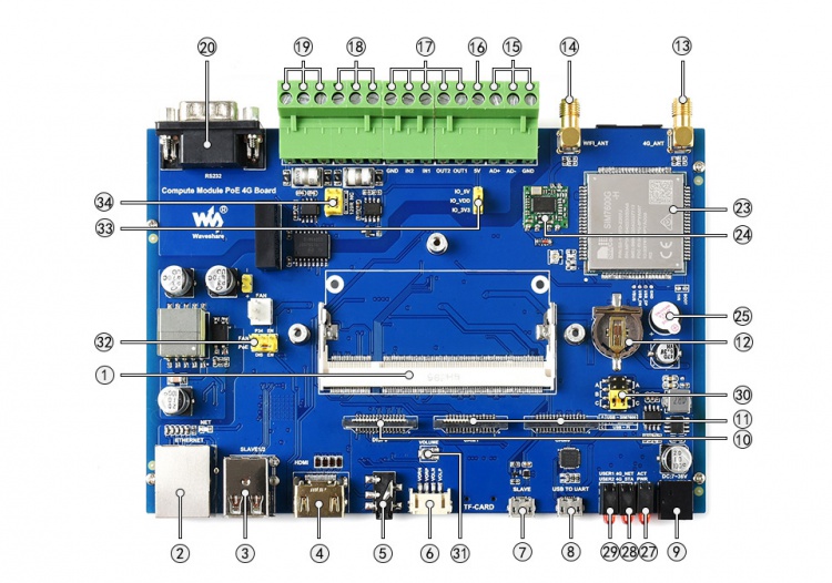
1: Compute Module socket for connecting Raspberry Pi Compute Module CM3 / CM3 Lite / CM3+ / CM3+ Lite
2: PoE enabled Ethernet port: 10/100M auto-negotiation, with PoE Power Over Ethernet features
3: USB Ports: allows connecting the USB device
4: HDMI Ports: allows connecting the HDMI device.
5: 3.5mm audio jack
6: Dual-channels speaker connector:allows connecting the speaker directly.
7: USB SLAVE: allows you to burn system image into CM3 or CM3+
8: USB TO UART for serial debugging
9: DC power input: supports 7-36V power supply
10: DSI display port for connecting Raspberry Pi LCD
11: CSI camera port for connecting Raspberry Pi Camera
12: RTC real time clock battery holder supports rechargeable Li cell ML1220
13: 4G antenna connector
14: WiFi antenna connector
15: Isolated ADC: ADC differential input
16: Isolated 5V power: max output current 100mA
17: Isolated GPIO: allows controlling / detecting devices via GPIO
18: Isolated RS485 interface: interface communication via RS485
19: Isolated CAN interface: interface communication via CAN
20: Isolated RS232 interface: interface communication via RS232
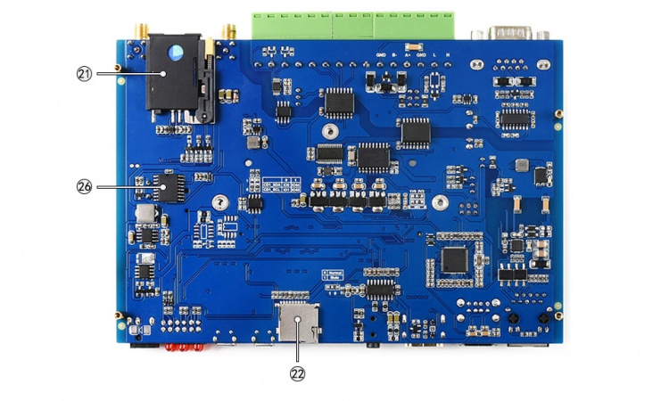
21: SIM slot: supports standard 4G/3G/2G SIM card
22: Micro SD card slot: insert a Micro SD card with pre-burnt system, to start up CM3 Lite / CM3+ Lite variant
23: SIM7600G-H communication module: supports 4G/3G/2G communication and GNSS function
24: WiFi module: supports 2.4G WiFi connection
25: Buzzer
26: DS3231: high precision RTC chip, I2C bus
27: Raspberry Pi indicator
ACT: Raspberry Pi operating status indicator
PWR: Raspberry Pi power indicator
28: SIM7600G-H indicator
NET: network indicator
STA: status indicator
29: User LED: handy for I/O output testing, or program running status monitoring
30: Serial port connection setting
31: Volume adjustment
32: PoE configuration
DIS: disable PoE
EN: enable PoE
33: ADC chip power supply selection
34: RS485 CAN terminal resistor selection