


- sales/support
Google Chat:---
- sales
+86-0755-88291180
- sales01
sales@spotpear.com
- sales02
dragon_manager@163.com
- support
tech-support@spotpear.com
- CEO-Complaints
zhoujie@spotpear.com
- Only Tech-Support
WhatsApp:13246739196
- Purchase/Shipping/Refund
WhatsApp:13424403025
- HOME
- >
- ARTICLES
- >
- Common Moudle
- >
- LCD
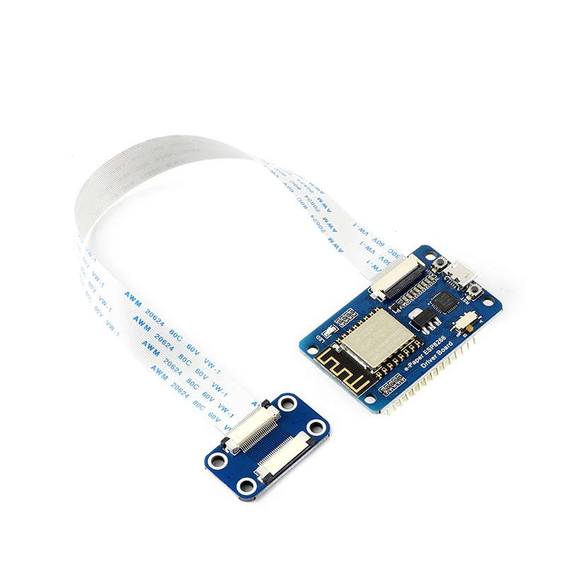
e-Paper ESP8266 Driver Board User Guide
Supported Models
This Wiki mainly introduces the specific operation of this product. If you want to obtain the ink screen models supported by this product, please go to the bottom of the official website for product details.
| Model | Demo |
| 1.54inch e-Paper | epd1in54_V2-demo |
| 1.54inch e-Paper (B) | epd1in54b_V2-demo |
| 2.13inch e-Paper | epd2in13_V3-demo |
| 2.13inch e-Paper (B) | epd2in13b_V4-demo |
| 2.13inch e-Paper (D) | epd2in13d-demo |
| 2.66inch e-Paper | epd2in66-demo |
| 2.66inch e-Paper (B) | epd2in66b-demo |
| 2.7inch e-Paper | epd2in7_V2-demo |
| 2.7inch e-Paper (B) | epd2in7b_V2-demo |
| 2.9inch e-Paper | epd2in9_V2-demo |
| 2.9inch e-Paper (B) | epd2in9b_V3-demo |
| 3.7inch e-Paper | epd3in7-demo |
| 4.01inch e-Paper (F) | epd4in01f-demo |
| 4.2inch e-Paper | epd4in2-demo |
| 4.2inch e-Paper (B) | epd4in2b_V2-demo |
| 4.26inch e-Paper | epd4in26-demo |
| 5.65inch e-Paper (F) | epd5in65f-demo |
| 5.83inch e-Paper | epd5in83_V2-demo |
| 5.83inch e-Paper (B) | epd5in83b_V2-demo |
| 7.5inch e-Paper | epd7in5_V2-demo |
| 7.5inch e-Paper (B) | epd7in5b_V2-demo |
| 13.3inch e-Paper (B) | epd13in13b-demo |
| 13.3inch e-Paper (K) | epd13in3k-demo |
Note: The corresponding demo only takes the latest version of the screen as an example, if you are using an older version, please refer to the version label on the back of the screen.
Introduction
E-Paper ESP8266 Driver Board can read pictures from a PC or phone by WiFi and display the information. It also supports Arduino.
Parameter
- WiFi standard: 802.11b/g/n
- Interface port: 3-wire SPI, 4-wire SPI (by default)
- Operating voltage: 5V
- Operating current: 50mA ~ 100mA
- Outline dimension: 29.57mm x 48.26mm
- Hole diameter: 2.9mm
Pin
| Pin | ESP8266 | Description |
| VCC | VCC | Power input (3.3V) |
| GND | GND | Ground |
| DIN | GPIO13 (D7) | SPI MOSI, data input |
| SCK | GPIO14 (D5) | SPI CLK, clock signal input |
| CS | GPIO15 (D8) | Chip selection, low active |
| DC | GPIO4 (D2) | Data/command, low for commands, high for data |
| RST | GPIO2 (D4) | Reset, low active |
| BUSY | GPIO5 (D1) | Bust status output pin (busy) |
PS: The above is a fixed connection of the board and does not require any additional operation from the user.
Feature
- Onboard ESP8266, support Arduino development.
- Provide HTML host computer program, can update content remotely through a web page, easy to integrate into various network applications.
- Supports Floyd-Steinberg's dithering algorithm for more color combinations and better shadow rendering of the original image.
- Supports a variety of common image formats (BMP, JPEG, GIF, PNG, etc.).
- Built-in e-Paper screen driver (open source).
- Comes with online complete supporting information manuals.
Application
This driver board works with the Waveshare e-Paper screen, which can be applied to the wireless update of electronic tags.
- Electronic price tags in supermarkets.
- Information labels for customer service windows, such as name labels.
- Small advertising label.
Preparation
Download examples
Two examples were provided for the display, the WiFi example and the offline example. You can find the file in #Resource, or directly click here to download.
Unzip the file and you will get the following examples:
- examples: Offline example
- Loader_esp32wf: WiFi Example
Setup Arduino IDE
- Arduino ESP32/8266 Online Installation
- Set up the model switch, and set the model switch according to the ink screen model used (if the display effect is poor or cannot be driven, please try to switch the switch)

| Trigger state | E-Paper |
| A | 1.54 inch, 2.13 inch, 2.9 inch |
| B | 1.54 inch(b), 2.13 inch(b), 2.7 inch, 2.7 inch(b), 2.9 inch(b), 4.2 inch, 4.2 inch (b), 7.5 inch(b), 7.5 inch(b) |
Image Process Algorithm
In the Bluetooth example and the WiFi example, we use two kinds of Image algorithms, Level and Dithering.
Level
An image can be divided into several large color gamuts. Each pixel on the image is classified into the corresponding color gamuts according to how close the color is to these color gamuts. This method is more suitable for images that have few colors, such as bright or three-color shapes or text images. Take the black, white, and red ink screen as an example. When processing the image, we hope to process it into black, white, and red. Therefore, for an image, we can divide all the colors of the image into three color areas: black area, white area, and red area.
For example, according to the figure below, if the value of a certain pixel in the grayscale image is equal to or less than 127, we regard this pixel as a black pixel, otherwise, it is white.
As we know, color images have three color channels called RGB. Compared with the red channel, we can collectively call blue and green the blue-green channel or the non-red channel. According to the figure below, if a pixel on a color image has a high red channel value but a low blue-green channel value, we classify it as a red pixel; if the value of both the red and blue-green channels are very low, we classify it as a black pixel; if the values of the red and blue-green channels are both high, we classify it as white.
In the algorithm, the color definition is calculated based on the difference between the RGB value and the sum of squares of the expected color value. The expected color value refers to the color value that the pixel is closest to, and these values are stored in the curPal array.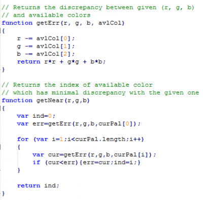
Dithering
For images with more colors or more gradient areas, the above color scale method is not suitable. In many cases, the pixels in the gradient area in the image may be very close to all color gamuts. If you use the Level method, the image will lose a lot of image details. Many pictures taken by cameras use the method of mixing colors to draw shadows and transition areas. In these images, the gradual area accounts for most of them.
For the human eye, it is easy to confuse very small colors. For example, set two colors red and blue side by side, if it is reduced to a small enough size, it will become a mixture color of red and blue to the human eye. The defect of the human eye means that we can deceive the human eye and use the "mixing" method to obtain more colors that can be expressed. The dithering algorithm uses this phenomenon.
The Floyd-Steinberg algorithm is based on the error diffusion method(published by Robert Floy and Louis Steinberg in 1976). The formula is based on the error diffusion of the image below:
X is the error (a scalar (vector) difference between the original color and the gray-scale value (the color value)), and the error spreads to the right, bottom right, bottom, and bottom left, adding weights of 7/16, 1/16, 5/16, and 3/16, respectively, to the values of the four pixels. If you are interested in the algorithm, you can search online for more resources.
Expected result of two methods
Original picture

"Black/White-Level" and "Colors-Level"


"Black/White-Dithering" and "Colors-Ditherring"


WiFi Demo
We provide WiFi demos with an HTML host computer.
Note: The module only supports the 2.4G network band.
How to Use
- Go to the Loader folder, and double-click the Loader.ino file to open the project.
- Select Tools -> Boards -> ESP8266 Boards -> NodeMCU 1.0, and select the corresponding serial port: Tools -> Port.

- Change the SSID and password in Loader. into the actual WiFi username and password.

- Press win + R and type CMD to open the command line and get the computer IP.

- Open the srvr.h file and change the network segment in the location shown in the picture to the corresponding network segment.

- Then click upload to compile and download the demo to the ESP8266 driver board.
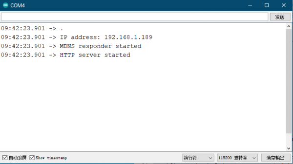
- Open the serial monitor, and set the baud rate to 115200, you can see the serial port will print out the IP address of the ESP8266 driver board as follows.
- Open the browser on your computer or cell phone (note that the network you are accessing needs to be on the same network segment as the wifi connected to the ESP8266), enter the IP address of the ESP8266 in the URL input field, and open it, you can see the operation interface as follows.

- The entire operation interface is divided into five areas:
- Image Operation Area:
Select Image file: Click to choose an image from your computer or phone.
Level: mono: Black and white image processing algorithm.
Level: color: Multi-color image processing algorithm (only effective for multi-color screens).
Dithering: mono: Black dithering image processing algorithm.
Dithering: color: Multi-color dithering image processing algorithm (only effective for multi-color screens).
Update image: Upload image. - IP information display area: This displays the IP address information of the module you are currently connected to.
- Image size setting area: Here, x and y can be set to specify the starting position of the display, which is relative to the image file you have selected. For example, if you choose an 800x480 image but the e-paper screen you are connected to is 2.9 inches, the screen will not be able to display the entire image. In this case, the processing algorithm will automatically crop the image from the upper left corner and send a portion of it to the e-paper screen for display. You can set x and y to customize the starting position of the cropping. W and h represent the resolution of the current e-paper screen. Note: If you modify the x and y coordinates, you need to click on the processing algorithm again to generate a new image.
- Model selection area: Here, you can choose the e-paper screen model you are connected to.
- Image display area: Here, the selected image and the processed image will be displayed.
- PS: During image upload, the upload progress will be displayed at the bottom.
- Image Operation Area:
- Area 1: Click "Select Image file" to choose an image, or drag and drop the image directly into the "Original image" area.
- Area 4: Choose the corresponding e-paper screen model, for example, 1.54b.
- Area 1: Click on an image processing algorithm, for example, "Dithering: color".
- Area 1: Click "Upload image" to upload the image to the e-paper screen display.

Offline Example
Provides Offline ESP8266-based demos without WiFi and other devices.
Demo Usage
- Open the Arduino IDE to view the project folder location (please do not modify it).


- Enter E-Paper_ESP8266_Driver_Board_Code\examples directory, and copy the entire esp8266-waveshare-epd folder to the libraries directory in the project folder.


- Close all Arduino IDE windows, and then reopen Arduino IDE, and choose the corresponding demo example.

- Choose the corresponding development board and the serial port.


Resources
Documentation
Demo Code
Software Driver
Related Resources
FAQ
Question:If you don't have a V2 logo on the back of your 2.13-inch e-paper screen, how do I use it?
- Open epd1in13.h in the project and change the following value to 1.

Question:Why does it keep prompting ERROR that the picture cannot be refreshed?
Try it with Google Chrome, if it still doesn't work, try another network.
Question:If you don't have a V2 logo on the back of your 1.54inch e-paper screen, how do I use it?
- Open epd1in54.h in the project and change the following value to 1.

Question:The wifi demo upload is normal, the serial port outputs the IP address, but the computer input IP address cannot be accessed, you need to check that the network segment of the IP is consistent with the network segment value of the wifi, and the IP does not conflict.
Modify the IP network segment, as shown in the following figure.
