- sales/support
Google Chat:---
- sales
+86-0755-88291180
- sales01
sales@spotpear.com
- sales02
dragon_manager@163.com
- support
tech-support@spotpear.com
- CEO-Complaints
zhoujie@spotpear.com
- sales/support
WhatsApp:13246739196
- HOME
- >
- ARTICLES
- >
- Common Moudle
- >
- ESP
General Driver for Robots User Guide
Open-source Demo
Circuit Diagram
Dimensions And Drawings
Model
Introduction
The multifunctional driver board specially designed for robots provides more possibilities for robots. Based on the ESP32-WROOM-32 module, Arduino IDE can be used for development, and it supports a variety of wireless communication methods, including WIFI, Bluetooth, and ESP-NOW.
Onboard versatile commonly used robot component interfaces, including DC motor interface with encoder, DC motor interface without encoder, bus servo interface, IIC interface, Lidar interface, PWM servo interface, SD card slot, etc.
A variety of resources are on board, which is convenient for robot project construction, including a 9-axis IMU, temperature sensor, automatic download circuit, Lidar serial port to USB circuit, bus servo control circuit, etc.
Features
- Based on the ESP32-WROOM-32 module, supports wireless communication methods such as WIFI, Bluetooth, and ESP-NOW.
- Onboard motor control interface for 2x DC motors with encoder or 4x DC motors (two groups) without encoder.
- Onboard serial bus servos control interface for controlling up to 253 ST3215 serial bus servos and obtaining servo feedback.
- Onboard 9-axis IMU can obtain attitude and heading information at any time.
- 7~13V voltage input can be powered directly by 2S or 3S lithium battery.
- Automatic download circuit for easy uploading demos.
- Support input voltage and current monitoring.
- Onboard TF card slot.
- Onboard Lidar interface and integrated UART to USB function.
- IIC interface for expanding other peripherals such as OLED, IMU, and other IIC communication protocols.
- Multi-functional extended interface, adapting to remaining interfaces for additional functions, such as controlling servos or relays.
- 40PIN extended header for connecting to Raspberry Pi, Jetson Nano, and other host computers, communicating via serial port or IIC, and powering the host computer.
- Provides open-source demos for onboard resources, and detailed tutorials for beginners to get started.
Parameters
| Main Controller | ESP32-WROOM-32 |
| Power Supply | DC 7-13V |
| Power Port | XH2.54 |
| Antenna Connector | IPEX1 |
| Download Interface | Type-C |
| Control Chip | ESP32 |
| Wireless Communication | WIFI, Bluetooth, ESP-NOW |
| Dimensions | 65 x 65mm |
| Mounting hole spacing | 49 x 58mm |
| Mounting hole diameter | 3mm |
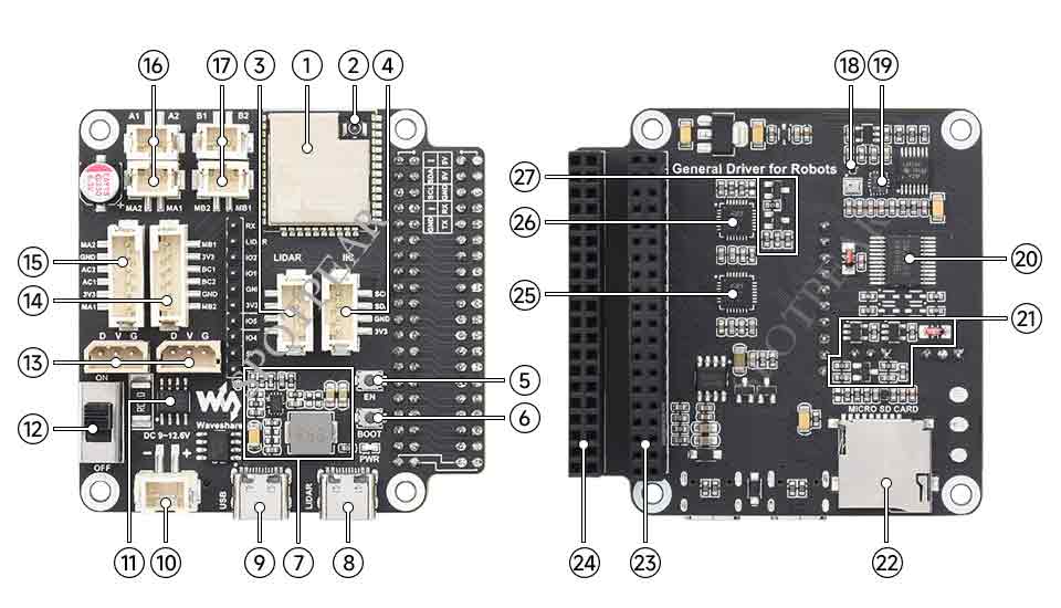
Onboard Resources

| No. | Onboard Resources | Introduction |
| 1 | ESP32-WROOM-32 main controller | Can be developed with the Arduino IDE |
| 2 | IPEX1 WiFi connector | For connecting the WIFI antenna to increase the wireless communication distance |
| 3 | LIDAR interface | Integrated radar adapter board function |
| 4 | IIC peripheral expansion interface | Can be used to connect OLED screens or other IIC sensors |
| 5 | Reset button | Press and release to reboot the ESP32 |
| 6 | Download button | The ESP32 will enter the download mode when the power is turned on by pressing |
| 7 | DC-DC 5V voltage regulator circuit | Power supply for host computers such as Raspberry Pi or Jetson nano |
| 8 | Type-C connector (LIDAR) | LIDAR data interface |
| 9 | Type-C connector (USB) | ESP32 UART communication interface, can upload programs for ESP32 |
| 10 | XH2.54 power port | Input DC 7~13V, this interface directly powers the serial bus servo and motor |
| 11 | INA219 | Voltage/current monitoring chip |
| 12 | Switches | Switches to control external power supply |
| 13 | ST3215 serial bus servo interface | For connecting to ST3215 serial bus servo |
| 14 | Motor interface PH2.0 6P | Group B interface for motor with encoder |
| 15 | Motor interface PH2.0 6P | Group A interface for motor with encoder |
| 16 | Motor interface PH2.0 2P | Group A interface for motor without encoder |
| 17 | Motor interface PH2.0 2P | Group B interface for motor without encoder |
| 18 | AK09918C | 3-axis electronic compass |
| 19 | QMI8658C | 6-axis motion sensor |
| 20 | TB6612FNG | Motor control chip |
| 21 | Serial bus servo control circuit | Can be used to expand multiple ST3215 serial bus servos and obtain servo feedback |
| 22 | SD card slot | Can be used to store logs or WIFI configurations |
| 23 | 40PIN extended header | Easy access to Raspberry Pi or Horizon Sunrise X3 Pi |
| 24 | 40PIN extended header | Easy to use the pins of the host computer installed on the driver board |
| 25 | CP2102 | UART to USB for radar data transfer |
| 26 | CP2102 | UART to USB for ESP32 UART communication |
| 27 | Automatic download circuit | Upload demos for the ESP32 without pressing the EN and BOOT buttons |
Main Usage
Onboard Rich Peripheral Interfaces For Driving Various Robots
- Crawler Robot
- Four-wheel drive UGV
- Two-wheel drive AGV
- Balance car
- Robotic arm
- Pan-tilt
Module Usage Tutorial
The above tutorial takes the complete demo of the UGV01 product as an example to explain how to use the Arduino IDE to upload the demo. You can replace the demo with the demo in the follow-up tutorial to the driver board.
- Tutorial I: Motor With Encoder Control Demo
- Tutorial II: Motor Without Encoder Control Demo
- Tutorial III: ST3215 Serial Bus Servo Control Demo
- Tutorial IV: PWM Servo Control Demo
- Tutorial V: IMU Data Reading Demo
- Tutorial VI: SD Card Reading Demo
- Tutorial VII: INA219 Voltage And Current Monitoring Demo
- Tutorial VIII: OLED Screen Control Demo
- Tutorial IX Lidar and Publishing Lidar Topics in ROS2


