




- sales/support
Google Chat:---
- sales
+86-0755-88291180
- sales01
sales@spotpear.com
- sales02
dragon_manager@163.com
- support
tech-support@spotpear.com
- CEO-Complaints
zhoujie@spotpear.com
- Only Tech-Support
WhatsApp:13246739196
- Purchase/Shipping/Refund
WhatsApp:13424403025
RP2350-ePaper-1.54 User Guide
Features
- Uses the RP2350A microcontroller chip developed by Raspberry Pi
- Unique dual-core, dual-architecture, featuring dual-core ARM Cortex-M33 processors and dual-core Hazard3 RISC-V processors, running at clock frequencies up to 150MHz, allowing users to flexibly switch between the two architectures
- Built-in 520KB of SRAM and 16MB of on-chip Flash
- Features a Type-C interface for easy plug-and-play (no orientation concerns)
- Features a 1.54inch e-Paper display, resolution 200 × 200, offering high contrast and wide viewing angles
- Supports USB1.1 host and device
- Supports low-power sleep and dormant modes
- Drag-and-drop programming using mass storage over USB
- 7 GPIO pins from RP2350A, USB+/- pins brought out
- 1 × I2C, 1 × UART, 6 × 12-bit ADC and 2 × controllable PWM channels
- Accurate on-chip clock and timer
- Built-in temperature sensor for real-time chip temperature monitoring
- 12 × programmable I/O (PIO) state machines for custom peripheral support
Onboard Resources
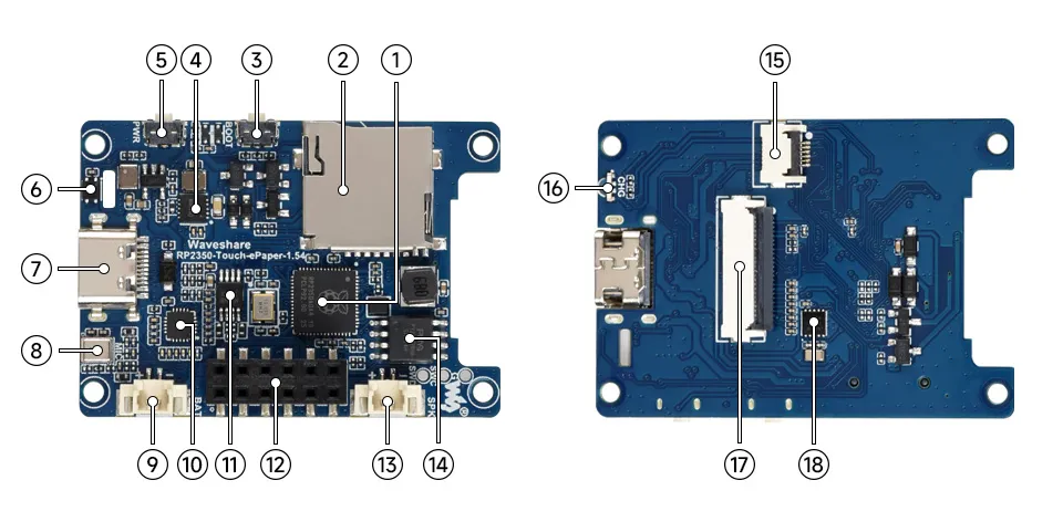
- RP2350 Dual-core, dual-architecture processor, operating frequency up to 150MHz
- TF Card Slot Supports TF card for expanded storage
- BOOT Button Press during reset to enter download mode
- Battery Charge/Discharge Management Chip For lithium battery management
- PWR Button For power control
- SHTC3 Temperature and Humidity Sensor Provides ambient temperature and humidity measurement, enabling environmental monitoring function
- USB Type-C Interface For program download, supports USB 1.1 host and device modes
- Microphone For audio capture
- MX1.25 Lithium Battery Interface For connecting a 3.7V lithium battery, supports charging and discharging, peak charging current 500mA
- ES8311 Low-power audio codec chip
- NS4150B Audio power amplifier chip
- 2 × 6PIN 2.54mm Pitch Female Header For connecting an external speaker
- MX1.25 Speaker Connector For connecting an external speaker
- 16MB NOR-Flash For storing programs and data
- Touch Panel Connector
- Dual-Color LED (Programmable LED + Charging Indicator LED)
- Display FPC Connector
- PCF85063 RTC clock chip, supports time-keeping function
Interface Introduction
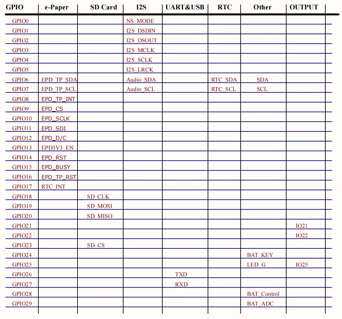
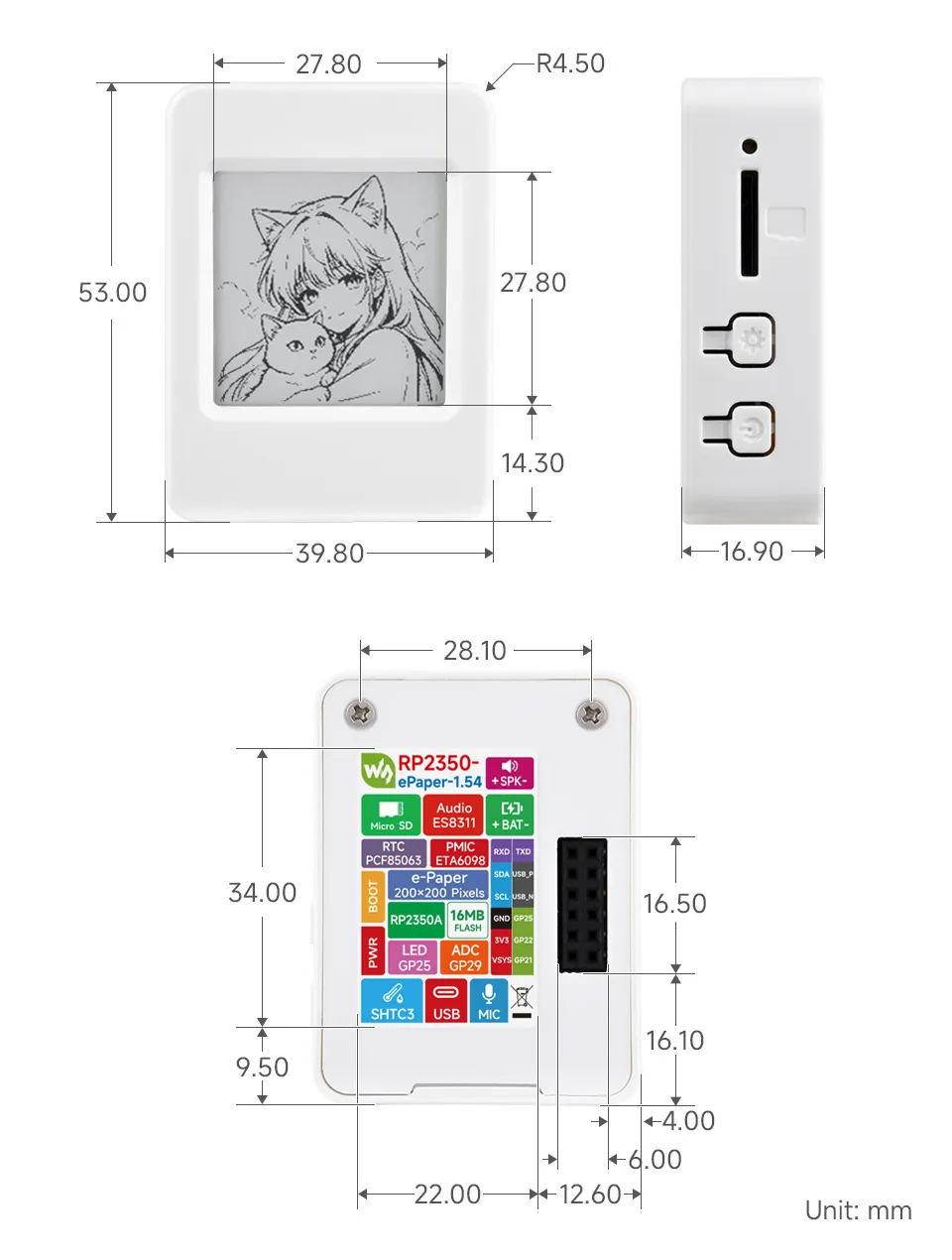
Dimensions
Working with MicroPython
This chapter contains the following sections. Please read as needed:
MicroPython Getting Started Tutorial
New to Pico MicroPython development and want to get started quickly? We have prepared a general introductory tutorial for you. These tutorial is designed to help developers quickly become familiar with Thonny IDE and start developing. It covers environment setup, project creation, component usage, and peripheral programming, helping you take the first step in MicroPython programming.
- Section 1 Basic Introduction
- Section 2 GPIO
- Section 3 PWM
- Section 4 ADC
- Section 5 UART
- Section 6 I2C
- Section 7 SPI
- Section 8 PIO
Setting Up the Development Environment
Please refer to the Install and Configure Thonny IDE Tutorial to download and install the Thonny IDE.
Example
The MicroPython examples are located in the examples\MicroPython directory of the example package.
| Example | Basic Program Description | Dependency Library |
|---|---|---|
| 01_SD | Mount TF card | - |
| 02_RTC | Get RTC data | - |
| 03_GUI | GUI display program | - |
| 04_KEY | Button test | - |
| 05_SHTC3 | Temperature and humidity sensor test | - |
| 06_TOUCH | Touch screen test | - |
| 07_ES8311 | ES8311 audio recording and playback test | - |
01_SD
Example Description
- Uses SPI to communicate with the TF card and mounts the TF card to the development board. After successful mounting, you can view and modify the contents of the TF card via Thonny.
Hardware Connection
- Insert a TF card
- Connect the board to the computer using a USB cable.
Code Analysis
sdcard.SDCard(spi, cs, baudrate): Creates a TF card object and binds the initialized SPI interface and CS pin to the TF card driver.uos.mount(sd, '/sd'): Mounts the TF card file system to the/sddirectory. After successful mounting, users can perform file read/write operations on the TF card via the/sdpath, such as creating, reading, or deleting files.
Operation Result
Upload all py files from the
01_SDfolder to the development board via Thonny and reset the board. After resetting, the development board will automatically mount the TF card to thesddirectory according to the boot.py program.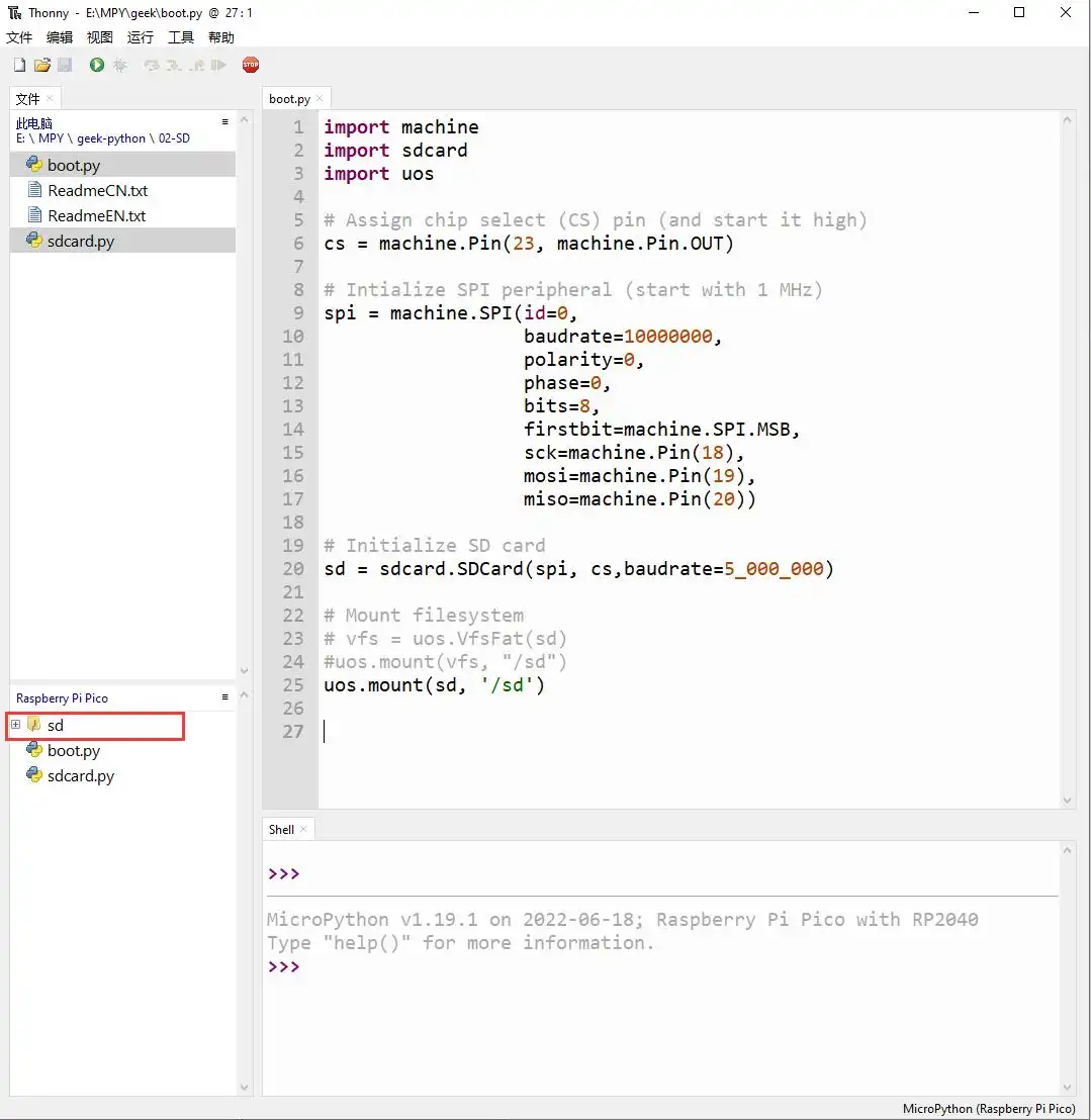
02_RTC
Example Description
- Uses I2C to communicate with the onboard RTC chip, sets and reads RTC time data, and tests if the RTC interrupt is functioning correctly.
Hardware Connection
- Connect the board to the computer using a USB cable.
Code Analysis
RTC = PCF85063(): Creates an RTC object.RTC.setDate(weekday, day, month, year): Sets the RTC date.RTC.setTime(hour, minute, second): Sets the RTC time.RTC.readTime(): Reads the RTC time.RTC.setAlarm(second, minute, hour, day, weekday): Sets the RTC alarm.RTC.enableAlarm(): Enables the RTC alarm.
Operation Result
Run the py files in the
02_RTCfolder using Thonny.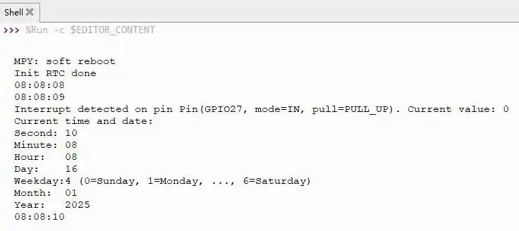
03_GUI
Example Description
- Drives the display via SPI communication, uses GUI drawing functions to draw text, borders, and color blocks, and refreshes the screen to complete the display.
Hardware Connection
- Connect the board to the computer using a USB cable.
Code Analysis
epd = EPD_1in54: Creates an LCD object.epd.Clear(0xff): Clears the entire screen.epd.fill(0xff): Fills the entire screen with a color.epd.text("RP2350-Touch-ePaper-1.54", 0, 30, 0x00): Writes text on the screen.epd.hline(10, 150, 80, 0x00): Draws a horizontal line.epd.vline(10, 90, 60, 0x00): Draws a vertical line.epd.display(epd.buffer): Refreshes the screen (makes it visible).
Operation Result
Run the py files in the
03_GUIfolder using Thonny.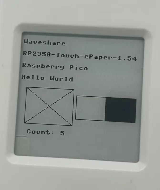
04_KEY
Example Description
- Demonstrates two-button input and common button event recognition under RP2350 MicroPython: BOOT (BOOTSEL special button) and POWER (regular GPIO24).
- Supported events:
down,up,click(single click),double(double click),long(long press), printing event logs to the serial port/Thonny Shell. - Example code file:
key_events.py(can be used as an importable library or run directly as a main script).
Hardware Connection
- BOOT: Use the onboard BOOTSEL button.
- POWER: Use the onboard POWER button (internally connected to GPIO24).
- Connect the board to the computer via a USB cable and connect the MicroPython interpreter via Thonny.
Code Analysis
BootKey: BOOTSEL read wrapper- BOOTSEL is not a regular GPIO; MicroPython generally provides a reading interface via
rp2.bootsel_button()(ormachine.bootsel_button()in some versions). pressed(): Returns whether the button is currently pressed (True means pressed).
- BOOTSEL is not a regular GPIO; MicroPython generally provides a reading interface via
GpioKey: Regular GPIO button read wrapperPin(pin, Pin.IN, pull): Configure the specified GPIO as input with pull-up/pull-down.active_low=True: Means pressed is 0, released is 1 (common configuration).
Key: Button event state machine (polling-based)debounce_ms: Debounce time. Only when the level change remains stable for longer than this time is the state considered truly changed.double_ms: Double-click detection window. A single-click event is only emitted after waiting fordouble_msto confirm no second click occurred.long_ms: Long press threshold. When pressed and held for longer thanlong_ms, alongevent is triggered immediately (without waiting for release).poll(now): Called periodically; internally:- Reads the raw level
- Debounces to obtain a stable state, sending
down/upon stable press/release - Long press detection: if stable press exceeds
long_ms, sendslong - Single/double click aggregation: on release, counts clicks; after timeout, converts 1 click to
click, 2 clicks todouble
main(banner=False, poll_ms=10): Program entry- When
banner=True, prints operation tips (suitable for guiding beginners when run as a main script). poll_msis the polling interval; smaller values are more responsive but consume more CPU (commonly 5–20ms).
- When
Operation Result
- Run the
.pyfiles in the04_KEYfolder directly via Thonny.- Open
key_events.pyin Thonny, ensure the interpreter is set to the MicroPython port of the development board. - Click the green Run button; Thonny will send the script to the board for execution.
- In this case, the script will run as
__main__, thus automatically enteringmain(banner=True), showing prompts and key event output. - If you want to use it as a library (import without automatic execution), upload the file to the board and explicitly call
key_events.main(...)in your ownmain.py.
- Open
- Run as main script (auto-execute on power-up)
- Upload
key_events.pyto the board root directory and rename it tomain.py. - After reset, it will first print banner information, then output events on key presses, e.g.:
power down/power up/power clickpower doublepower longboot down/boot up/boot click...
- Upload
- Run as reusable library (recommended)
- Keep the filename
key_events.pyunchanged and upload to the board. - Explicitly call in your own
main.py:import key_eventskey_events.main(banner=True)(orbanner=False)
- Keep the filename
- Stop running
Click the Stop button in Thonny, or press
Ctrl+Cin the Shell/REPL to end the polling loop and return to the interactive prompt.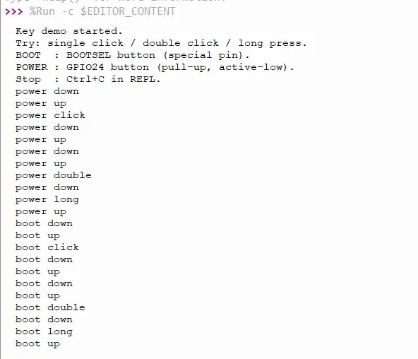
05_SHTC3
Example Description
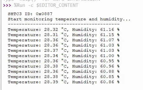
- Demonstrates reading the SHTC3 temperature and humidity sensor via I2C under RP2350 MicroPython.
- Supports reading:
- Temperature (°C)
- Relative humidity (%RH)
Hardware Connection
- Sensor is built-in: SHTC3 (I2C). I2C address: default
0x70 - Connect the board to the computer via a USB cable and connect the MicroPython interpreter via Thonny.
Code Analysis
Constants
I2C default parameters (see constants at the top of
shtc3.py):SHTC3_I2C_NUM: I2C controller numberSHTC3_I2C_SCL / SHTC3_I2C_SDA: Default pinsSHTC3_I2C_ADDR: I2C addressSHTC3_I2C_FREQ: I2C frequency
SHTC3 command set:
SHTC3_REG_WAKEUP / SHTC3_REG_SLEEP / SHTC3_REG_SOFTRESET / SHTC3_REG_READIDSHTC3_MEAS_ALL: Combinesstretch/low_power/hum_firstto select measurement command
SHTC3: Sensor driver class__init__(..., i2c=None, crc_fail_return=(None, None))i2c: Allows externally passing an already createdI2Cobject for sharing the bus with multiple devicescrc_fail_return: Return value when CRC check fails (default(None, None))- During initialization, executes:
wakeup(): Wake upsoft_reset(): Soft reset
crc8(buffer)- Used to verify CRC-8 returned by SHTC3 (polynomial
0x31, initial value0xFF)
- Used to verify CRC-8 returned by SHTC3 (polynomial
read_id()- Reads device ID and verifies CRC; returns
Noneif CRC fails
- Reads device ID and verifies CRC; returns
measurement(hum_first=False, low_power_meas=False, stretch=False, ...)- Reads temperature and humidity once and returns
(temperature_c, humidity_rh) - Parameter description:
low_power_meas=True: Low-power measurement (more power efficient, but repeatability/accuracy is slightly affected, more noticeable on temperature)stretch=True: Enable clock stretching (depends on your I2C bus/driver implementation)hum_first: Which of the two data blocks (temperature/humidity) comes first from the sensor
- Compatible parameter:
hum_frist: retains the typo for compatibility with older examples
- Reads temperature and humidity once and returns
read(low_power=False, stretch=False, ...)- More user-friendly alias: equivalent to
measurement(hum_first=False, ...)
- More user-friendly alias: equivalent to
main(...): Example entry (single-file integrated)When
shtc3.pyis run directly as a script, it will:- Execute
main(): loop reading and printing temperature/humidity Ctrl+Cto break the loop
- Execute
Parameter description:
interval_s: Print interval (seconds)crc_fail_return: Override the driver's default CRC failure return value
Operation Result
Method A: Run the
.pyfiles in the05_SHTC3folder directly via Thonny.Open
shtc3.pywith Thonny on your computer, and ensure the interpreter is set to the MicroPython port of the development board.Click Run; by default it enters
main(), with output similar to:SHTC3 ID: 0x....Temperature: 25.12 °C, Humidity: 45.67 %
Stop: Click Stop in Thonny, or press
Ctrl+Cin the REPL.Method B: Use as importable library (recommended)
- Upload
shtc3.pyto the board's file system (same directory asmain.pyis most convenient). - Use in your own
main.py:
import time
from shtc3 import SHTC3

shtc3 = SHTC3()
while True:
    t, rh = shtc3.read()
    if t is not None and rh is not None:
        print(t, rh)
    time.sleep(1)
06_TOUCH
Example Description
- This example is only for
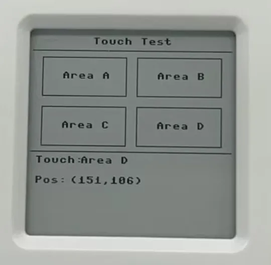
RP2350-Touch-ePaper-1.54. - This is a "touch test interface" example: draws 4 touch areas (Area A~D) on the 1.54inch 200×200 e-Paper screen. When touched, the coordinates and area name are displayed at the bottom of the screen and the touch coordinates are printed to the serial port.
- Screen display uses: first a full refresh to display the "base image", then switches to partial refresh mode for interactive updates (faster, saves time).
- The touch controller is FT6336U: reads touch point coordinates via I2C, triggers an interrupt via the INT pin to read data, and the main loop retrieves the touch point.
- Example code files:
- main.py
- FT6336U.py
Hardware Connection
- Connect the board to the computer via a USB cable and connect the MicroPython interpreter via Thonny.
Code Analysis
EPD_1in54: E-paper driver + FrameBuffer drawing wrapper (main.py)- Inherits
framebuf.FrameBuffer: usesbufferas a 200×200 monochrome canvas, then pushes the buffer to the screen. send_command()/send_data(): Write command/data to the screen controller via SPI.ReadBusy(): Poll the BUSY pin to wait for the screen to become idle (must wait during e-Paper refresh).displayPartBaseImage(): Writes the "base image" to both buffers (0x24/0x26) for more stable partial refresh (common practice to reduce ghosting).init(update): Two refresh mode initializationsFULL_UPDATE: Full refresh, slow but cleanPART_UPDATE: Partial refresh, fast but may have ghosting; requires base image coordination
- Inherits
touch_ft6336u: FT6336U touch driver (FT6336U.py)- I2C initialization (
__init__)machine.I2C(id=1, scl=Pin(7), sda=Pin(6), freq=400_000): Use I2C1, 400kHz.int = Pin(8, IN, PULL_UP): Touch interrupt pin, falling edge triggers callback.rst = Pin(16, OUT): Reset pin; pulls high/low at power-up to reset the chip.
init_chip(): Initialize and read ID- Read register
0xA3to get chip ID; example expects0x64, prints "init ok" or "ID error".
- Read register
- Interrupt reading of touch (
int_cb/read_touch_data)int_cb()triggersread_touch_data(), which first readsTD_STATUS(0x02)to get the number of touch points, then reads 4 bytes fromTOUCH1_X(0x03)to reconstruct x/y.- Supports single-touch: only Touch1 is parsed.
- Main loop point retrieval (
get_touch_xy)- Returns
[{"x":..., "y":...}]when new point is available, then clearspoint_countso a touch is taken only once (more like an "event" than continuous coordinate stream).
- Returns
- I2C initialization (
Main program flow (main.py)
- Initialize screen and clear screen:
epd = EPD_1in54(),epd.Clear(0xff)(0xff means white). - Initialize touch:
touch = touch_ft6336u(), will see FT6336U ID-related output on the serial port. - Draw static UI: title, dividing lines, 4 rectangular button areas (Area A~D), coordinate display area.
- Full refresh to show base image:
epd.displayPartBaseImage(epd.buffer), thenepd.init(epd.part_update)to switch to partial refresh mode. - Touch debounce and polling:
touch_debounce = 500: only respond to one touch within 500ms to avoid repeated triggers due to interrupts/jitter.touch.get_touch_xy(): when a touch point is obtained:- Update the coordinates and area name displayed at the bottom of the screen
- Highlight the corresponding area with "black background, white text"
displayPartial()for partial refresh- After 1 second, restore the button appearance and do another partial refresh
- Initialize screen and clear screen:
Operation Result
Method A: Run the
.pyfiles in the06_TOUCHfolder directly via Thonny.- Select the correct MicroPython interpreter port in Thonny.
- Upload
FT6336U.pyto the root directory of the RP2350's built-in MicroPython file system. - Open and run main.py.
- Serial port/Thonny Shell expected output includes:
Initializing e-Paper...Initializing touch screen...FT6336U ID = 0x64,FT6336U init ok!- On touch, prints:
Touch detected: (x, y)
- Screen expected display:
- "Touch Test" at the top
- 4 area buttons (Area A~D)
- Real-time update of
Touch:area name andPos:coordinates at the bottom
Method B: Run as power-on auto-start program
Upload
main.pyandFT6336U.pyto the root directory of the RP2350's built-in MicroPython file system.The program will run automatically after reset.
07_ES8311
Example Description
- Demonstrates driving the ES8311 audio Codec on RP2350 MicroPython: configure registers via I2C, transmit/receive audio data via I2S using PIO, and output MCLK using PIO; DMA is enabled when the firmware supports
rp2.DMA. - Reference default parameters (can be modified in
main.py):- Sample rate: 24 kHz (
SAMPLE_FREQ = 24000; supported sample rate combinations are determined by theCOEFF_DIVtable ines8311.py) - Bit width: ADC 16‑bit (
res_in=16), DAC 16‑bit (res_out=16) - Recording: mono int16 (PIO RX only collects one 16‑bit channel for easier DMA alignment and stability)
- Playback: can be configured as mono duplicated to stereo (example defaults to
channel_count = 2)
- Sample rate: 24 kHz (
- Example code files:
main.py: directly runnable loopback test (record and play)es8311.py: ES8311 I2C register driver (clock/format/volume/mute/microphone gain)audio_pio_mpy.py: PIO I2S + MCLK output (optional DMA interface)
Hardware Connection
- Connect the product to the computer via a Type‑C cable and connect Thonny to the MicroPython interpreter for testing and debugging.
Code Analysis
es8311.py: ES8311 register driver (I2C)write_reg()/read_reg(): single‑register write/read wrappers.COEFF_DIV+sample_frequency_config(mclk, rate): look up table to configure clock division based on MCLK and sample rate (example usesMCLK = SAMPLE_FREQ * 256).fmt_config(res_in, res_out): set I2S data width and operating mode (example uses I2S format and enables related mode bits).init(...): chip reset → clock configuration → format configuration → ADC/DAC related register initialization → set volume and microphone gain.volume_set()/volume_get(),mute(),microphone_gain_set(): common control interfaces.
audio_pio_mpy.py: PIO I2S transceiver + MCLK output (DMA optional)mclk_pio(): simplest square wave output, uses a StateMachine to generate MCLK.audio_pio_out(): waits for LRCLK/BCLK from ES8311, then outputs data synchronously; eachpull()takes a 32‑bit frame (left 16-bit + right 16-bit).audio_pio_in(): waits for LRCLK/BCLK, samples input data synchronously;autopush=True, push_thresh=16collects only one 16‑bit channel and pushes it into the RX FIFO.AudioPIO:mclk_pio_init()/dout_pio_init()/din_pio_init(): initialize each StateMachine and pin directions.audio_in_into(): polls samples from the RX FIFO (with timeout hints to help diagnose BCLK/LRCLK/DIN connections).dma_record_into()/dma_play_from_i16(): when the firmware supportsrp2.DMA, uses DMA to move data directly to/from PIO FIFOs, improving real‑time performance and reducing CPU load.
main.py: recording‑playback loopback example- Parameter section:
SAMPLE_FREQ,MCLK_FREQ,RECORD_DURATION_MS,DAC_VOLUME,MIC_GAIN,USE_DMA, etc. init_hardware(): enable the power amplifier control pin (PA_CTRL_PIN) and initialize I2C.init_es8311(): read Chip ID, callcodec.init(...), unmute.init_audio_pio(): configure PIO pins and StateMachine IDs (defaultSM_DOUT_ID=0,SM_DIN_ID=5,SM_MCLK_ID=2).- Main loop: record (DMA / non‑DMA) → print min/max/clipped →
condition_mic_samples()DC removal and attenuation → play (DMA / non‑DMA).
- Parameter section:
Operation Result
- Run via Thonny
- Upload all .py files in the
07_ES8311folder to the device root directory using Thonny. - Open
main.pyin Thonny on your computer and click Run. - When running normally, the serial port will print I2C scan results, ES8311 Chip ID, and statistics for each loopback cycle (cycle count, recording duration, min/max, clipped, etc.).
- Upload all .py files in the
- Upload and run on device
- Upload all .py files in the
07_ES8311folder to the device root directory using Thonny. - Reset / power‑cycle the device; it will automatically execute
main.pyin the root directory (ensure all 3 files are uploaded:main.py,es8311.py,audio_pio_mpy.py).
- Upload all .py files in the
- Stop execution
Click the Stop button in Thonny, or press
Ctrl+Cin the Shell/REPL to exit the loop and return to the interactive prompt.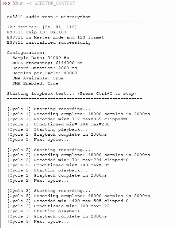
Working with C/C++
This chapter contains the following sections. Please read as needed:
Setting Up Development Environment
Please refer to the Install and Configure Pico C/C++ Development Environment Tutorial to download and install the Pico VSCode.
Example
The C/C++ examples are located in the examples\C directory of the example package.
| Example | Basic Program Description | Dependency Library |
|---|---|---|
| 01_FatFs | FAT file system, TF card supports SPI/SDIO communication | - |
| 02_ES8311 | Development board audio test program | - |
| 03_GUI | GUI display program | - |
| 04_LVGL | LVGL display program | LVGL V8.4 |
01_FatFs
Example Description
- Uses SPI or PIO-emulated SDIO to communicate with the TF card, implementing a command-line interface similar to busybox or DOS.
Hardware Connection
- Insert a TF card
- Connect the board to the computer using a USB cable
Code Analysis
sd_init_driver(): Initializes the TF card driver.getchar_timeout_us(): Gets UART input.process_stdio(): Processes UART input.
Operation Result
Use a terminal tool like putty or mobaxterm to open the corresponding USB serial port of the development board.
Press the Enter key to start the command-line interface (CLI). You should see a prompt similar to this:
>Enter help command to get the available commands as follows
> helpsetrtc <DD> <MM> <YY> <hh> <mm> <ss>:Set Real Time ClockParameters: new date (DD MM YY) new time in 24-hour format (hh mm ss)e.g.:setrtc 16 3 21 0 4 0date:Print current date and timelliot <drive#>:!DESTRUCTIVE! Low Level I/O Driver Teste.g.: lliot 1format [<drive#:>]:Creates an FAT/exFAT volume on the logical drive.e.g.: format 0:mount [<drive#:>]:Register the work area of the volumee.g.: mount 0:unmount <drive#:>:Unregister the work area of the volumechdrive <drive#:>:Changes the current directory of the logical drive.<path> Specifies the directory to be set as current directory.e.g.: chdrive 1:getfree [<drive#:>]:Print the free space on drivecd <path>:Changes the current directory of the logical drive.<path> Specifies the directory to be set as current directory.e.g.: cd 1:/dir1mkdir <path>:Make a new directory.<path> Specifies the name of the directory to be created.e.g.: mkdir /dir1ls:List directorycat <filename>:Type file contentssimple:Run simple FS testsbig_file_test <pathname> <size in bytes> <seed>:Writes random data to file <pathname>.<size in bytes> must be multiple of 512.e.g.: big_file_test bf 1048576 1or: big_file_test big3G-3 0xC0000000 3cdef:Create Disk and Example FilesExpects card to be already formatted and mountedstart_logger:Start Data Log Demostop_logger:Stop Data Log Demo
02_ES8311
Example Description
- Uses PIO-emulated I2S to communicate with ES8311, enabling audio input and output.
Hardware Connection
- Connect the speaker
- Connect the board to the computer using a USB cable
Code Analysis
Es8311_Init(): Initializes ES8311.Es8311_Sample_Frequency_Config(): Configures sampling rate.Es8311_Microphone_Config(): Configures the microphone.Es8311_Microphone_Gain_Set(): Sets microphone gain.Es8311_Voice_Volume_Set(): Sets volume.Sine_440hz_Out(): Outputs a 440 Hz sine wave.Happy_Birthday_Out(): Outputs a 440 Hz sine wave.Loopback_Test(): Audio recording and playback test.Music_Out(): Plays music.
Operation Result
- Use VS Code to import and compile the 02_ES8311 project. After compilation is complete, flash the uf2 file in the
builddirectory, or directly flash the uf2 file in the02_ES8311\uf2directory for quick verification.
03_GUI
Example Description
- Uses SPI to communicate with the display, and implements functions such as displaying text and images via GUI.
Hardware Connection
- Connect the board to the computer using a USB cable
Code Analysis
Underlying Hardware Interface
We have encapsulated the hardware operations at a low level. Due to differences in hardware platforms, the internal implementations vary. If you need to understand the internal implementation, you can check the corresponding directory. Many definitions can be seen in DEV_Config.c(.h) under the directory: lib\Config.
Module initialization and exit handling
void DEV_Module_Init(void);void DEV_Module_Exit(void);TIPThis handles certain GPIO operations before using the display and after finishing.
GPIO read/write
void DEV_Digital_Write(uint_16 Pin, uint_8 Value);uint_8 DEV_Digital_Read(uint_16 Pin);SPI write data
void DEV_SPI_WriteByte(uint_8 Value);
Upper Layer Applications
For the screen, what if you need to paint, display Chinese and English characters, display pictures, etc., these are all done by the upper layer applications. Many users have asked about graphical processing. We provide some basic functionalities in the GUI, located in the directory: lib\GUI\GUI_Paint.c(.h).

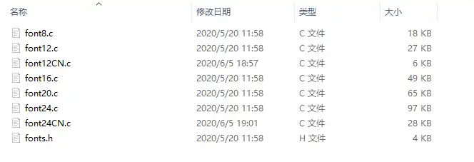
The character fonts that the GUI depends on are located in the directory: lib\Fonts.
Create Image Attribute: Create a new image attribute, which includes the name, width, height, rotation angle, and color of the image cache.
void Paint_NewImage(uint16_t *image, uint16_t Width, uint16_t Height, uint16_t Rotate, uint16_t Color)Parameters:image: The name of the image cache, which is essentially a pointer to the starting address of the image cache;Width: The width of the image cache;Height: The height of image cache;Rotate: The rotation angle of the image;Color: The initial color of the image;Select Image Cache: Selects an image cache. The purpose of this selection is to allow you to create multiple image attributes. Since multiple image caches can exist, you can select each image you have created.
void Paint_SelectImage(uint8_t *image)Parameters:image: The name of the image cache, which is essentially a pointer to the starting address of the image cache;Image Rotation: Set the rotation angle for the selected image. It is best to use this after
Paint_SelectImage(). You can choose rotation angles of 0, 90, 180, or 270 degrees.void Paint_SetRotate(uint16_t Rotate)Parameters:Rotate: The image rotation angle. You can choose ROTATE_0, ROTATE_90, ROTATE_180, ROTATE_270 corresponding to 0, 90, 180, 270 degrees respectively.TIPThe starting pixel for coordinates differs under different rotation angles. Taking 1.14 as an example, the four images correspond to 0°, 90°, 180°, and 270° in order. This is for reference only.
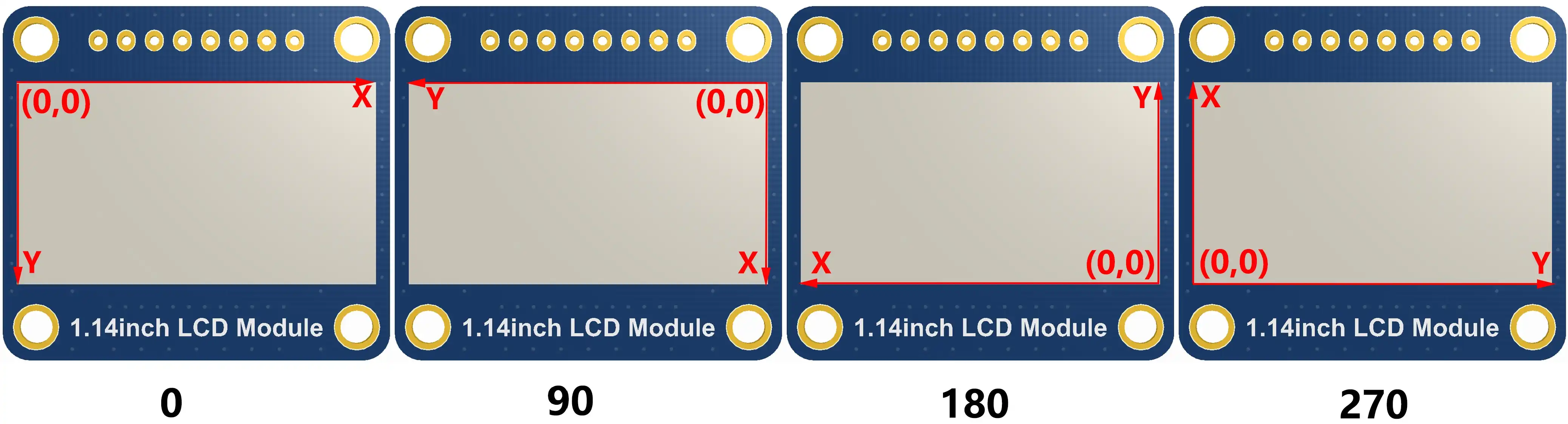
Image Mirroring: Set mirroring for the selected image. You can choose no mirroring, horizontal mirroring, vertical mirroring, or mirroring about the image center.
void Paint_SetMirroring(uint8_t mirror)Parameters:mirror: The mirroring method for the image. You can choose MIRROR_NONE, MIRROR_HORIZONTAL, MIRROR_VERTICAL, MIRROR_ORIGIN corresponding to no mirroring, horizontal mirroring, vertical mirroring, and mirroring about the image center respectively.Set Pixel Display Position and Color in Cache: This is one of the core GUI functions, handling the display position and color of a pixel within the cache.
void Paint_SetPixel(uint16_t Xpoint, uint16_t Ypoint, uint16_t Color)Parameters:Xpoint: The X-coordinate of the point within the image cache;Ypoint: The Y-coordinate of the point within the image cache;Color: The display color of the point;Fill Image Cache with Color: Fills the image cache with a specific color, typically used to clear the screen to white.
void Paint_Clear(uint16_t Color)Parameters:Color: The filled colorFill Partial Window in Image Cache with Color: Fill a specific window area within the image cache with a color, often used to clear a window to white, such as when updating time displays to clear the previous second.
void Paint_ClearWindows(uint16_t Xstart, uint16_t Ystart, uint16_t Xend, uint16_t Yend, uint16_t Color)Parameters:Xstart: The X starting coordinate of the window;Ystart: The Y starting coordinate of the window;Xend: The X ending coordinate of the window;Yend: The Y ending coordinate of the window;Color: The filled colorDraw Dot: Draw a dot at (Xpoint, Ypoint) in the image cache. You can choose the color, the size, and the style of the dot.
void Paint_DrawPoint(uint16_t Xpoint, uint16_t Ypoint, uint16_t Color, DOT_PIXEL Dot_Pixel, DOT_STYLE Dot_Style)Parameters:Xpoint: The X-coordinate of the dot;Ypoint: The Y-coordinate of the dot;Color: The filled colorDot_Pixel: The size of the dot, with 8 default sizes provided:typedef enum {DOT_PIXEL_1X1 = 1, // 1 x 1DOT_PIXEL_2X2 , // 2 X 2DOT_PIXEL_3X3 , // 3 X 3DOT_PIXEL_4X4 , // 4 X 4DOT_PIXEL_5X5 , // 5 X 5DOT_PIXEL_6X6 , // 6 X 6DOT_PIXEL_7X7 , // 7 X 7DOT_PIXEL_8X8 , // 8 X 8} DOT_PIXEL;Dot_Style: The style of the dot, defining the method to expand the size of the dot is that, whether to expand from the dot as the center or from the dot as the lower left corner to the upper right.typedef enum {DOT_FILL_AROUND = 1,DOT_FILL_RIGHTUP,} DOT_STYLE;Draw Line: Draw a line from (Xstart, Ystart) to (Xend, Yend) in the image cache. You can select the color, line width, and line style.
void Paint_DrawLine(uint16_t Xstart, uint16_t Ystart, uint16_t Xend, uint16_t Yend, uint16_t Color, LINE_STYLE Line_Style , LINE_STYLE Line_Style)Parameters:Xstart: The X starting coordinate of the line;Ystart: The Y starting coordinate of the line;Xend: The X ending coordinate of the line;Yend: The Y ending coordinate of the line;Color: The filled colorLine_width: The width of the line, with 8 default widths provided:typedef enum {DOT_PIXEL_1X1 = 1, // 1 x 1DOT_PIXEL_2X2 , // 2 X 2DOT_PIXEL_3X3 , // 3 X 3DOT_PIXEL_4X4 , // 4 X 4DOT_PIXEL_5X5 , // 5 X 5DOT_PIXEL_6X6 , // 6 X 6DOT_PIXEL_7X7 , // 7 X 7DOT_PIXEL_8X8 , // 8 X 8} DOT_PIXEL;Line_Style: The line style, choosing between solid line connection or dotted line connectiontypedef enum {LINE_STYLE_SOLID = 0,LINE_STYLE_DOTTED,} LINE_STYLE;Draw Rectangle: Draw a rectangle from (Xstart, Ystart) to (Xend, Yend) in the image cache. You can select the color, line width, and whether to fill the interior of the rectangle.
void Paint_DrawRectangle(uint16_t Xstart, uint16_t Ystart, uint16_t Xend, uint16_t Yend, uint16_t Color, DOT_PIXEL Line_width, DRAW_FILL Draw_Fill)Parameters:Xstart: The X starting coordinate of the rectangle;Ystart: The Y starting coordinate of the rectangle;Xend: The X ending coordinate of the rectangle;Yend: The Y ending coordinate of the rectangle;Color: The filled colorLine_width: The width of the rectangle's four sides, with 8 default widths provided:typedef enum {DOT_PIXEL_1X1 = 1, // 1 x 1DOT_PIXEL_2X2 , // 2 X 2DOT_PIXEL_3X3 , // 3 X 3DOT_PIXEL_4X4 , // 4 X 4DOT_PIXEL_5X5 , // 5 X 5DOT_PIXEL_6X6 , // 6 X 6DOT_PIXEL_7X7 , // 7 X 7DOT_PIXEL_8X8 , // 8 X 8} DOT_PIXEL;Draw_Fill: Fill option, determining whether to fill the interior of the rectangle:typedef enum {DRAW_FILL_EMPTY = 0,DRAW_FILL_FULL,} DRAW_FILL;Draw Circle: Draw a circle with center at (X_Center, Y_Center) and a radius of Radius in the image cache, and you can choose the color. You can select the color, line width, and whether to fill the interior of the circle.
void Paint_DrawCircle(uint16_t X_Center, uint16_t Y_Center, uint16_t Radius, uint16_t Color, DOT_PIXEL Line_width, DRAW_FILL Draw_Fill)Parameters:X_Center: The X-coordinate of the circle's center;Y_Center: The Y-coordinate of the circle's center;Radius: The radius of the circle;Color: The filled colorLine_width: The width of the circle's arc, with 8 default widths provided:typedef enum {DOT_PIXEL_1X1 = 1, // 1 x 1DOT_PIXEL_2X2 , // 2 X 2DOT_PIXEL_3X3 , // 3 X 3DOT_PIXEL_4X4 , // 4 X 4DOT_PIXEL_5X5 , // 5 X 5DOT_PIXEL_6X6 , // 6 X 6DOT_PIXEL_7X7 , // 7 X 7DOT_PIXEL_8X8 , // 8 X 8} DOT_PIXEL;Draw_Fill: Fill option, determining whether to fill the interior of the circle:typedef enum {DRAW_FILL_EMPTY = 0,DRAW_FILL_FULL,} DRAW_FILL;Draw Ascii Character: Draw an Ascii character in the image cache with (Xstart, Ystart) as the top-left vertex. You can select the Ascii visible character font, foreground color, and background color.
void Paint_DrawChar(uint16_t Xstart, uint16_t Ystart, const uint8_t Ascii_Char, sFONT* Font, uint16_t Color_Foreground, uint16_t Color_Background)Parameters:Xstart: The X-coordinate of the number's top-left vertex;Ystart: The Y-coordinate of the number's top-left vertex;Ascii_Char: The Ascii character;Font: The Ascii visible character font. The following fonts are provided in the Fonts folder:font8: 5*8 fontfont12: 7*12 fontfont16: 11*16 fontfont20: 14*20 fontfont24: 17*24 fontColor_Foreground: The font color;Color_Background: The background color;Draw English String: Draw a string of English characters in the image cache with (Xstart, Ystart) as the top-left vertex. You can select the Ascii visible character font, foreground color, and background color.
void Paint_DrawString_EN(uint16_t Xstart, uint16_t Ystart, const uint8_t * pString, sFONT* Font, uint16_t Color_Foreground, uint16_t Color_Background)Parameters:Xstart: The X-coordinate of the number's top-left vertex;Ystart: The Y-coordinate of the number's top-left vertex;pString: The string, which is a pointer;Font: The Ascii visible character font. The following fonts are provided in the Fonts folder:font8: 5*8 fontfont12: 7*12 fontfont16: 11*16 fontfont20: 14*20 fontfont24: 17*24 fontColor_Foreground: The font color;Color_Background: The background color;Draw Chinese String: Draw a string of Chinese characters in the image cache with (Xstart, Ystart) as the top-left vertex. You can select the GB2312 encoded character font, foreground color, and background color.
void Paint_DrawString_CN(uint16_t Xstart, uint16_t Ystart, const uint8_t * pString, cFONT* font, uint16_t Color_Foreground, uint16_t Color_Background)Parameters:Xstart: The X-coordinate of the number's top-left vertex;Ystart: The Y-coordinate of the number's top-left vertex;pString: The string, which is a pointer;Font: The GB2312 encoded character font. The following fonts are provided in the Fonts folder:font12CN: Ascii character 11*21 font, Chinese 16*21 fontfont24CN: Ascii character 24*41 font, Chinese 32*41 fontColor_Foreground: The font color;Color_Background: The background color;Draw Number: Draw a number string in the image cache with (Xstart, Ystart) as the top-left vertex. You can select the Ascii visible character font, foreground color, background color, and decimal places.
void Paint_DrawNum(uint16_t Xpoint, uint16_t Ypoint, uint32_t Nummber, sFONT* Font, uint16_t Digit,uint16_t Color_Foreground, uint16_t Color_Background);Parameters:Xstart: The X-coordinate of the number's top-left vertex;Ystart: The Y-coordinate of the number's top-left vertex;Number: The displayed number, here is stored in a 32-bit long int type, which can be displayed up to 2147483647.Font: The Ascii visible character font. The following fonts are provided in the Fonts folder:font8: 5*8 fontfont12: 7*12 fontfont16: 11*16 fontfont20: 14*20 fontfont24: 17*24 fontDigit: The number of decimal places to displayColor_Foreground: The font color;Color_Background: The background color;Display Time: Display a time period in the image cache with (Xstart, Ystart) as the top-left vertex. You can select the Ascii visible character font, foreground color, and background color.
void Paint_DrawTime(uint16_t Xstart, uint16_t Ystart, PAINT_TIME *pTime, sFONT* Font, uint16_t Color_Background, uint16_t Color_Foreground)Parameters:Xstart: The X-coordinate of the number's top-left vertex;Ystart: The Y-coordinate of the number's top-left vertex;pTime: The time to display, using a predefined time structure; simply pass the hour, minute, and second digits to the parameters;Font: The Ascii visible character font. The following fonts are provided in the Fonts folder:font8: 5*8 fontfont12: 7*12 fontfont16: 11*16 fontfont20: 14*20 fontfont24: 17*24 fontColor_Foreground: The font color;Color_Background: The background color;
Operation Result
- Import and compile the 03_GUI project using VS Code. After compilation, flash the .uf2 file from the
builddirectory, or directly flash 03_GUI.uf2 from thefirmware\Cdirectory for quick verification.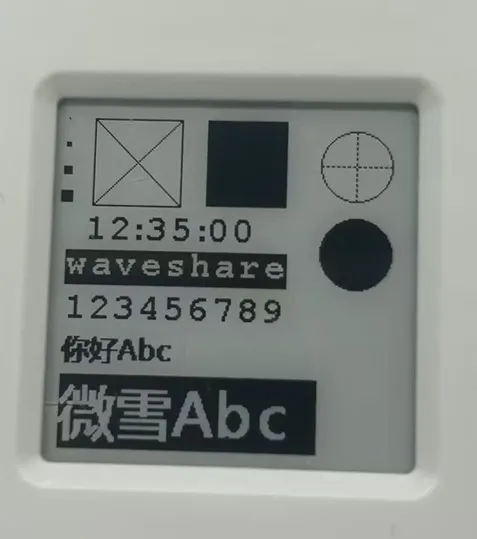
04_LVGL
Example Description
- Uses SPI to communicate with the display, and implements functions such as displaying text and images via LVGL.
Hardware Connection
- Connect the board to the computer using a USB cable
Code Analysis
Source Code Structure
The source code of the LVGL library is located in
lib\lvglof the project folder, version 8.4. For secondary development, please refer to the corresponding version's development documentation.LVGL library related settings are in
examples\inc\lv_conf.hof the project folder, where you can set display refresh rate, system data usage, etc.The application code for the LVGL library is located in
main.c,lv_port\lv_port_disp.c, andlv_port\lv_port_indev.cin the project folder.
LVGL Initialization
Before using the LVGL graphics library, you need to initialize LVGL.
LVGL Library Initialization Function
Code location:
main.cFunction: Mainly used to initialize the hardware and structure variables required by LVGL.
LVGL_Init();LVGL Core Initialization
Code location:
main.c/*2.Init LVGL core*/lv_init();
LVGL Run
The LVGL library periodically calls the heartbeat interface function lv_tick_inc to notify LVGL of the elapsed time, allowing LVGL to update its internal time state and handle time-related tasks such as animations, timers, and more. In the main function loop, the lv_task_handler function must also be called so that LVGL can process events and tasks in a timely manner, ensuring the responsiveness and refresh of the user interface.
LVGL heartbeat interface
Code location:
main.cImplementation: Ensure the priority of
lv_task_handleris lower than that oflv_tick_inc. In this example,lv_tick_incis called in the timer callback function.//Timer callback function is called every 5msadd_repeating_timer_ms(5, repeating_lvgl_timer_callback, NULL, &lvgl_timer);static bool repeating_lvgl_timer_callback(struct repeating_timer *t){lv_tick_inc(5);return true;}LVGL task handler
Location:
examples\src\LCD_XinXX_LVGL_test.cImplementation: To handle LVGL tasks,
lv_timer_handler()needs to be called periodically. In this example, it's called in the main function loop.int main(){...while (1){lv_task_handler();DEV_Delay_ms(5);...}}
LVGL Display
To enable LVGL display, a display driver must be initialized and its various properties configured, such as color format, draw buffer, rendering mode, and display callback function. At each LV_DISP_DEF_REFR_PERIOD (set in lv_conf.h), LVGL detects if something has happened on the UI that needs to be redrawn. For example, a button is pressed, a chart is changed, an animation occurs, etc. When redrawing is needed, LVGL calls the display callback function to complete the drawing of the image in the refresh area.
LVGL Display Refresh Rate Setting
Location:
examples\inc\lv_conf.hSetting: You can also set the refresh period time for the display buffer in
lv_conf.h. Modify this definition to change the screen refresh time.#define LV_DISP_DEF_REFR_PERIOD 10 // Unit: ms, here is 10msLVGL Display Color Setting
Location:
examples\inc\lv_conf.hPurpose: Since the pixel color storage method constructed by the
lv_color_tstructure by default is inconsistent with the data format required for transmission in this example, direct transmission would cause color differences in the displayed image.#define LV_COLOR_16_SWAP 1LVGL display-related variable definitions
Code location:
lv_port\lv_port_disp.cFunction: Defines the display driver
disp_drvand the draw bufferdisp_buf. In this example, the draw bufferbuf0is set to the entire screen display area, which effectively improves the screen refresh rate while reducing aliasing during large-area screen refreshes.static lv_disp_drv_t disp_drv;static lv_disp_draw_buf_t disp_buf;static lv_color_t *buf0;LVGL display device registration
Code location:
lv_port\lv_port_disp.cFunction: according to design requirements, complete the core structure variables of the LVGL library, initialize the display driver
disp_drv, and set the draw buffers. The draw buffers are simple arrays used by LVGL to render screen content. Once rendering is ready, the content of the draw buffer is sent to the display using thedisp_drv_flush_cbfunction set in the display driver.static UBYTE img[(((EPD_1IN54_V2_WIDTH % 8 == 0)? (EPD_1IN54_V2_WIDTH / 8 ): (EPD_1IN54_V2_WIDTH / 8 + 1)) * EPD_1IN54_V2_HEIGHT)] = {0};UBYTE *BlackImage = img;Paint_NewImage(BlackImage, EPD_1IN54_V2_WIDTH, EPD_1IN54_V2_HEIGHT, ROTATE_0, WHITE);static lv_disp_draw_buf_t draw_buf_dsc_1 = {0};static lv_color_t buf_1[MY_DISP_HOR_RES * MY_DISP_VER_RES] = {0};static lv_color_t buf_2[MY_DISP_HOR_RES * MY_DISP_VER_RES] = {0};lv_disp_draw_buf_init(&draw_buf_dsc_1, buf_1, buf_2, MY_DISP_HOR_RES * MY_DISP_VER_RES); /*Initialize the display buffer*//*-----------------------------------* Register the display in LVGL*----------------------------------*/lv_disp_drv_init(&disp_drv); /*Basic initialization*//*Set up the functions to access to your display*//*Set the resolution of the display*/disp_drv.hor_res = MY_DISP_HOR_RES;disp_drv.ver_res = MY_DISP_VER_RES;/*Used to copy the buffer's content to the display*/disp_drv.flush_cb = disp_flush;disp_drv.user_data = BlackImage;/*Set a display buffer*/disp_drv.draw_buf = &draw_buf_dsc_1;/*Required for Example 3)*/#if 1disp_drv.full_refresh = 1;#endif/*Finally register the driver*/lv_disp_drv_register(&disp_drv);LVGL display callback function
Code location:
lv_port\lv_port_disp.cFunction: mainly completes the drawing of the image in the refresh area.
void disp_flush( lv_disp_drv_t *disp_drv, const lv_area_t *area, lv_color_t *color_p )Parameters:lv_disp_drv_t *disp_drv: Displays driver structure pointers, which contain information about the display and function pointers. This parameter is often used to notify you that the refresh is completeconst lv_area_t *area : Region structure pointer, containing the position information of the area to be refreshed. In this example, you can use it for creating TFT display window.lv_color_t *color_p : Color structure pointer, indicating the color data to be displayed in the refresh area. In this example, it reads the address as DMA input to transmit data to the SPI bus and completes the image drawing.LVGL display callback function implementation
Code location:
lv_port\lv_port_disp.cstatic void disp_flush(lv_disp_drv_t *drv, const lv_area_t *area, lv_color_t *color_p){UBYTE *BlackImage = (UBYTE *)drv->user_data;uint16_t *buffer = (uint16_t *)color_p;for(int y = area->y1; y <= area->y2; y++){for(int x = area->x1; x <= area->x2; x++){uint8_t color = (*buffer < 0x7fff) ? BLACK : WHITE;Paint_SetPixel(x,y, color);buffer++;}}EPD_1IN54_V2_DisplayPart(BlackImage);lv_disp_flush_ready(drv);}LVGL Refresh Completion Notification Implementation
Code location:
lv_port\lv_port_disp.cFunction: After each image refresh is complete, the LVGL core needs to be notified so that LVGL can prepare to render the next refresh image.
lv_disp_flush_ready(drv);
LVGL Input
In LVGL, users can register input devices such as touchpads, mice, keyboards, or encoders, etc. Users can control the user interface through these input devices to achieve better interaction.
Frequency of calling the input device callback in LVGL
Location:
examples\inc\lv_conf.hSetting: LVGL calls the input device callback function every 30ms by default to update events triggered by the input device. This can be set in
lv_conf.h.#define LV_INDEV_DEF_READ_PERIOD 30 // Unit: ms, here is 30msLVGL input device registration
Code location:
lv_port\lv_port_indev.cSetting method: Define the keypad and touch device
indev_drvand initialize them.void lv_port_indev_init(void){static lv_indev_drv_t indev_drv;#if INPUTDEV_TSFT6336U_Init(FT6336U_Point_Mode);// /*4.Init touch screen as input device*/lv_indev_drv_init(&indev_ts);indev_ts.type = LV_INDEV_TYPE_POINTER;indev_ts.read_cb = ts_read_cb;lv_indev_t * ts_indev = lv_indev_drv_register(&indev_ts);DEV_KEY_Config(Touch_INT_PIN);//Enable touch IRQDEV_IRQ_SET(Touch_INT_PIN, GPIO_IRQ_EDGE_RISE, &touch_callback);#endifkeypad_init();lv_indev_drv_init(&indev_drv);indev_drv.type = LV_INDEV_TYPE_KEYPAD;indev_drv.read_cb = keypad_read;indev_keypad = lv_indev_drv_register(&indev_drv);}LVGL input device callback function
Code location:
lv_port\lv_port_indev.cFunction: mainly used to update input events.
static void keypad_read(lv_indev_drv_t * drv, lv_indev_data_t*data);Parameters:lv_indev_drv_t *indev_drv: Pointer to the input device driver structure in LVGL. In this example, this structure serves as the keypad input device driver.lv_indev_data_t *data : Pointer to the input device data structure in LVGL. In this example, this structure is used to store the status and data of the input device, including the current keypad state (pressed or released).static void ts_read_cb(lv_indev_drv_t * drv, lv_indev_data_t*data);Parameters:lv_indev_drv_t *indev_drv: Pointer to the input device driver structure in LVGL. In this case, the structure serves as the touch input device driver.lv_indev_data_t *data : Pointer to the input device data structure in LVGL. In this example, this structure is used to store the status and data of the input device, including the current touch state (pressed or released).
LVGL Widget Layout
In LVGL, we can create various user interfaces. The basic components of the interface are objects, also called widgets, such as buttons, labels, images, lists, charts, or text areas. In a interface, we can create multiple widgets simultaneously and set their positions, sizes, parent objects, styles, and event handlers and other basic properties.
Alignment and positioning of LVGL widgets
Code location:
lv_app_hwtest.cFunction: allows a widget to be offset‑positioned relative to a reference point. The reference point for alignment offset is the center of the widget.
Alignment standard: LVGL supports both internal and external alignment. By default, the upper-left corner is the origin, the leftward as the positive horizontal direction, and the downward as the positive vertical direction.
//Position the btn widget at the center point, offset 45 pixels to the leftlv_obj_align(sw, LV_ALIGN_CENTER, -45, 0);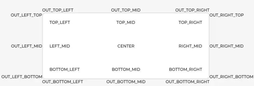
Changing font size in LVGL widgets
Code location:
examples\inc\lv_conf.h,lv_app_hwtest.cFunction: in practice, a screen may need multiple font sizes. You can enable multiple font sizes in
lv_conf.hand set the default font size. To set the font size, you need to style the widget so that it renders according to the set style. Using thelv_obj_add_stylefunction, different parts of the widget can be rendered in different states.#define LV_FONT_MONTSERRAT_16 1 // Enable 16pt font#define LV_FONT_MONTSERRAT_18 1 // Enable font 18#define LV_FONT_DEFAULT &lv_font_montserrat_18 // Set the default font size as 18static lv_style_t style_label;lv_style_init(&style_label); // Initialize stylelv_style_set_text_font(&style_label, &lv_font_montserrat_16); // Set font size to 16ptlv_obj_add_style(label,&style_label,0); // Set label theme styleLVGL widget event handling
Code location:
lv_app_hwtest.cFunction: in LVGL, you can add event callback functions to widgets so that when events such as clicking, scrolling, or redrawing occur, the event triggers and the callback function is executed. In the program, call the
lv_obj_add_event_cb(obj, event_cb, filter, user_data)function to add the event handlerevent_cbfor the eventfilterto the widgetobj. When the widgetobjtriggers thefilterevent, the system automatically calls theevent_cbfunction. The last parameter is a pointer to any custom data available in the event.//Add an event handler sw_event_cb for the LV_EVENT_VALUE_CHANGED event to the sw widgetlv_obj_add_event_cb(sw, sw_event_cb,LV_EVENT_VALUE_CHANGED,NULL);
Operation Result
Import and compile the 04_LVGL project using VS Code. After compilation, flash the .uf2 file from the
builddirectory, or directly flash 04_LVGL.uf2 file from thefirmware\Cdirectory for quick verification.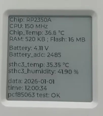
Working with Arduino
This chapter contains the following sections. Please read as needed:
Setting Up Development Environment
Please refer to the Install and Configure Arduino IDE Tutorial to download and install the Arduino IDE.
Example
The Arduino examples are located in the examples\Arduino directory of the example package.
| Example | Basic Program Description | Dependency Library |
|---|---|---|
| 01_GUI | GUI display program | - |
01_GUI
Example Description
- Uses SPI to communicate with the display, and implements functions such as displaying text and images via GUI.
Hardware Connection
- Connect the board to the computer using a USB cable
Code Analysis
Underlying Hardware Interface
We have encapsulated the hardware operations at a low level. Due to differences in hardware platforms, the internal implementations vary. If you need to understand the internal implementation, you can check the corresponding directory. Many definitions can be seen in DEV_Config.c(.h) under the directory: c\lib\Config.
Module initialization and exit handling
void DEV_Module_Init(void);void DEV_Module_Exit(void);TIPThis handles certain GPIO operations before using the display and after finishing.
GPIO read/write
void DEV_Digital_Write(uint_16 Pin, uint_8 Value);uint_8 DEV_Digital_Read(uint_16 Pin);SPI write data
void DEV_SPI_WriteByte(uint_8 Value);
Upper Layer Applications
For the screen, what if you need to paint, display Chinese and English characters, display pictures, etc., these are all done by the upper layer applications. Many users have asked about graphical processing. We provide some basic functionalities in the GUI, located in the directory: c\lib\GUI\GUI_Paint.c(.h)

The character fonts that the GUI depends on are located in the directory: c\lib\Fonts
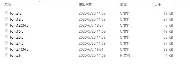
Create Image Attribute: Create a new image attribute, which includes the name, width, height, rotation angle, and color of the image cache.
void Paint_NewImage(uint16_t *image, uint16_t Width, uint16_t Height, uint16_t Rotate, uint16_t Color)Parameters:image: The name of the image cache, which is essentially a pointer to the starting address of the image cache;Width: The width of the image cache;Height: The height of image cache;Rotate: The rotation angle of the image;Color: The initial color of the image;Select Image Cache: Selects an image cache. The purpose of this selection is to allow you to create multiple image attributes. Since multiple image caches can exist, you can select each image you have created.
void Paint_SelectImage(uint8_t *image)Parameters:image: The name of the image cache, which is essentially a pointer to the starting address of the image cache;Image Rotation: Set the rotation angle for the selected image. It is best to use this after
Paint_SelectImage(). You can choose rotation angles of 0, 90, 180, or 270 degrees.void Paint_SetRotate(uint16_t Rotate)Parameters:Rotate: The image rotation angle. You can choose ROTATE_0, ROTATE_90, ROTATE_180, ROTATE_270 corresponding to 0, 90, 180, 270 degrees respectively.TIPThe starting pixel for coordinates differs under different rotation angles. Taking 1.14 as an example, the four images correspond to 0°, 90°, 180°, and 270° in order. This is for reference only.
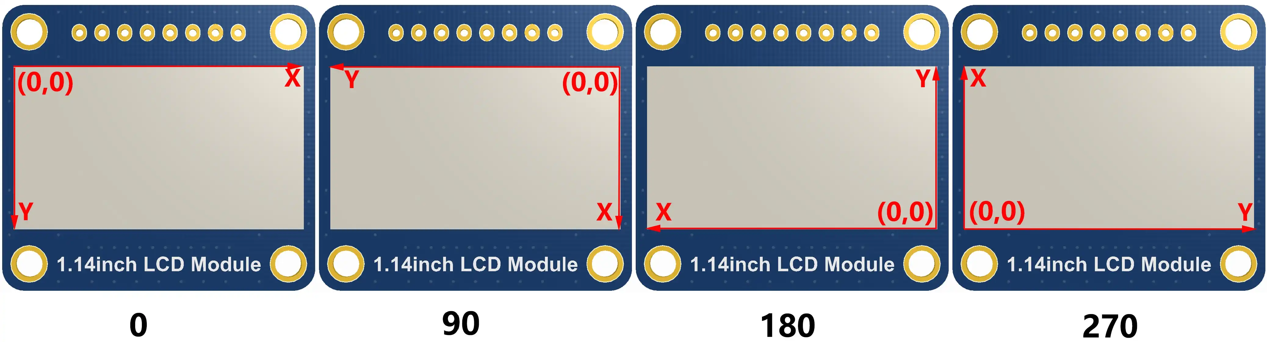
Image Mirroring: Set mirroring for the selected image. You can choose no mirroring, horizontal mirroring, vertical mirroring, or mirroring about the image center.
void Paint_SetMirroring(uint8_t mirror)Parameters:mirror: The mirroring method for the image. You can choose MIRROR_NONE, MIRROR_HORIZONTAL, MIRROR_VERTICAL, MIRROR_ORIGIN corresponding to no mirroring, horizontal mirroring, vertical mirroring, and mirroring about the image center respectively.Set Pixel Display Position and Color in Cache: This is one of the core GUI functions, handling the display position and color of a pixel within the cache.
void Paint_SetPixel(uint16_t Xpoint, uint16_t Ypoint, uint16_t Color)Parameters:Xpoint: The X-coordinate of the point within the image cache;Ypoint: The Y-coordinate of the point within the image cache;Color: The display color of the point;Fill Image Cache with Color: Fills the image cache with a specific color, typically used to clear the screen to white.
void Paint_Clear(uint16_t Color)Parameters:Color: The filled colorFill Partial Window in Image Cache with Color: Fill a specific window area within the image cache with a color, often used to clear a window to white, such as when updating time displays to clear the previous second.
void Paint_ClearWindows(uint16_t Xstart, uint16_t Ystart, uint16_t Xend, uint16_t Yend, uint16_t Color)Parameters:Xstart: The X starting coordinate of the window;Ystart: The Y starting coordinate of the window;Xend: The X ending coordinate of the window;Yend: The Y ending coordinate of the window;Color: The filled colorDraw Dot: Draw a dot at (Xpoint, Ypoint) in the image cache. You can choose the color, the size, and the style of the dot.
void Paint_DrawPoint(uint16_t Xpoint, uint16_t Ypoint, uint16_t Color, DOT_PIXEL Dot_Pixel, DOT_STYLE Dot_Style)Parameters:Xpoint: The X-coordinate of the dot;Ypoint: The Y-coordinate of the dot;Color: The filled colorDot_Pixel: The size of the dot, with 8 default sizes provided:typedef enum {DOT_PIXEL_1X1 = 1, // 1 x 1DOT_PIXEL_2X2 , // 2 X 2DOT_PIXEL_3X3 , // 3 X 3DOT_PIXEL_4X4 , // 4 X 4DOT_PIXEL_5X5 , // 5 X 5DOT_PIXEL_6X6 , // 6 X 6DOT_PIXEL_7X7 , // 7 X 7DOT_PIXEL_8X8 , // 8 X 8} DOT_PIXEL;Dot_Style: The style of the dot, defining the method to expand the size of the dot is that, whether to expand from the dot as the center or from the dot as the lower left corner to the upper right.typedef enum {DOT_FILL_AROUND = 1,DOT_FILL_RIGHTUP,} DOT_STYLE;Draw Line: Draw a line from (Xstart, Ystart) to (Xend, Yend) in the image cache. You can select the color, line width, and line style.
void Paint_DrawLine(uint16_t Xstart, uint16_t Ystart, uint16_t Xend, uint16_t Yend, uint16_t Color, LINE_STYLE Line_Style , LINE_STYLE Line_Style)Parameters:Xstart: The X starting coordinate of the line;Ystart: The Y starting coordinate of the line;Xend: The X ending coordinate of the line;Yend: The Y ending coordinate of the line;Color: The filled colorLine_width: The width of the line, with 8 default widths provided:typedef enum {DOT_PIXEL_1X1 = 1, // 1 x 1DOT_PIXEL_2X2 , // 2 X 2DOT_PIXEL_3X3 , // 3 X 3DOT_PIXEL_4X4 , // 4 X 4DOT_PIXEL_5X5 , // 5 X 5DOT_PIXEL_6X6 , // 6 X 6DOT_PIXEL_7X7 , // 7 X 7DOT_PIXEL_8X8 , // 8 X 8} DOT_PIXEL;Line_Style: The line style, choosing between solid line connection or dotted line connectiontypedef enum {LINE_STYLE_SOLID = 0,LINE_STYLE_DOTTED,} LINE_STYLE;Draw Rectangle: Draw a rectangle from (Xstart, Ystart) to (Xend, Yend) in the image cache. You can select the color, line width, and whether to fill the interior of the rectangle.
void Paint_DrawRectangle(uint16_t Xstart, uint16_t Ystart, uint16_t Xend, uint16_t Yend, uint16_t Color, DOT_PIXEL Line_width, DRAW_FILL Draw_Fill)Parameters:Xstart: The X starting coordinate of the rectangle;Ystart: The Y starting coordinate of the rectangle;Xend: The X ending coordinate of the rectangle;Yend: The Y ending coordinate of the rectangle;Color: The filled colorLine_width: The width of the rectangle's four sides, with 8 default widths provided:typedef enum {DOT_PIXEL_1X1 = 1, // 1 x 1DOT_PIXEL_2X2 , // 2 X 2DOT_PIXEL_3X3 , // 3 X 3DOT_PIXEL_4X4 , // 4 X 4DOT_PIXEL_5X5 , // 5 X 5DOT_PIXEL_6X6 , // 6 X 6DOT_PIXEL_7X7 , // 7 X 7DOT_PIXEL_8X8 , // 8 X 8} DOT_PIXEL;Draw_Fill: Fill option, determining whether to fill the interior of the rectangle:typedef enum {DRAW_FILL_EMPTY = 0,DRAW_FILL_FULL,} DRAW_FILL;Draw Circle: Draw a circle with center at (X_Center, Y_Center) and a radius of Radius in the image cache, and you can choose the color. You can select the color, line width, and whether to fill the interior of the circle.
void Paint_DrawCircle(uint16_t X_Center, uint16_t Y_Center, uint16_t Radius, uint16_t Color, DOT_PIXEL Line_width, DRAW_FILL Draw_Fill)Parameters:X_Center: The X-coordinate of the circle's center;Y_Center: The Y-coordinate of the circle's center;Radius: The radius of the circle;Color: The filled colorLine_width: The width of the circle's arc, with 8 default widths provided:typedef enum {DOT_PIXEL_1X1 = 1, // 1 x 1DOT_PIXEL_2X2 , // 2 X 2DOT_PIXEL_3X3 , // 3 X 3DOT_PIXEL_4X4 , // 4 X 4DOT_PIXEL_5X5 , // 5 X 5DOT_PIXEL_6X6 , // 6 X 6DOT_PIXEL_7X7 , // 7 X 7DOT_PIXEL_8X8 , // 8 X 8} DOT_PIXEL;Draw_Fill: Fill option, determining whether to fill the interior of the circle:typedef enum {DRAW_FILL_EMPTY = 0,DRAW_FILL_FULL,} DRAW_FILL;Draw Ascii Character: Draw an Ascii character in the image cache with (Xstart, Ystart) as the top-left vertex. You can select the Ascii visible character font, foreground color, and background color.
void Paint_DrawChar(uint16_t Xstart, uint16_t Ystart, const uint8_t Ascii_Char, sFONT* Font, uint16_t Color_Foreground, uint16_t Color_Background)Parameters:Xstart: The X-coordinate of the number's top-left vertex;Ystart: The Y-coordinate of the number's top-left vertex;Ascii_Char: The Ascii character;Font: The Ascii visible character font. The following fonts are provided in the Fonts folder:font8: 5*8 fontfont12: 7*12 fontfont16: 11*16 fontfont20: 14*20 fontfont24: 17*24 fontColor_Foreground: The font color;Color_Background: The background color;Draw English String: Draw a string of English characters in the image cache with (Xstart, Ystart) as the top-left vertex. You can select the Ascii visible character font, foreground color, and background color.
void Paint_DrawString_EN(uint16_t Xstart, uint16_t Ystart, const uint8_t * pString, sFONT* Font, uint16_t Color_Foreground, uint16_t Color_Background)Parameters:Xstart: The X-coordinate of the number's top-left vertex;Ystart: The Y-coordinate of the number's top-left vertex;pString: The string, which is a pointer;Font: The Ascii visible character font. The following fonts are provided in the Fonts folder:font8: 5*8 fontfont12: 7*12 fontfont16: 11*16 fontfont20: 14*20 fontfont24: 17*24 fontColor_Foreground: The font color;Color_Background: The background color;Draw Chinese String: Draw a string of Chinese characters in the image cache with (Xstart, Ystart) as the top-left vertex. You can select the GB2312 encoded character font, foreground color, and background color.
void Paint_DrawString_CN(uint16_t Xstart, uint16_t Ystart, const uint8_t * pString, cFONT* font, uint16_t Color_Foreground, uint16_t Color_Background)Parameters:Xstart: The X-coordinate of the number's top-left vertex;Ystart: The Y-coordinate of the number's top-left vertex;pString: The string, which is a pointer;Font: The GB2312 encoded character font. The following fonts are provided in the Fonts folder:font12CN: Ascii character 11*21 font, Chinese 16*21 fontfont24CN: Ascii character 24*41 font, Chinese 32*41 fontColor_Foreground: The font color;Color_Background: The background color;Draw Number: Draw a number string in the image cache with (Xstart, Ystart) as the top-left vertex. You can select the Ascii visible character font, foreground color, background color, and decimal places.
void Paint_DrawNum(uint16_t Xpoint, uint16_t Ypoint, uint32_t Nummber, sFONT* Font, uint16_t Digit,uint16_t Color_Foreground, uint16_t Color_Background);Parameters:Xstart: The X-coordinate of the number's top-left vertex;Ystart: The Y-coordinate of the number's top-left vertex;Number: The displayed number, here is stored in a 32-bit long int type, which can be displayed up to 2147483647.Font: The Ascii visible character font. The following fonts are provided in the Fonts folder:font8: 5*8 fontfont12: 7*12 fontfont16: 11*16 fontfont20: 14*20 fontfont24: 17*24 fontDigit: The number of decimal places to displayColor_Foreground: The font color;Color_Background: The background color;Display Time: Display a time period in the image cache with (Xstart, Ystart) as the top-left vertex. You can select the Ascii visible character font, foreground color, and background color.
void Paint_DrawTime(uint16_t Xstart, uint16_t Ystart, PAINT_TIME *pTime, sFONT* Font, uint16_t Color_Background, uint16_t Color_Foreground)Parameters:Xstart: The X-coordinate of the number's top-left vertex;Ystart: The Y-coordinate of the number's top-left vertex;pTime: The time to display, using a predefined time structure; simply pass the hour, minute, and second digits to the parameters;Font: The Ascii visible character font. The following fonts are provided in the Fonts folder:font8: 5*8 fontfont12: 7*12 fontfont16: 11*16 fontfont20: 14*20 fontfont24: 17*24 fontColor_Foreground: The font color;Color_Background: The background color;
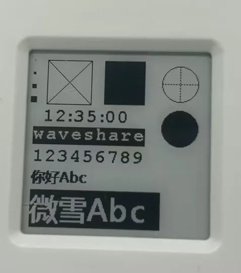
Operation Result
Resources
1. Hardware Resources
Development Board Design Files
2. Technical Manuals
Datasheets
3. Official Resources
- Raspberry Pi Official Documentation
- Raspberry Pi-Open Source Examples
4. Development Software
- pico-vscode package
- Chinese character conversion software
- Font Library Conversion Tutorial
- Image bitmap conversion software
- Image Bitmap Conversion Tutorial
5. Example
Support
Monday-Friday (9:30-6:30) Saturday (9:30-5:30)
Email: services01@spotpear.com
[Tutorial Navigation]
- Features
- Onboard Resources
- Interface Introduction
- Dimensions
- Working with MicroPython
- Working with C/C++
- Working with Arduino
- Resources
- 1. Hardware Resources
- 2. Technical Manuals
- 3. Official Resources
- 4. Development Software
- 5. Example
- Support