


- sales/support
Google Chat:---
- sales
+86-0755-88291180
- sales01
sales@spotpear.com
- sales02
dragon_manager@163.com
- support
tech-support@spotpear.com
- CEO-Complaints
zhoujie@spotpear.com
- Only Tech-Support
WhatsApp:13246739196
- Purchase/Shipping/Refund
WhatsApp:13424403025
- HOME
- >
- ARTICLES
- >
- Common Moudle
- >
- ESP
ESP32-S3-SIM7670G-4G User Guide
Overview
The ESP32-S3-SIM7670G-4G (hereinafter referred to as the development board) is a multifunctional, high-performance microcontroller development board designed by Waveshare. It integrates an SIM7670G 4G communication module, a universal OV camera interface, a TF card slot, RGB colorful LED, an 18650 battery holder (18650 battery is NOT included), a battery voltage measurement IC, a solar panel charging interface, and other peripherals. It employs the ESP32-S3R2, a System On Chip (SoC) that integrates low-power Wi-Fi and BLE5.0. Additionally, it comes with an external 16MB Flash and 2MB PSRAM. The SoC incorporates a hardware encryption accelerator, random number generator (RNG), HMAC, and digital signature modules, meeting the security requirements of the Internet of Things (IoT).
The A7670E 4G communication module provides mobile network capabilities, enabling functionalities like portable Wi-Fi and IoT data transmission when combined with the ESP32-S3R2. Its various low-power operating modes cater to power consumption demands in IoT, mobile devices, outdoor monitoring, smart home applications, and other scenarios.
Features
- Comes with a high-performance Xtensa® 32-bit LX7 dual-core processor with up to 240MHz.
- Support 2.4GHz WiFi (802.11 b/g/n) and Bluetooth® 5 (LE) with onboard antenna.
- Built-in 512KB of SRAM and 384KB ROM, with onboard 2MB PSRAM and an external 16MB Flash memory.
Hardware Description
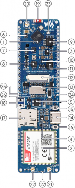
- Onboard patch antenna, you can use it or short it to connect the external antenna as shown in ⑲ and ⑳.
- Onboard RGB colorful beads, WS2812B driver as shown in ㉓.
- Onboard Camera interface: using 24pin camera interface as shown in ⑫.
The supported camera list is shown below:
| model | max resolution | color type | Len Size |
|---|---|---|---|
| OV2640 | 1600 x 1200 | color | 1/4" |
| OV3660 | 2048 x 1536 | color | 1/5" |
| OV5640 | 2592 x 1944 | color | 1/4" |
| OV7670 | 640 x 480 | color | 1/6" |
| OV7725 | 640 x 480 | color | 1/4" |
| NT99141 | 1280 x 720 | color | 1/4" |
| GC032A | 640 x 480 | color | 1/10" |
| GC0308 | 640 x 480 | color | 1/6.5" |
| GC2145 | 1600 x 1200 | color | 1/5" |
| BF3005 | 640 x 480 | color | 1/4" |
| BF20A6 | 640 x 480 | color | 1/10" |
| SC101IOT | 1280 x 720 | color | 1/4.2" |
| SC030IOT | 640 x 480 | color | 1/6.5" |
| SC031GS | 640 x 480 | color | 1/6" |
- Onboard TF-Card slot, support storing files and pictures as shown in ⑬.
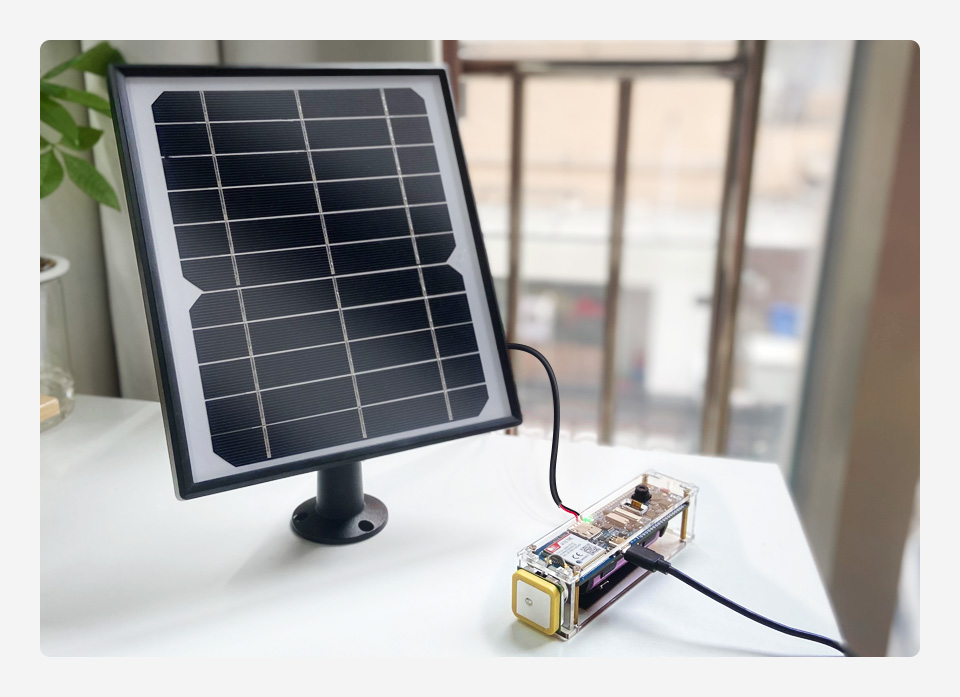
- Onboard solar panel charging interface as shown in ⑱.
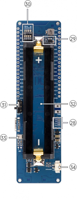
- You can select different resistor values on the back to switch the solar input voltage.
- When the solar panel is charging, the onboard green LED will light up, as shown in figures ㉖ and ㉘.
- The onboard circuit switch allows you to control the circuit on/off when using the 18650 power supply, as shown in figure ㉛.
- Onboard USB to UART chip and automatic download circuit, after connecting the Type-C cable to program the demo and firmware, as shown in ⑦.
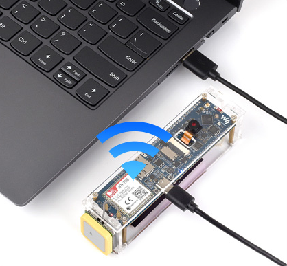
- Using ESP32-S3 USB to connect to the A/SIM7670X USB connector, and using TinyUSB protocol to realize ppp dial-up network access as the portable WIFI.
- The onboard 18650 battery interface is designed for a single 3.7V 18650 lithium battery. Pay attention to the polarity markings on the lithium battery interface.
- When the battery is reversed, the onboard yellow LED will light up as a warning, as shown in ㉕.
- The development board reserves GPIO pins for external device connections, which can be flexibly configured as I2C, SPI, and other peripheral functions. For detailed functions, please refer to the GPIO allocation description.
- Onboard a GNSS IPEX1 interface. After powering on, you can enable the GNSS positioning function using the relevant commands, as shown in ㉑.
- Furthermore, there is a DIP switch onboard for convenient control of the Camera, USB HUB circuit, and 4G module power supply. It can also control the USB circuit switching of the 4G module, as depicted in figure ㉚.
- Onboard LED Description:
- Onboard battery anti-reverse warning LED, the yellow LED is on when the batteries are reversely connected as shown in ㉕.
- Onboard green solar panel charging LED, the LED is on when the solar panel input voltage is active, as shown in ㉖.
- Onboard blue power indicator, lights on when the power is connected to start up, as shown in ㉔.
- The onboard module network indicator will turn on in red once the module is powered on. After successfully registering to the network, it will flash at a frequency of 200ms, as shown in figure ㉗.
Hardware Connection
This development board's ESP32-S3 UART to USB module and 4G module USB use the same Type-C interface, and you can choose the connection between the USB interface of the 4G module and the ESP32-S3 USB connector or the Type-C interface through the USB channel of the dip switch on the back of the development board. This function is mainly used when the ESP32-S3 uses Tiny USB 4G module communication as a portable WiFi, wireless hotspot.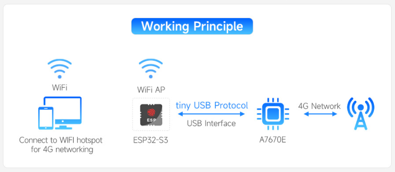
Solar Panel Charging
The solar input selection resistor on the back of the development board can switch the maximum voltage of solar input. By default, the 0-ohm resistor is used to connect to the 5V marking position, supporting solar panels with 5~6V voltage input. When using solar panels with higher voltage input, the corresponding voltage solder joints should be shorted.
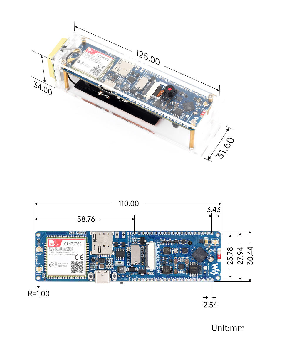
Dimensions
Working with ESP-IDF
This chapter introduces the setup of the ESP-IDF environment, including the installation of Visual Studio, the Espressif IDF plugin, program compilation and download, as well as testing of sample programs. It aims to help users gain proficiency with the development board for secondary development.
Environment Setup
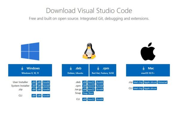
Download and Install VSCode
- Open the download page of the official VSCode website, and select the corresponding system and system bit to download.
- After running the installation package, the rest can be installed by default, but here for the subsequent experience, it is recommended to check boxes 1, 2, and 3
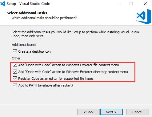
- After the first and second items are enabled, you can open VSCode directly by right-clicking files or directories, which can improve the subsequent user experience.
- After the third item is enabled, you can select VSCode directly when you choose how to open it.
Installing the Espressif IDF Plugin
- The "online installation" is generally recommended for installing the Espressif IDF plugin. If online installation is not possible due to network issues, then "offline installation" can be used.
- For the tutorial on installing the Espressif IDF plugin, please refer to: Install Espressif IDF Plugin Tutorial
Run the First ESP-IDF Demo
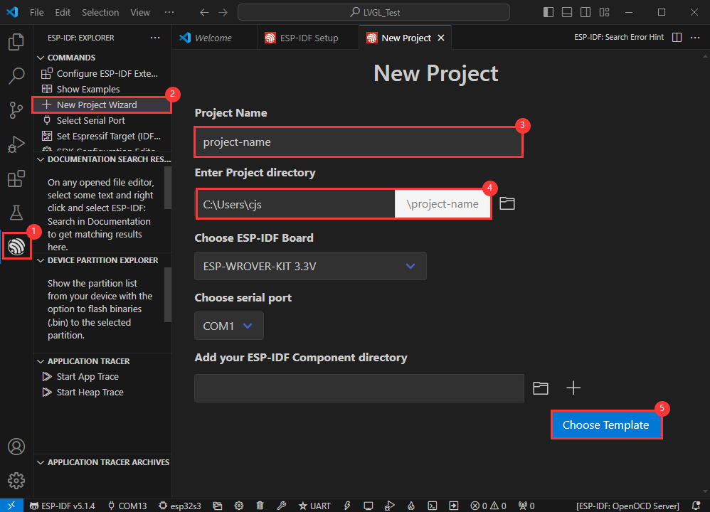
New Project
Create Demo
- Using the shortcut F1, enter esp-idf:show examples projects
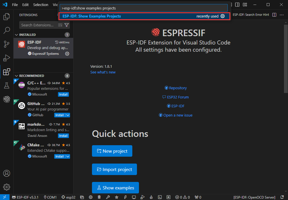
- Select your current IDF version
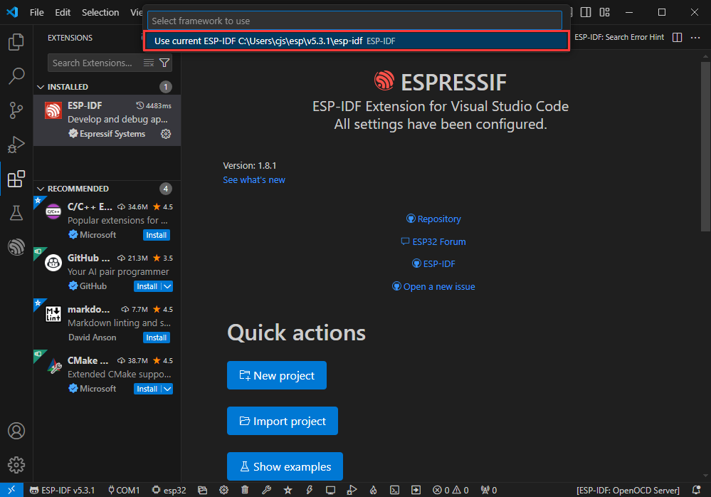
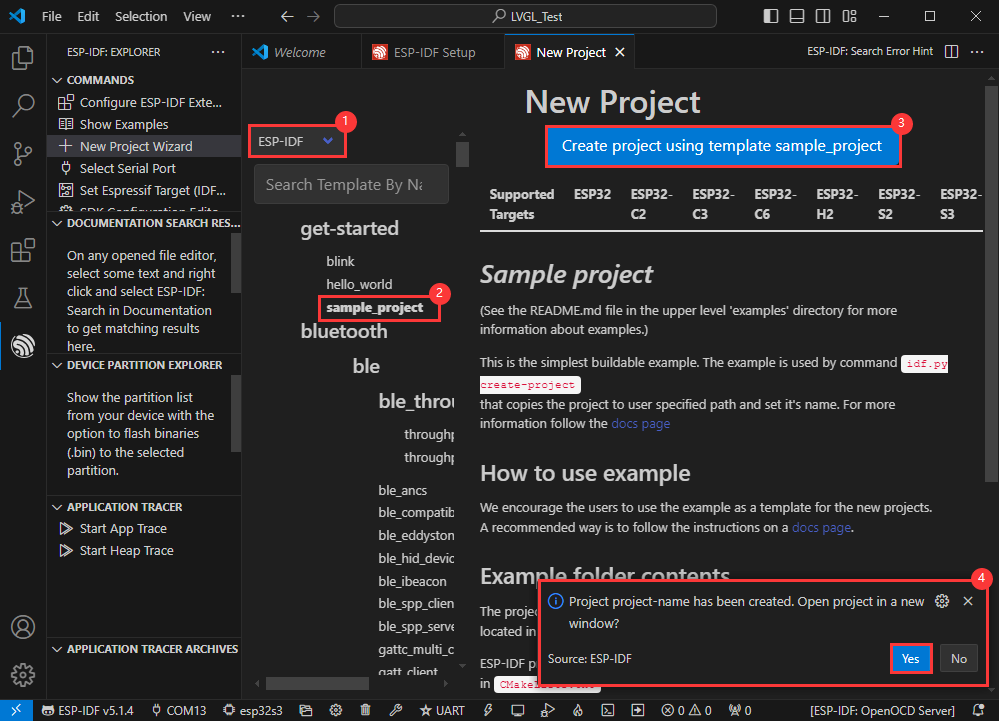
- Take the Hello world demo as an example
①Select the corresponding demo
②Its readme will state what chip the demo applies to (how to use the demo and the file structure are described below, omitted here)
③Click to create the demo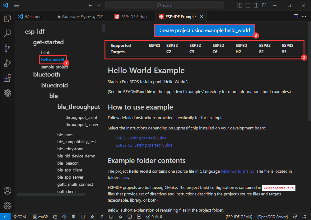
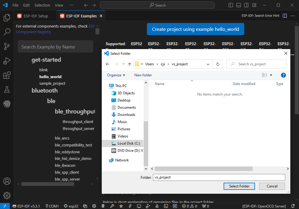
- Select the path to save the demo, and require that the demos cannot use folders with the same name
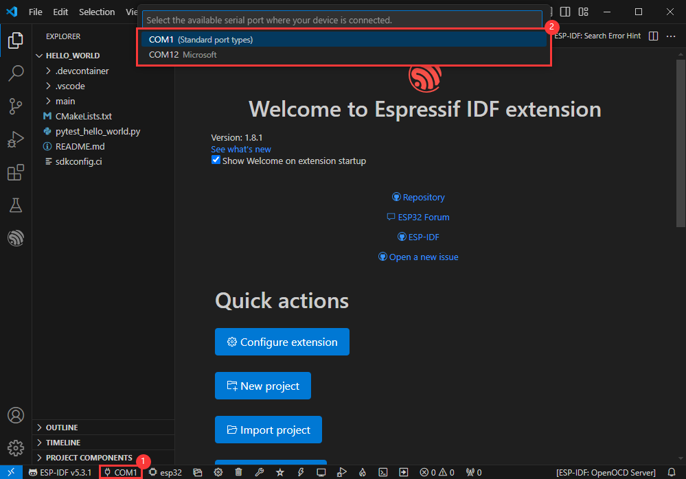
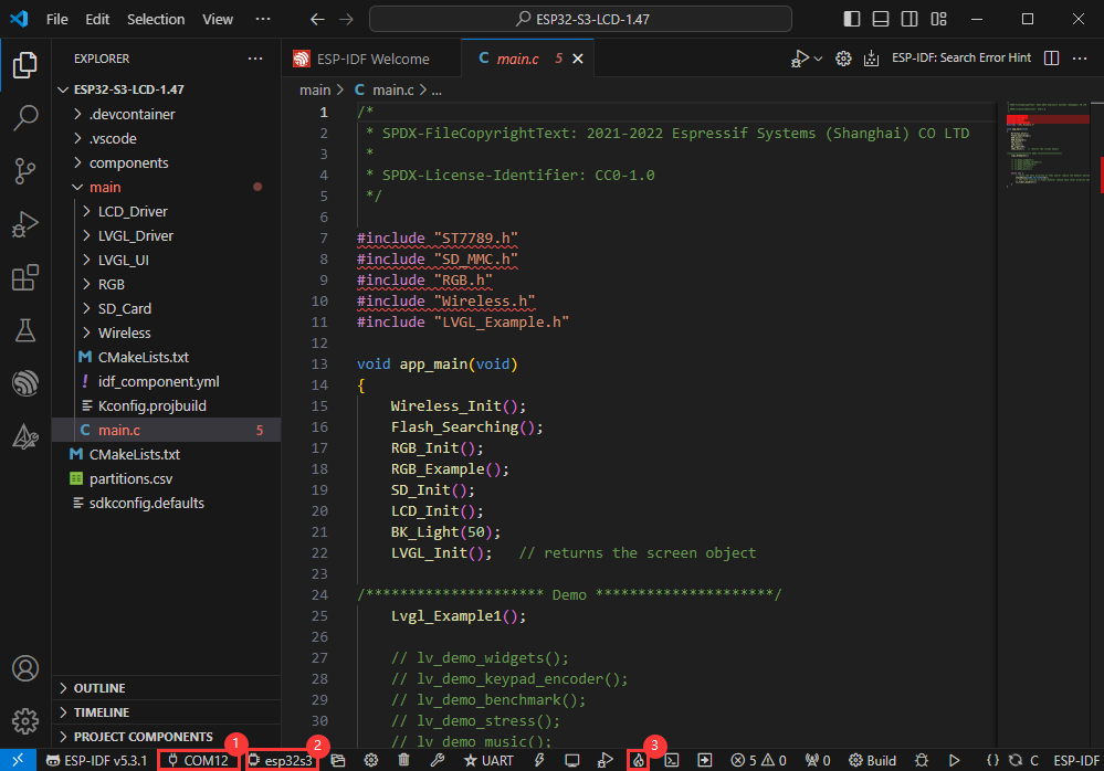
Modify COM port
- The corresponding COM ports are shown here, click to modify them
- Please select the COM ports according to your device (You can view it from the device manager)
- In case of a download failure, please press the Reset button for more than 1 second or enter download mode, and wait for the PC to recognize the device again before downloading once more
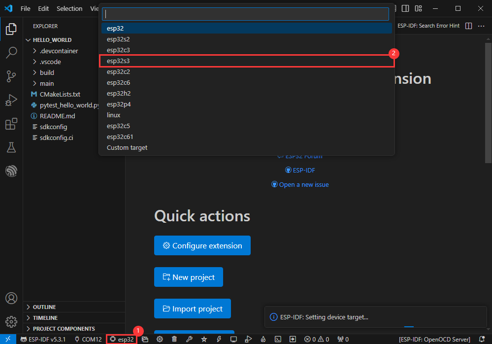
Modify driver object
- Select the object we need to drive, which is our main chip ESP32S3
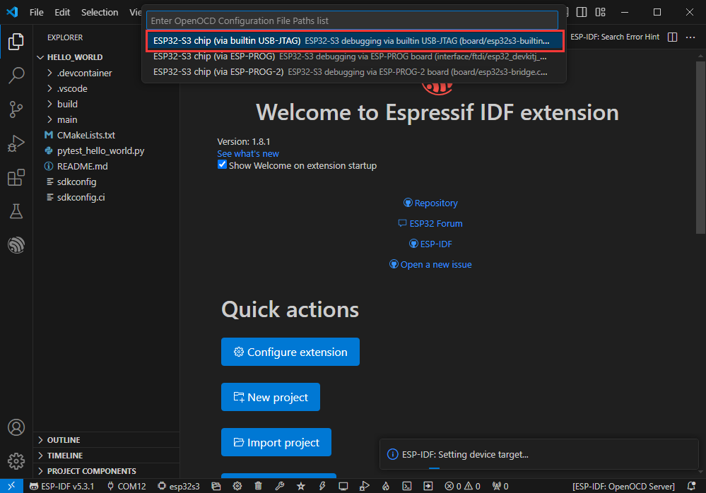
- Choose the path to openocd, it doesn't affect us here, so let's just choose one
Introduction to other status bar functions
①.ESP-IDF Development Environment Version Manager, when our project requires differentiation of development environment versions, it can be managed by installing different versions of ESP-IDF. When the project uses a specific version, it can be switched to by utilizing it
②.Device flashing COM port, select to flash the compiled program into the chip
③.Select set-target chip model, select the corresponding chip model, for example, ESP32-P4-NANO needs to choose esp32p4 as the target chip
④.menuconfig, click it to Modify sdkconfig configuration file Project configuration details
⑤.fullclean button, when the project compilation error or other operations pollute the compiled content, you can clean up all the compiled content by clicking it
⑥.Build project, when a project satisfies the build, click this button to compile
⑦.Current download mode, the default is UART
⑧.flash button, when a project build is completed, select the COM port of the corresponding development board, and click this button to flash the compiled firmware to the chip
⑨.monitor enable flashing port monitoring, when a project passes through Build --> Flash, click this button to view the log of output from flashing port and debugging port, so as to observe whether the application works normally
⑩.Debug
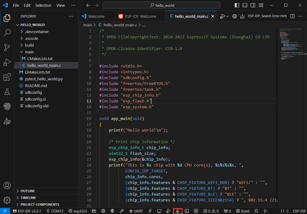
⑪.Build Flash Monitor one-click button, which is used to continuously execute Build --> Flash --> Monitor, often referred to as “little flame”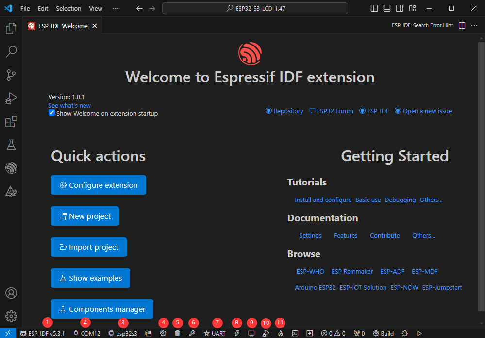
Compile, flash and serial port monitor
- Click on the all-in-one button we described before to compile, flash and open the serial port monitor.
- It may take a long time to compile especially for the first time
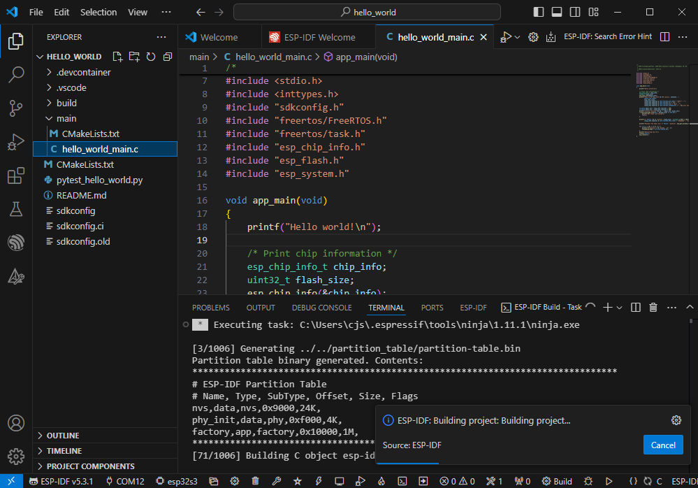
- During this process, the ESP-IDF may take up a lot of CPU resources, so it may cause the system to lag
- If it is the first time to flash the program for a new project, you will need to select the download method, and select UART
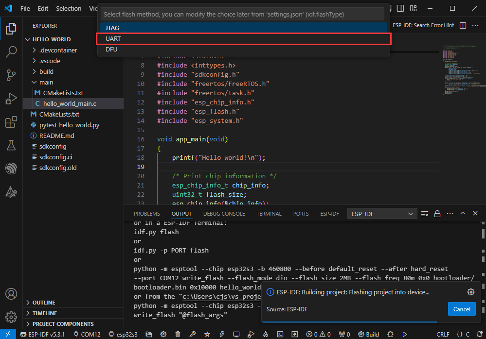
- This can also be changed later in the Download methods section (click on it to pop up the options)
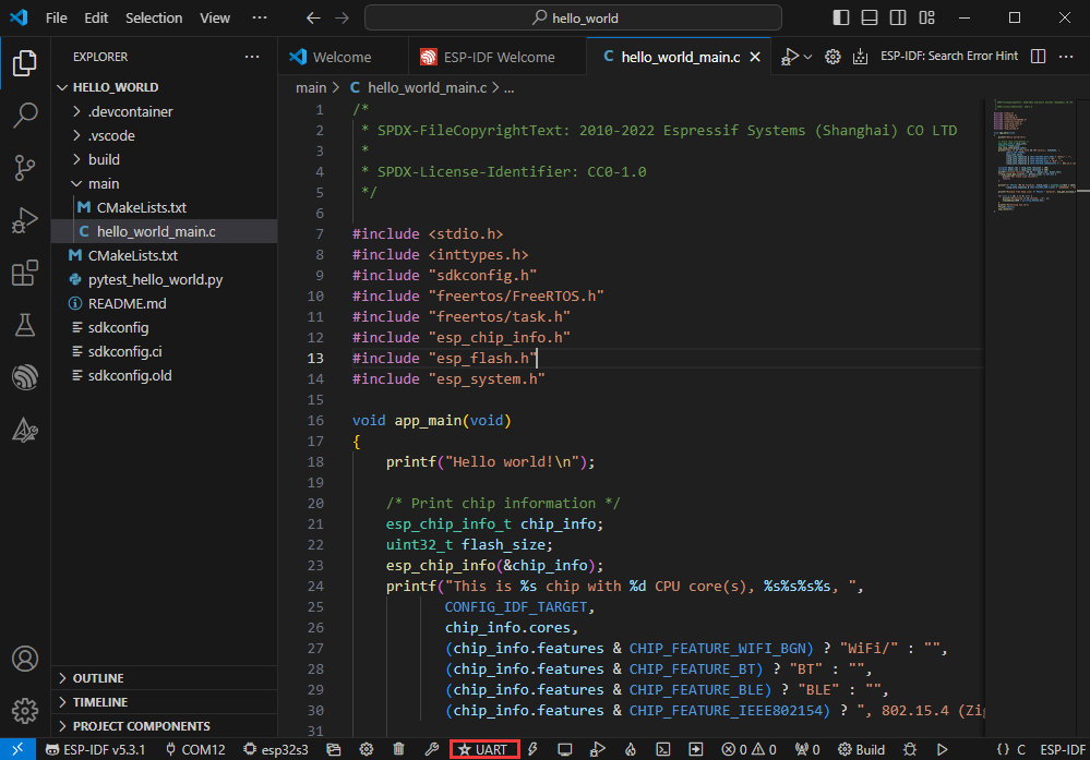
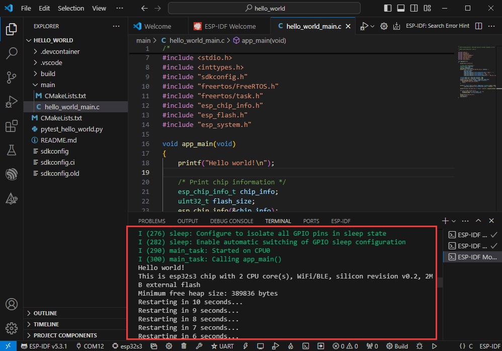
- As it comes with the onboard automatic download circuit, it can be downloaded automatically without manual operation
- After successful download, it will automatically enter the serial monitor, you can see the chip output the corresponding information and be prompted to restart after 10S
Use the IDF demos
Open in the software
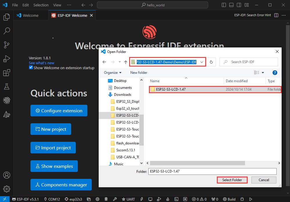
- Open VScode software and select the folder to open the demo
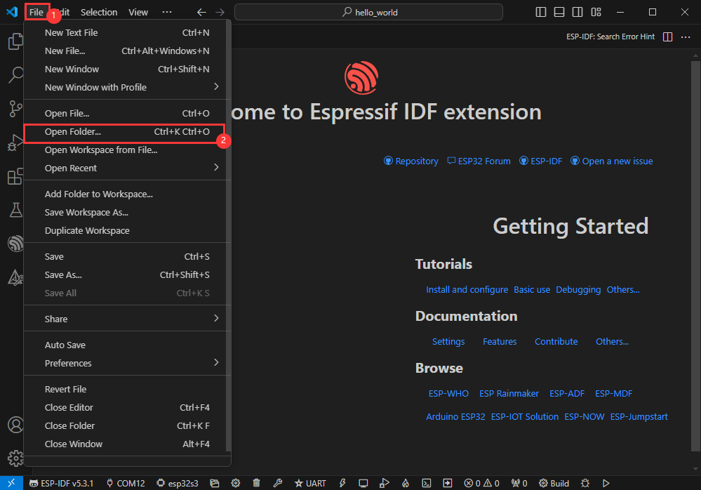
- Select the provided ESP-IDF example and click to select the file (located in the Examples/Demo/ESP-IDF path)
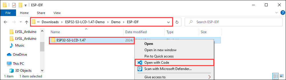
Open from outside the software
- Select the project directory correctly and open the project, otherwise it will affect the compilation and flashing of subsequent programs
- After connecting the device, select the COM port and model, click below to compile and flash to achieve program control
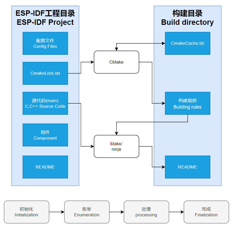
ESP-IDF Project Details
- Component: The components in ESP-IDF are the basic modules for building applications, each component is usually a relatively independent code base or library, which can implement specific functions or services, and can be reused by applications or other components, similar to the definition of libraries in Python development.
- Component reference: The import of libraries in the Python development environment only requires to "import library name or path", while ESP-IDF is based on the C language, and the importing of libraries is configured and defined through
CMakeLists.txt. - The purpose of CmakeLists.txt: When compiling ESP-IDF, the build tool
CMakefirst reads the content of the top-levelCMakeLists.txtin the project directory to read the build rules and identify the content to be compiled. When the required components and demos are imported into theCMakeLists.txt, the compilation toolCMakewill import each content that needs to be compiled according to the index. The compilation process is as follows:
- Component reference: The import of libraries in the Python development environment only requires to "import library name or path", while ESP-IDF is based on the C language, and the importing of libraries is configured and defined through
Demo
| Demo | Basic Description |
|---|---|
| Wireless_USB_flash_drive | The ESP32-S3-GEEK can be used as a USB disk with wireless access capabilities |
Wireless_USB_flash_drive
Program Description
- This routine allows the ESP32-S3-GEEK to be used as a USB disk with wireless access capabilities. When combined with SD card storage, it can become a high-capacity wireless storage device. Additionally, you can connect to the ESP32-S3-GEEK's hotspot to upload and download via an HTTP file server, greatly facilitating user operations. It is suitable for learning the USB MSC functionality of the ESP32, as it can act as a storage device connected to a USB host, supporting various storage methods, with callback functions to handle various events, and testing for stability and reliability
- To exit the program, simply press the boot button and power cycle the device
Hardware connection
- Insert the TF card into the development board
- Connect the development board to the computer
Code analysis
- init_fat():Initializes the FAT file system. Depending on the configuration, it mounts either the internal flash memory or an external TF card
- If using internal flash memory, a specific function is selected for mounting based on the ESP-IDF version
- If using an external TF card, it is initialized and mounted according to the interface type (SPI or SDIO)
- app_main ():The main function that coordinates the initialization of various parts of the program, including file storage, Wi-Fi (if configured), and USB MSC
- Calls
init_fatto initialize file storage - If Wi-Fi is configured, it initializes and starts the file server
- Initializes tinyUSB and installs the driver
- Calls
Code Burning
- Ensure the TF card is installed
- Select the model (esp32s3) and port
- Download via UART
- Burn the program
Result demonstration
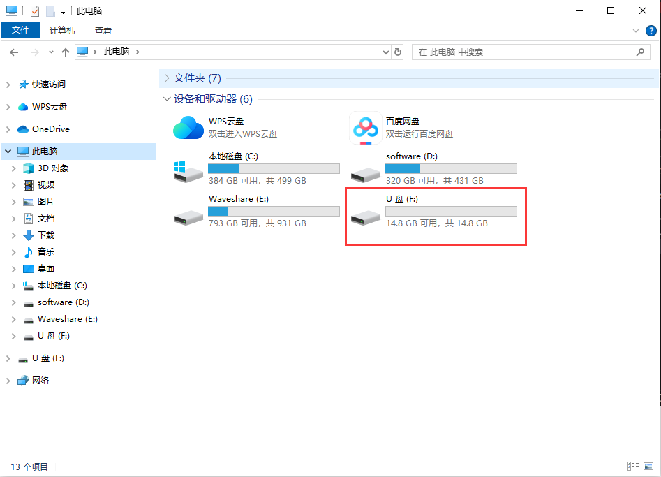
- After programming, unplug and plug the ESP32-S3-GEEK again, and you can see a new USB flash driver
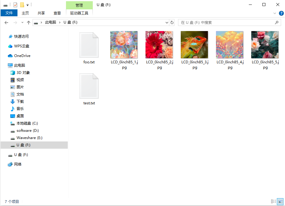
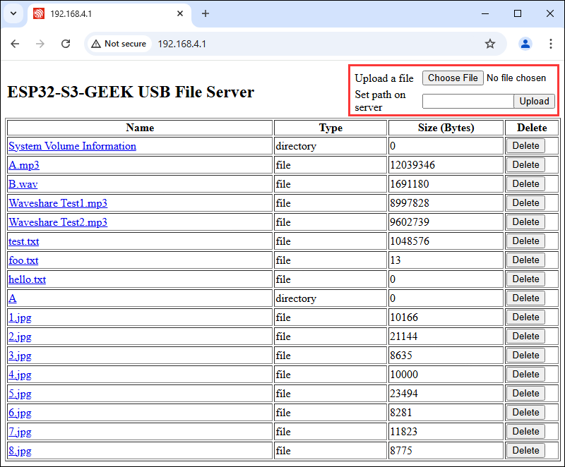
- You can open the USB drive to browse through the files on the TF card and perform various operations such as adding, deleting, modifying, and checking files
- Enter the PC's WIFI setting, connect to the ESP32-S3-GEEK's AP, and input the password of "Waveshare"
- After connecting successfully, open the browser, and log in to IP: 192.168.4.1
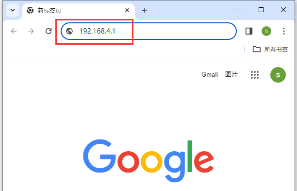
- After login successfully, you can upload and download files wirelessly
Cat-1 Module Command Set
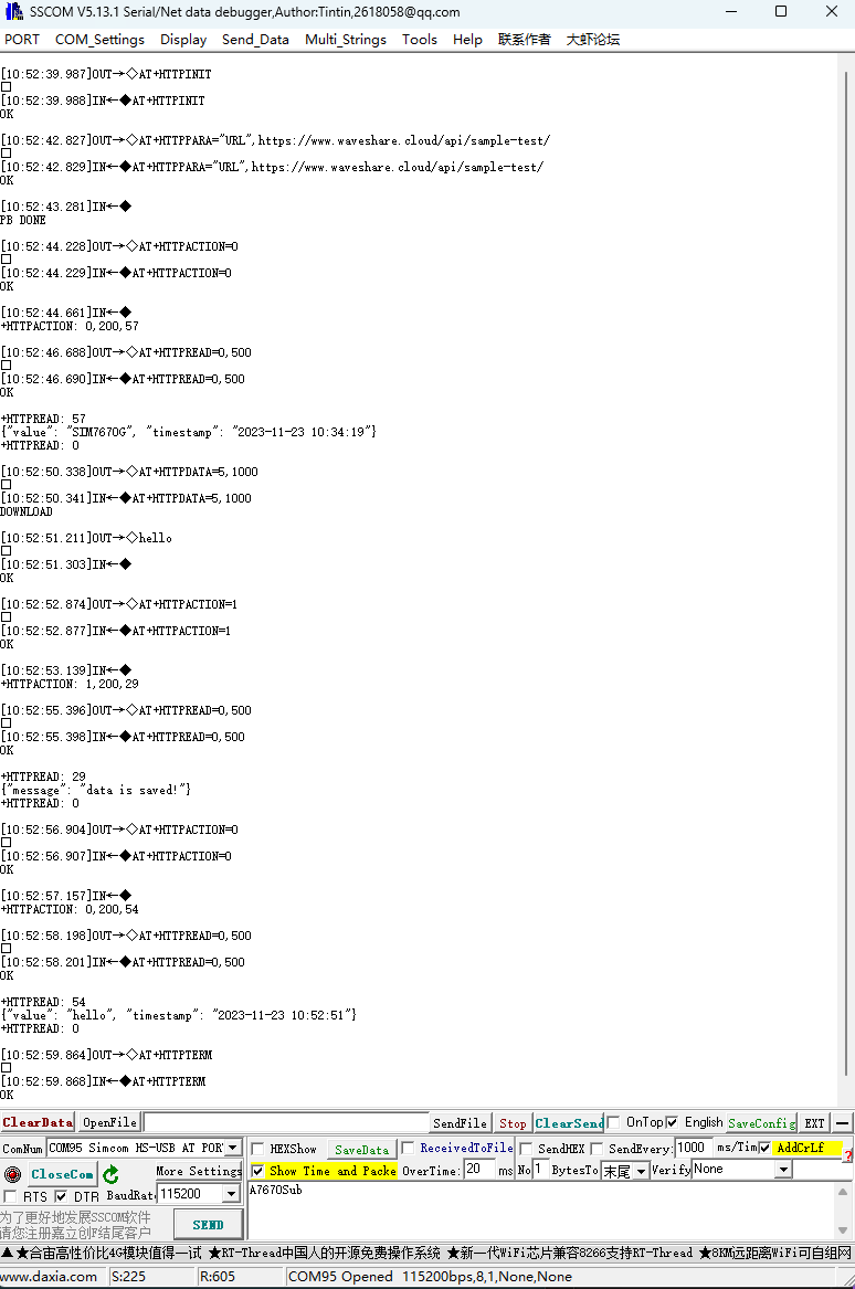
HTTP
AT Command | Command Description | Return |
AT+HTTPINIT | Open HTTP service | OK |
AT+HTTPPARA="URL",https://www.waveshare.cloud/api/sample-test/ | Connect to the remote server | OK |
AT+HTTPDATA=5,1000 | Input the data | DOWNLOAD <Enter hello OK |
AT+HTTPACTION=0 | Open HTTP request, 0:GET; 1:POST; 2:HEAD; 3:DELETE; 4:PUT | OK +HTTPACTION: 0,200,54 |
AT+HTTPTERM | Close HTTP service | OK |
AT+HTTPPARA | Set HTTP parameters | OK |
AT+HTTPHEAD | Read the HTTP response header message | OK |
AT+HTTPREAD | Read the HTTP response message | OK |
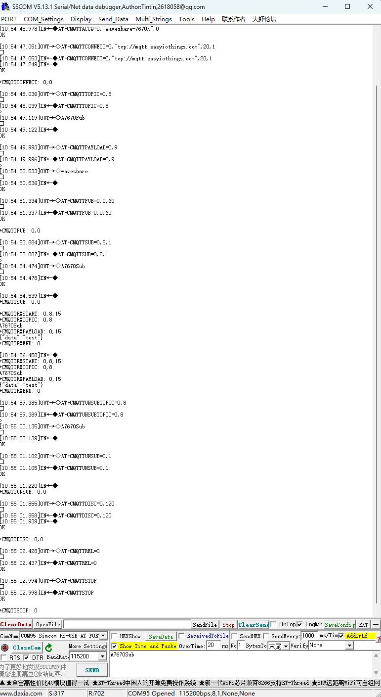
MQTT
AT Command | Command Description | Return |
AT+CMQTTSTART | Open MQTT service | OK |
AT+CMQTTACCQ=0,"Waveshare-7670X",0 | Apply for MQTT client | OK |
AT+CMQTTCONNECT=0,"tcp://mqtt.easyiothings.com",20,1 | Send MQTT request, connect to the private MQTT server (MQTTS) | OK |
AT+CMQTTTOPIC=0,8 | Input the message to publish the topic | >A7670Pub OK |
AT+CMQTTPAYLOAD=0,9 | Input the message to be published | OK >waveshare |
AT+CMQTTPUB=0,0,60 | Publish the message | OK +CMQTTPUB: 0,0 |
AT+CMQTTSUB=0,8,1 | Subscribe to message topic | >A7670Sub OK +CMQTTSUBTOPIC: 0,0 [10:03:39.665]Receive←◆ +CMQTTRXSTART: 0,8,15 +CMQTTRXTOPIC: 0,8 A7670Sub +CMQTTRXPAYLOAD: 0,15 {"data":"test"} +CMQTTRXEND: 0 |
AT+CMQTTSTOP | Stop MQTT service | OK |
AT+CMQTTREL | Release the client | OK |
AT+CMQTTUNSUBTOPIC | Unsubscribe the topic | OK |
AT+CMQTTUNSUB | Release subscription | OK |
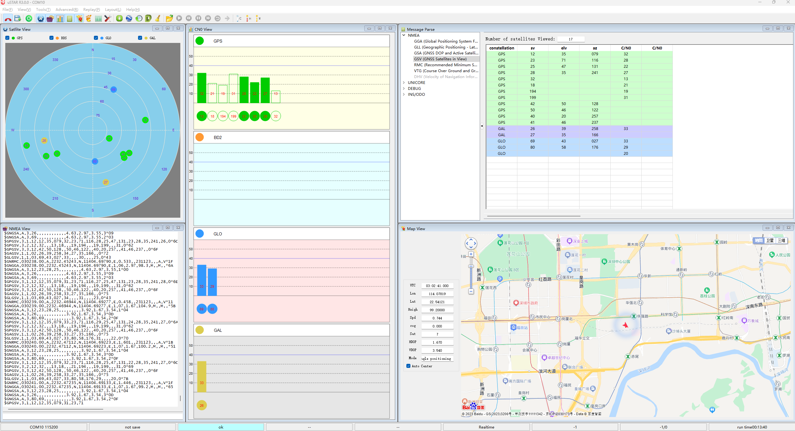
GNSS
| AT+CGNSSPWR=1 | Open GNSS | +CGNSSPWR: READY! |
| AT+CGNSSTST=1 | Open GNSS data output | OK |
Demo Explaination
ESP32-S3 Application
Camera
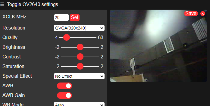
This demo is based on the CameraWebServer demo of the ESP32.
- Firstly, you need to set the WiFi name and password and switch the hardware to ESP32S3 by default.
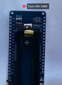
- Please turn on the CAM of the DIP switch on the back of the development board, and connect to the supported cameras.
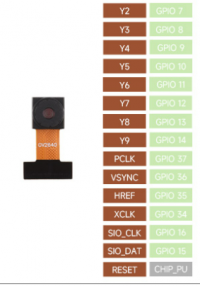
- Please check CameraPins.
#define PWDN_GPIO_NUM     -1
#define RESET_GPIO_NUM    -1
#define XCLK_GPIO_NUM     34
#define SIOD_GPIO_NUM     15
#define SIOC_GPIO_NUM     16
#define Y9_GPIO_NUM       14
#define Y8_GPIO_NUM       13
#define Y7_GPIO_NUM       12
#define Y6_GPIO_NUM       11
#define Y5_GPIO_NUM       10
#define Y4_GPIO_NUM       9
#define Y3_GPIO_NUM       8
#define Y2_GPIO_NUM       7
#define VSYNC_GPIO_NUM    36
#define HREF_GPIO_NUM     35
#define PCLK_GPIO_NUM     37
- Program the demo Burn the code and open the terminal to access the prompted IP.
TF-Card
- Insert the TF-Card into the TF card slot.
- Pinout definition:
const int SDMMC_CLK = 5;
const int SDMMC_CMD = 4;
const int SDMMC_DATA = 6;
const int SD_CD_PIN = 46;
- Program the demo, and open the terminal to display the file content:
RGB
Onboard a WS2812b RGB LED, and the signal pin is 38.
After programming the sample demo, the LED light is expected to display a gradient color.
BAT
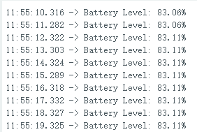
This development board utilizes the MAX17048 as the battery charge measurement IC.
- First, confirm the I2C pin.
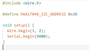
- Program the code and change the threshold.
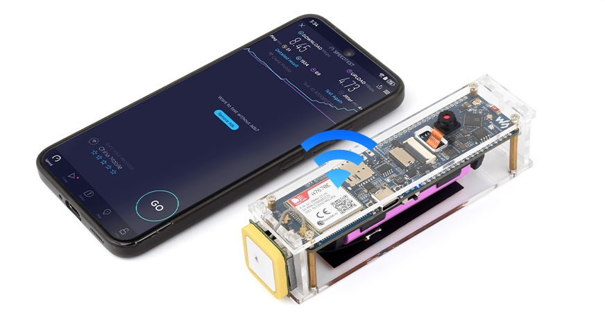
Portable WIFI Demo
- This demo uses the TinyUSB protocol stack to communicate with a 4G Cat-1 module, using ppp dial-up to provide the network to the ESP32-S3.
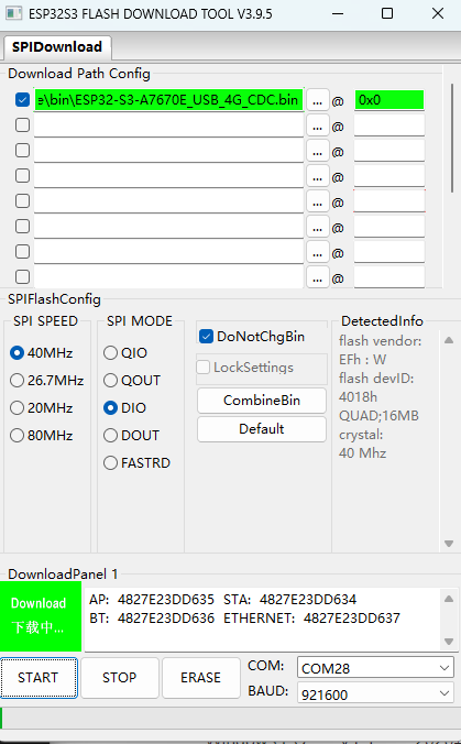
- This demo uses the compiled firmware, please download Flash Tools first.
- Download the firmware:
- Open the Flash Tools, select the development mode, choose the firmware, with the address set to "0x0", as shown in the diagram, and insert the SIM card to download and start the program.
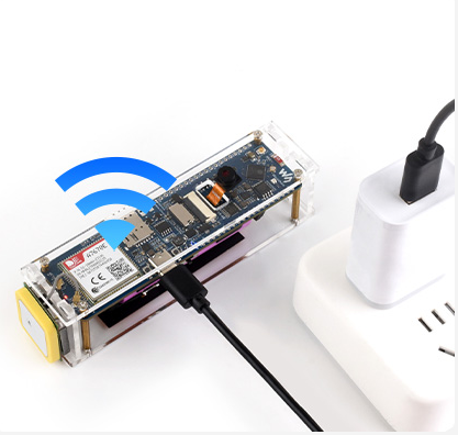
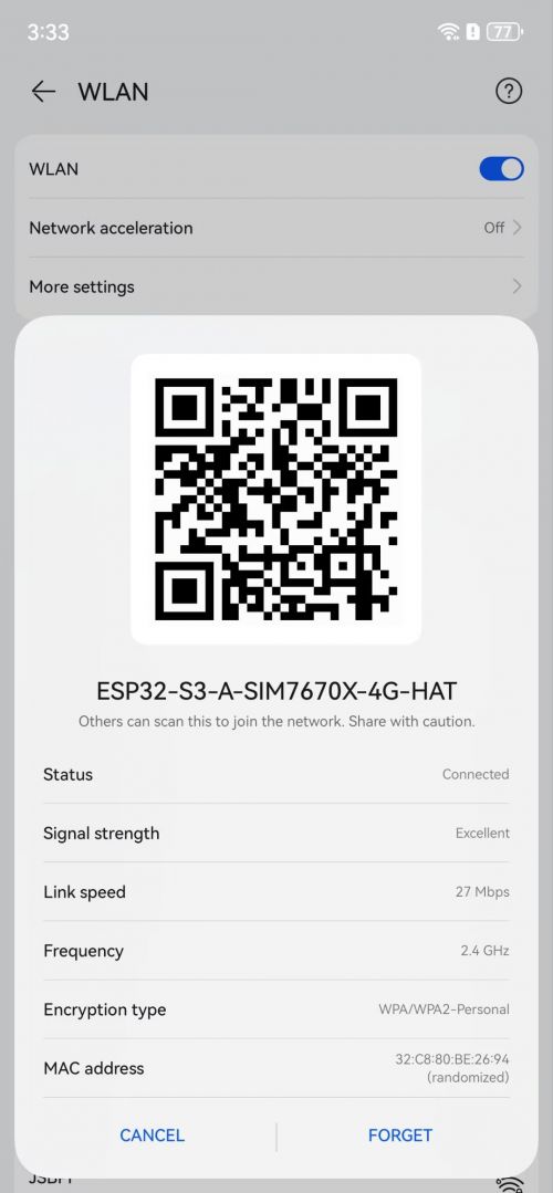
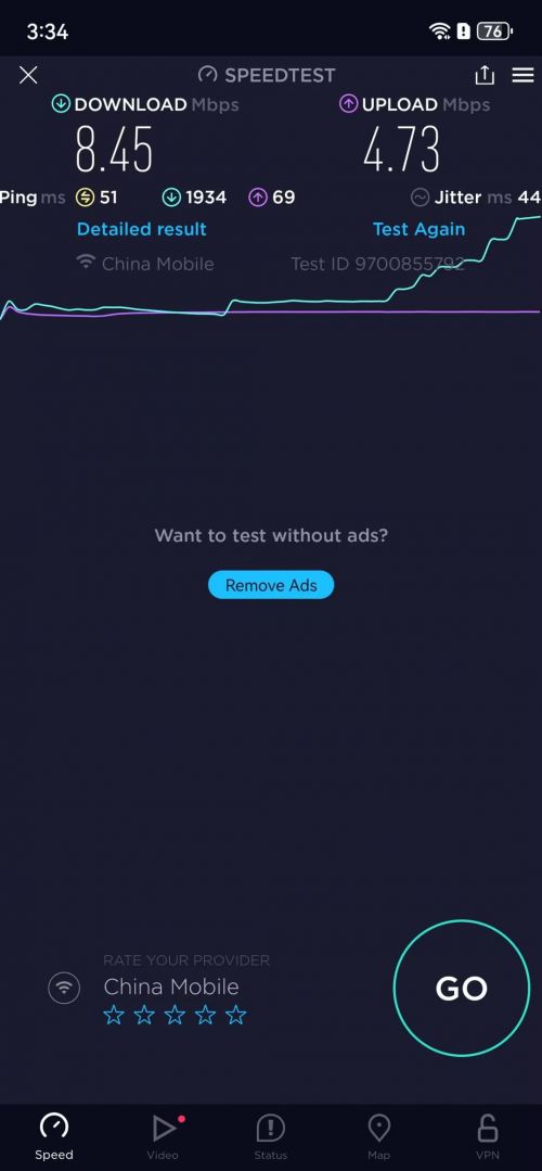
- The back of the development board toggle switch 4G on, USB off, re-power on the development board, wait for the LED display red, open the phone to connect to WIFI: ESP32-S3-A-SIM7670X-4G-HAT, password: 12345678 to access the Internet.
- For more details, you can refer to sample demo.
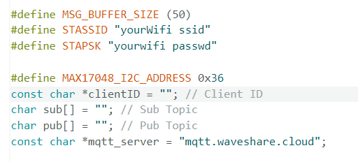
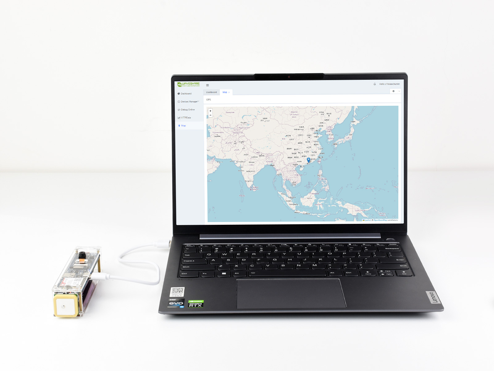
Please download the demo, and open the GNSS-With-WaveshareCloud sample demo.
In this application, communication between ESP32-S3 and A7670E-FASE is established using ESP32-S3's software serial port. By sending AT commands, the GNSS (Global Navigation Satellite System) is activated, and NMEA GNSS data is parsed and uploaded to the Waveshare Cloud. The specific location of the development board is then displayed on a web view map page.
Here, we take the map service provided by Waveshare Cloud as an example:
1. Through Device|Attribute to create any devices, and obtain the MQTT connection data.
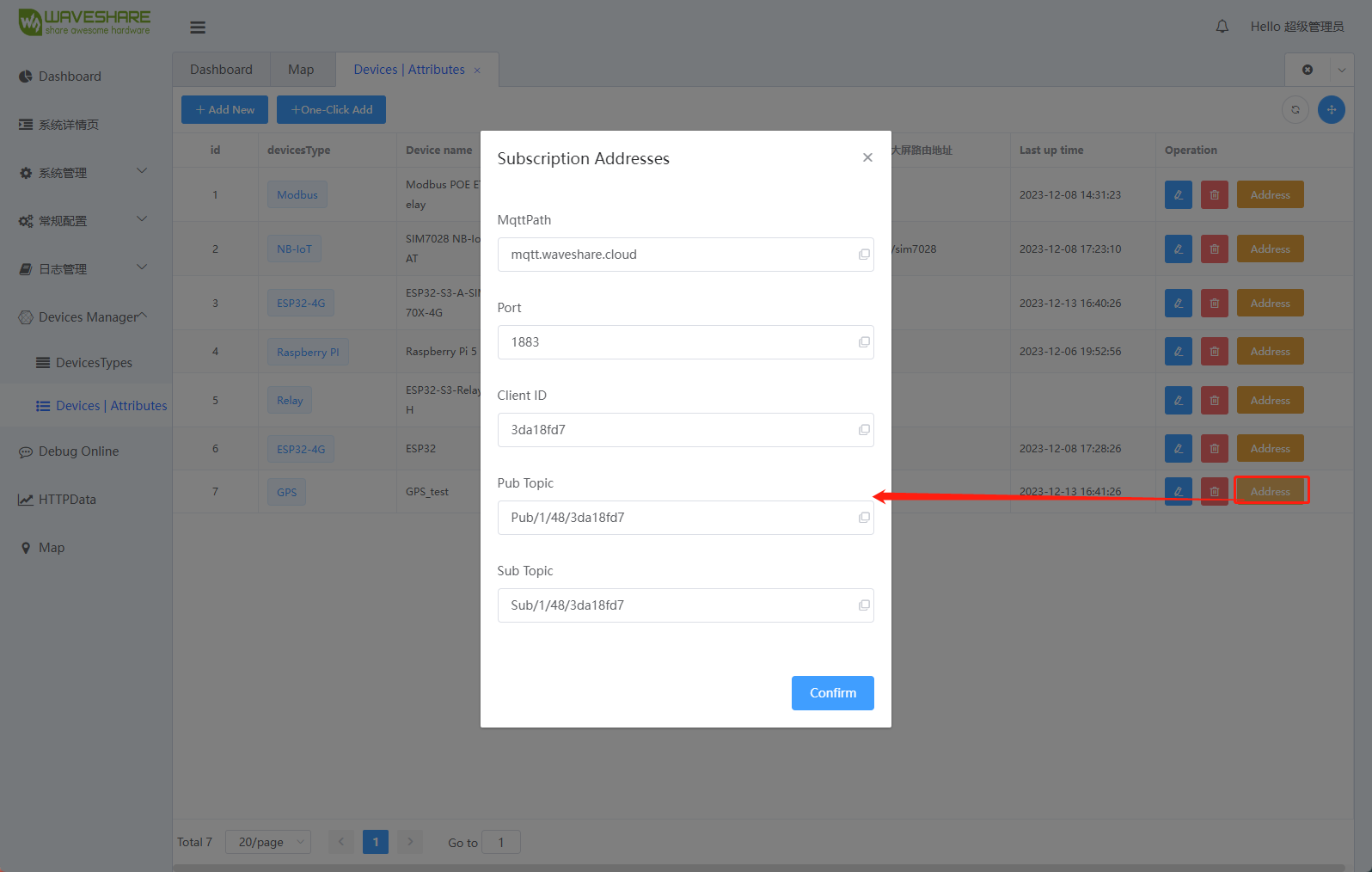
2. Enter the parameters in the GNSS-With-WaveshareCloud demo.
Resource
Document
- Schematic
- MicroPython Development Document
- ESP32 Arduino Core's documentation
- Arduino-Esp32
- ESP-IDF
- 3D drawing
Demo
Tools & Driver
Application Note
- ESP32-S3 Datasheet
- SIM7672X SIM7652X Series FTP(S) Application Note V1.00
- SIM7672X SIM7652X Series HTTP(S) Application Note V1.00
- SIM7672X SIM7652X Series MQTT(S) Application Note V1.00
- SIM7672X SIM7652X Series NETWORK Application Note V1.00
- SIM7672X SIM7652X Series SSL Application Note V1.00
- SIM7672X SIM7652X Series Sleep Mode Application Note V1.00
- SIM7672X SIM7652X Series TCPIP Application Note V1.00
- SIM7672X SIM7652X Series UART Application Note V1.00
- SIM7672X SIM7652X Series UIM HOT SWAP Application Note V1.00
- SIM7672X Series Hardware Design V1.01
- SIM7672 Series SPEC Preliminary 230518
- SIM7672 Series Spec 231205
- SIM767XX Series AT Command Manual V1.01
- SIM767XX V1.01 KDL(230309)
FAQ
The functions of each dip switch are as follows:
ESP32-S3 can perform PPP dial-up internet using both serial port and USB. In this example, TinyUSB protocol is utilized, and USB enumeration addresses are used for dial-up internet.
The code in this example is compiled and flashed using esp-idf. If using Arduino IDE, porting of TinyUSB and handling of PPP packets will be necessary.
The code in this example is compiled and flashed by esp-idf. To modify ESP32-S3 dial-up code, Arudino IDE needs to be ported tinyUSB and ppp packet processing, etc.
We do not assist in modifying the code, please do it yourself.
Currently, the development board connects to the A/SIM7670X 4G module's serial port using software serial port. After enabling GNSS functionality with AT commands, the module outputs satellite signal data through its serial port. AT command can also be sent to the serial port at the moment. Execute the Publish command to publish the required data and filtering of NMEA signal data is required for listening to the returned values from the platform.
The default setting is null for the portable WiFi demo, if the module can't recognize the SIM card APN operator automatically, you need to modify the provided source code, refer to README.md in the directory of ESP32-S3-A-SIM7670X-4G-example.
The specific steps are as follows:
1. Refer to the ESP-IDF chapter of the development environment configuration, install the ESP-IDF development environment and vscode programming tools.
2. Use vscode to open the example program and enter menuconfig to set APN manually.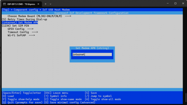
3. Upload the demo to the development board, power off, and reboot the development board.
All the example demos provided use libraries downloaded and installed from the Arduino IDE library. These library files are constantly being updated and iterated upon, so often a library might be missing and can be directly downloaded and installed in the Arduino IDE.
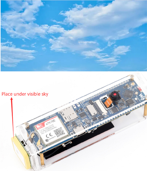
Plug in the GPS antenna to the GNSS antenna socket and place the receiver label face down in an open outdoor area (note that it can't be tested in cloudy and rainy weather), and you need to wait for about 1 minute to receive the positioning signal when powering on;
- This is not readily available sample demo, please program yourself and achieve it by secondary development.
- This Module only provides data connection, ESP32 capture camera side is a video stream, this video stream is temporarily displayed in html, that is, directly displayed on the web page!
- If the video stream data through the module can be mapped out to achieve the function of map transmission; the theory is no problem; need to build a public IP server and so on.
Please configure as shown below: 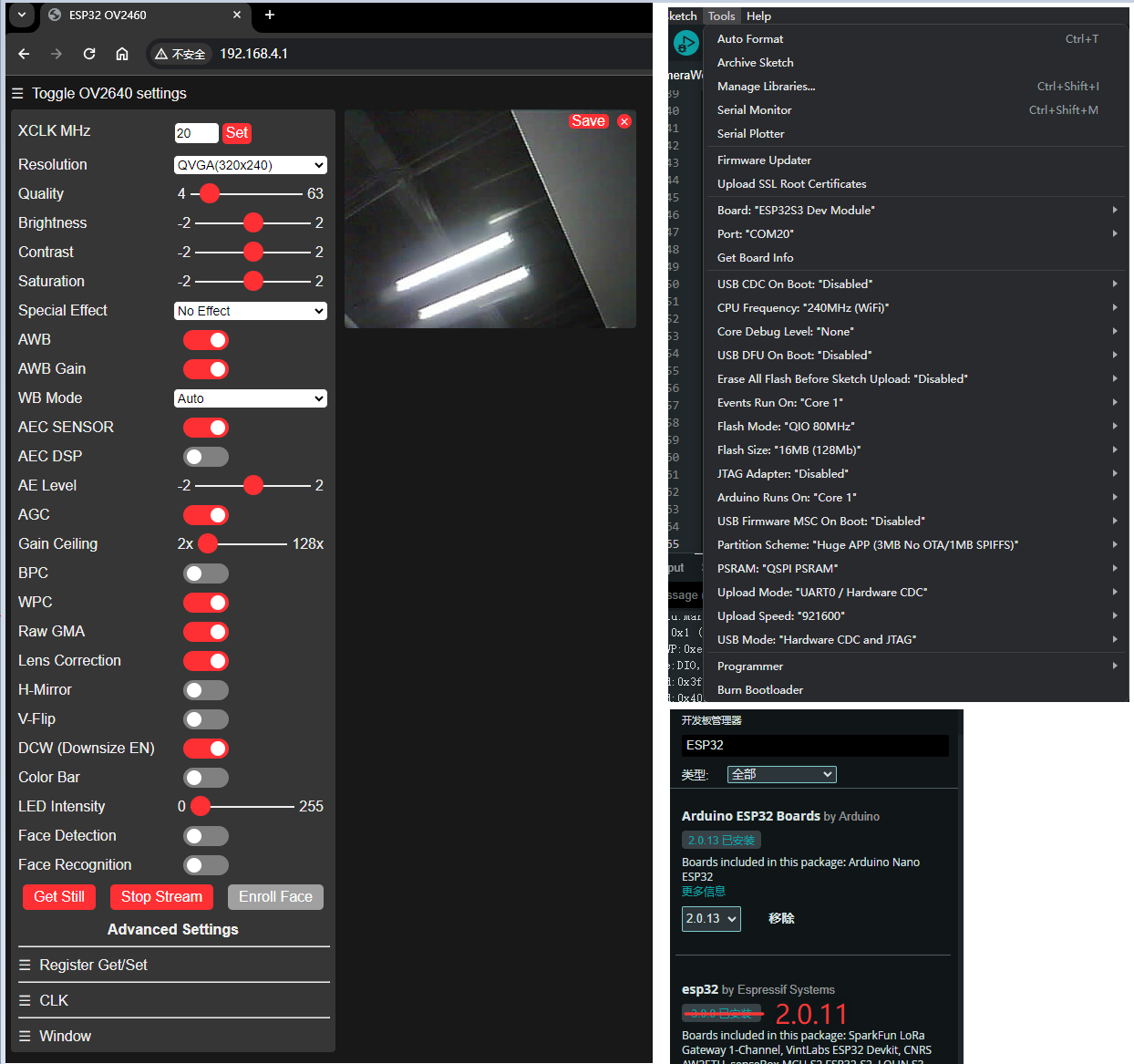
To realize the hotspot function:
0) X7670X to register to the network and successfully dial up to the Internet
1) Turn on the 4G dip switch on the back of the board, turn off the USB, and re-power on the board.
2) Correctly download the corresponding firmware, don't confuse the A7670 and SIM7670 firmware, remember to check the box.
(1) the first time on the battery (that is, after the installation of the battery) need to be connected to the power supply to activate the protection mechanism (this mechanism is to prevent the reverse connection), the battery is fully charged, you can not need to connect the power supply!
(2) In addition, it can also be discharged to activate, typec interface in addition to charging, but also for external equipment power supply, so that the module to external equipment power supply to achieve the purpose of discharging, but also activated!
Support
Monday-Friday (9:30-6:30) Saturday (9:30-5:30)
Email: services01@spotpear.com

[Tutorial Navigation]
- Overview
- Working with ESP-IDF
- Environment Setup
- Run the First ESP-IDF Demo
- New Project
- Create Demo
- Modify COM port
- Modify driver object
- Introduction to other status bar functions
- Compile, flash and serial port monitor
- Use the IDF demos
- Demo
- Cat-1 Module Command Set
- Demo Explaination
- Resource
- FAQ
- Question:What are the functions of each dip switch?
- Question: How does ESP32-S3 dial-up internet using the 4G module's USB in the example?
- Question: How can the ESP32-S3 dial-up internet code be modified?
- Question:How to modify the ESP32-S3 dial-up code?
- Question:Can you assist with code modification?
- Question: Can the module itself connect to WaveshareCloud and report latitude and longitude data?
- Question:Does the camera included in the package support auto-focus?
- Question:For the portable WiFi demo, how to set module APN manually by selecting different operators?
- Question:Why is it common to encounter situations where header files are missing when using the provided dmeos? Can library files be provided?
- Question:What if I can't receive the GPS signal and don't get the location information?
- Question:Does this development board have any demos to remotely transmit the video from the camera over 4g?
- Question:Why is the camera screen black?
- Question:Why does the corresponding hotspot not appear after burning the AP sample program?
- Question:Can the ESP32-S3-SIM7670G-4G be turned on with the battery when it is not connected to the power supply?
- Support