- sales/support
Google Chat:---
- sales
+86-0755-88291180
- sales01
sales@spotpear.com
- sales02
dragon_manager@163.com
- support
tech-support@spotpear.com
- CEO-Complaints
zhoujie@spotpear.com
- sales/support
WhatsApp:13246739196
- HOME
- >
- ARTICLES
- >
- Common Moudle
- >
- ESP
ESP32 S3 4.3inch Touch LCD User Guide
Overview
Introduction
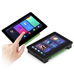
ESP32-S3-Touch-LCD-4.3B is a microcontroller development board with 2.4GHz WiFi and BLE 5 support, and integrates high-capacity Flash and PSRAM. The onboard 4.3-inch capacitive touch screen can smoothly run GUI demos such as LVGL. Combined with various peripheral interfaces (such as CAN, I2C and RS485), it is suitable for the quick development of the HMI and other ESP32-S3 applications. With a wide range of functions and interfaces, it can meet power consumption requirements in Internet of Things (IoT), mobile devices, smart home and other applications.
Features
- Equipped with Xtensa 32-bit LX7 dual-core processor, up to 240MHz main frequency.
- Supports 2.4GHz Wi-Fi (802.11 b/g/n) and Bluetooth 5 (LE), with an onboard antenna.
- Built-in 512KB of SRAM and 384KB ROM, with onboard 8MB PSRAM and 8MB Flash.
- Onboard 4.3inch capacitive touch display, 800×480 resolution, 65K color.
- Supports capacitive touch control via I2C interface, 5-point touch with interrupt support.
- Onboard CAN, RS485, I2C interface, and Micro SD card slot, integrate full-speed USB port.
- Supports flexible clock, module power supply independent setting, and other controls to realize low power consumption in different scenarios.
Hardware Description
Onboard Interface
- CAN interface: Transceiver control, data analysis, acquisition and monitoring of CAN bus networks.
- I2C interface: ESP32-S3 provides multi-lane hardware I2C, currently uses GPIO8(SDA) and GPIO9(SCL) pins as I2C bus for loading IO expansion chip, touch interface and I2C interface.
- RS485 interface: the development board onboard RS485 interface circuits for directly connecting to RS485 device communication, and support automatic switching of RS485 circuit transceiver mode.
- Isolated IO interface: Isolated IO is composed of digital output, digital input and input signal common terminal, IO level up to 5~36V.
- PH2.0 battery header: The development board utilizes the efficient charge and discharge management chip CS8501. It can boost a single-cell lithium battery to 5V. Currently, the charging current is set at 580mA, and users can modify the charging current by replacing the R45 resistor. For more details, you can refer to schematic.
| ESP32-S3-WROOM-x | LCD | USB | SD | UART | CAN | RTC | DO/DO |
| GPIO0 | G3 | ||||||
| GPIO1 | R3 | ||||||
| GPIO2 | R4 | ||||||
| GPIO3 | VSYNC | ||||||
| GPIO4 | TP_IRQ | ||||||
| GPIO5 | DE | ||||||
| GPIO6 | |||||||
| GPIO7 | PCLK | ||||||
| GPIO8 | TP_SDA | ||||||
| GPIO9 | TP_SCL | ||||||
| GPIO10 | B7 | ||||||
| GPIO11 | MOSI | ||||||
| GPIO12 | SCK | ||||||
| GPIO13 | MISO | ||||||
| GPIO14 | B3 | ||||||
| GPIO15 | CANTX | ||||||
| GPIO16 | CANRX | ||||||
| GPIO17 | B6 | ||||||
| GPIO18 | B5 | ||||||
| GPIO19 | USB_DN | ||||||
| GPIO20 | USB_DP | ||||||
| GPIO21 | G7 | ||||||
| GPIO38 | B4 | ||||||
| GPIO39 | G2 | ||||||
| GPIO40 | R7 | ||||||
| GPIO41 | R6 | ||||||
| GPIO42 | R5 | ||||||
| GPIO43 | RS485_RX | ||||||
| GPIO44 | RS485_TX | ||||||
| GPIO45 | G4 | ||||||
| GPIO46 | HSYNC | ||||||
| GPIO47 | G6 | ||||||
| GPIO48 | G5 | ||||||
| CH422G | - | - | - | - | - | - | - |
| EXIO0 | DI0 | ||||||
| EXIO1 | TP_RST | ||||||
| EXIO2 | DISP | ||||||
| EXIO3 | LCD_RST | ||||||
| EXIO4 | SD_CS | ||||||
| EXIO5 | DI1 | ||||||
| OD0 | DO0 | ||||||
| OD1 | DO1 |
Hardware Connection
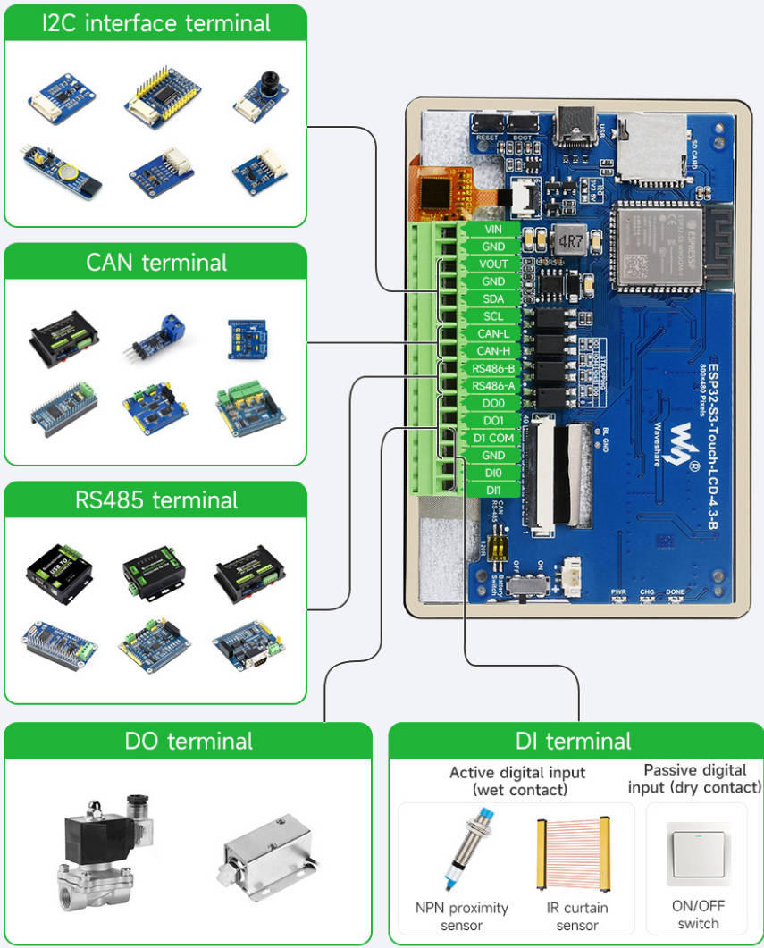
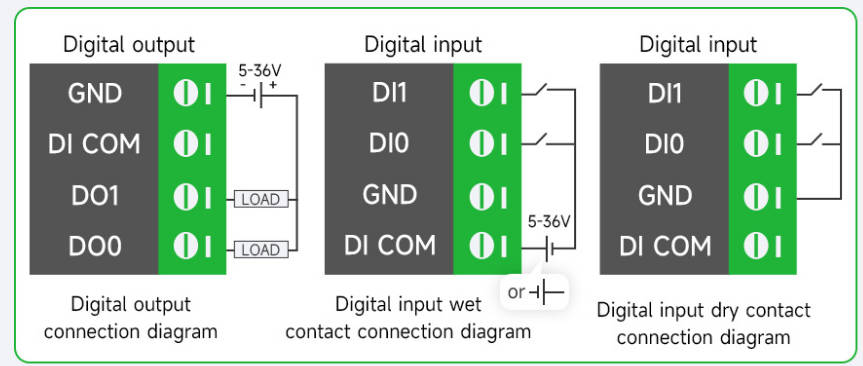
- The development board supports downloading the demo through USB. If the port cannot be identified, please enter the boot mode (press the boot key, connect the board to your PC and then release the boot key). After downloading the demo, press RESET key to run the demo.
- Please pay attention not to put metal or plastic materials to close the PCB antenna.
- The development board adapts the peripheral pin headers such CAN/I2C/RS485/isolated IO interface through 3.5mm screw terminal.
- The 4.3inch LCD occupies most of GPIO pin headers, and the development board adopts CH422G chip to expand IO for reset, backlight control, etc.
- CAN and RS485 peripheral interface does not connect to 120 ohm resistor through the switch by default, and you can switch it on to enable the terminal resistor connection.
- The TF card adopts the SPI connection, please note that the SD_CS pin needs to be driven by the EXIO4 of CH422G chip.
- The isolated IO is controlled by the CH422G chip. For more details, you can refer to IO_Test example. To learn the driving principle, you can refer to #Demo.
Notes
- Currently, running the LVGL benchmark example on ESP-IDF v5.3 with a single core has an average frame rate limit of 26, corresponding to an interface frame rate of 41 (PCLK 21 MHz). Before compiling, you need to configure ESP32 and LVGL through menuconfig.
CONFIG_FREERTOS_HZ=1000
CONFIG_ESP_DEFAULT_CPU_FREQ_MHZ_240=y
CONFIG_ESPTOOLPY_FLASHMODE_QIO=y
CONFIG_ESPTOOLPY_FLASHFREQ_120M=y [should align with PSRAM]
CONFIG_SPIRAM_MODE_OCT=y
CONFIG_IDF_EXPERIMENTAL_FEATURES=y and CONFIG_SPIRAM_SPEED_120M=y [should align with FLASH]
CONFIG_SPIRAM_FETCH_INSTRUCTIONS=y
CONFIG_SPIRAM_RODATA=y
CONFIG_ESP32S3_DATA_CACHE_LINE_64B=y
CONFIG_COMPILER_OPTIMIZATION_PERF=y
#The following LVGL configuration can improve the frame rate (LVGL v8.3):
#define LV_MEM_CUSTOM 1 or CONFIG_LV_MEM_CUSTOM=y
#define LV_MEMCPY_MEMSET_STD 1 or CONFIG_LV_MEMCPY_MEMSET_STD=y
#define LV_ATTRIBUTE_FAST_MEM IRAM_ATTR or CONFIG_LV_ATTRIBUTE_FAST_MEM=y
- For more details about LCD and LVGL performance, you can refer to this document.
- The PH2.0 lithium battery socket only supports single-cell 3.7V lithium batteries. Do not use multiple battery packs for charging and discharging simultaneously. It is recommended to use a single-cell battery with a capacity of below 2000mAh.
- Please note that the CH422G of the board and touch functionality has used the following slave addresses, so do not use the I2C devices with the same slave addresses as below:
    0  1  2  3  4  5  6  7  8  9  a  b  c  d  e  f
00: -  -  -  -  -  -  -  -  -  -  -  -  -  -  -  -
10: -  -  -  -  -  -  -  -  -  -  -  -  -  -  -  -
20: 20 21 22 23 24 25 26 27 -  -  -  -  -  -  -  -
30: 30 31 32 33 34 35 36 37 38 39 3a 3b 3c 3d 3e 3f
40: -  -  -  -  -  -  -  -  -  -  -  -  -  -  -  -
50: -  51 -  -  -  -  -  -  -  -  -  -  -  -  5d -
60: -  -  -  -  -  -  -  -  -  -  -  -  -  -  -  -
70: -  -  -  -  -  -  -  -  -  -  -  -  -  -  -  -
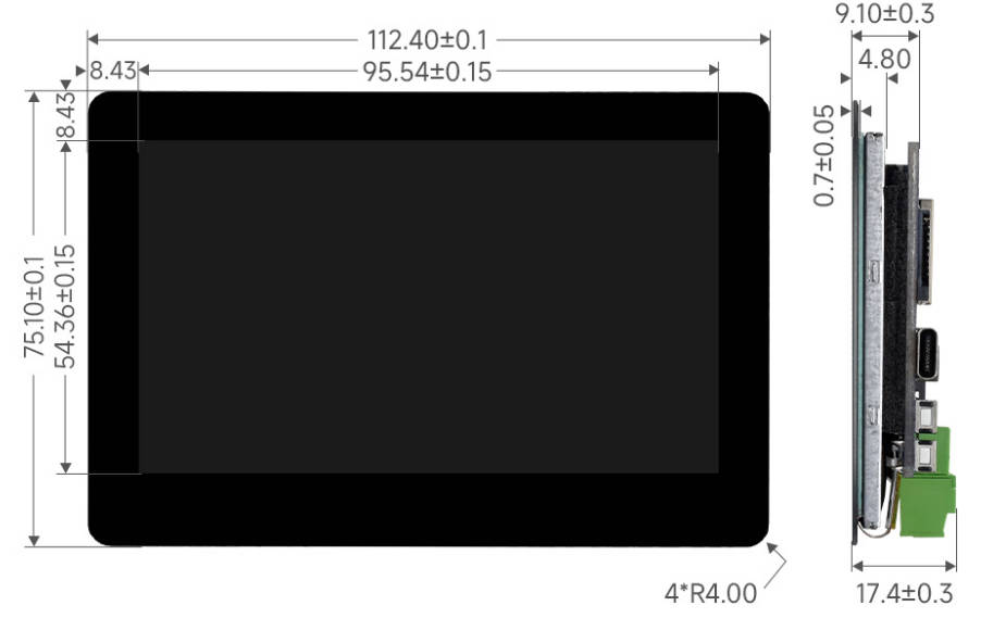
Dimensions
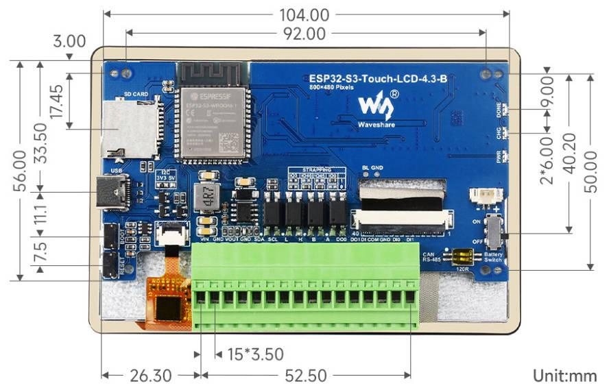
Environment Setting
The software framework for ESP32 series development boards is completed, and you can use MicroPython, and C/C++ (Arduino, ESP-IDF) for rapid prototyping of product development. Here's a brief introduction to these three development approaches:
- Official C/C++ library installation:
- Environment setting is supported on Windows 10. Users can select Arduino/Visual Studio Codes (ESP-IDF) as IDE to develop. For Mac/Linux, users can refer to official introduction.
Arduino
- Download and install Arduino IDE.
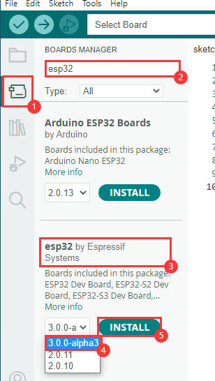
- Install ESP32 on the Arduino IDE as shown below, and you can refer to this link.
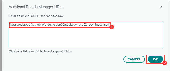
- File -> Preferences -> Additional Boards Managers URLs -> Add the following links:
https://espressif.github.io/arduino-esp32/package_esp32_dev_index.json
- Enter the development board manager, search for "esp32", select version 3.0.0-alpha3 under "esp32 by Espressif Systems" below, and reboot it after installation.
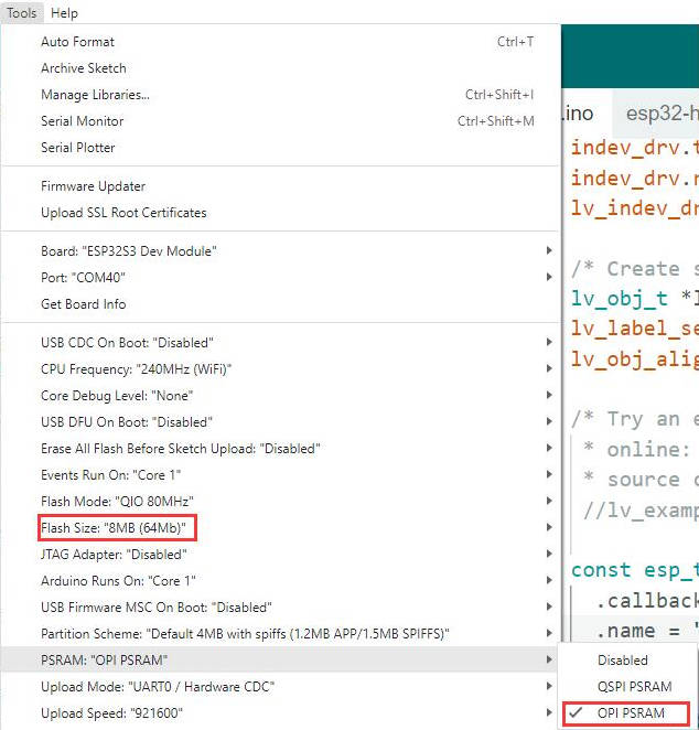
3. Open the Arduino IDE and note that Tools in the menu bar selects the corresponding Flash (8MB) and enables PSRAM (8MB OPI), as shown in the following figure.
Library Installation
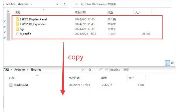
- lvgl libraries require configuration files after installation. It's recommended to directly copy the ESP32_Display_Panel, ESP32_IO_Expander, lvgl file, ESP_Panel_Conf.h, and lv_conf.h file of the ESP32-S3-Touch-LCD-4.3B_libraries to "C:\Users\xxxx\Documents\Arduino\libraries". Please note that "xxxx" represents your computer username.
Sample Demo
Arduino
- Pleas configure as shown below, otherwise the USB port will not output any information:
USB CDC On Boot should be set as Enabled
Flash Size should be set as 16MB(128Mb)
To use the LCD, you should configure as shown below:
USB CDC On Boot should be set as Enabled
Flash Size should be set as 16MB(128Mb)
PSRAM should be set as OPI PSRAM
- Before using the Arduino example, the software library should be set as shown below:
If you install a different version of Arduino esp32, there may be errors, we recommend installing the version we provide for testing and development.
I2C_Test
I2C_Test example, used to test the I2C sockets, this interface connects to GPIO8 (SDA) and GPIO9 (SCL) for I2C communication.
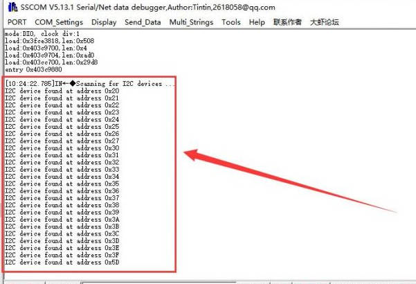
- Use this demo to scan all slave addresses of I2C devices.
- After uploading the demo, connects "HY2.0 2P to DuPont Male 4P 10cm" to the I2C socket. Then connect to the I2C device, open SSCOM, and you can see the scanned I2C addresses.
RS485_Test
RS485_Test example is for testing RS-485 socket. This interface connects to GPIO44(TXD) and GPIO43(RXD) for RS485 communication.
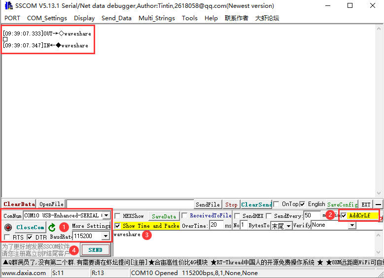
- After uploading the code, the demo needs to use the USB-TO-RS485 converter, connect the RS-485 socket to the "HY2.0 2P to Dupont male 2P 10cm", and then connected to the USB to RS485 converter, USB to RS485 converter connected to the computer.
- Open the SSCOM, send RS485 messages to the ESP32-S3-Touch-LCD-4.3B, ESP32-S3-Touch-LCD-4.3B will send the received message back to the SSCOM, pay attention to the need to select the correct COM port and baud rate, check "AddCrLf " before sending a message.
SD_Test
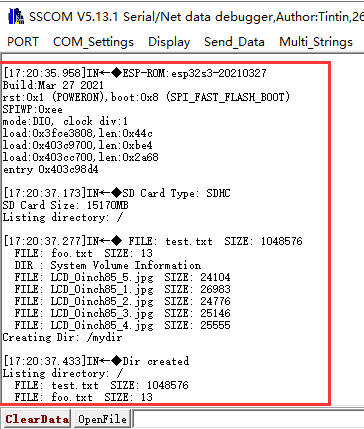
SD_Test is for testing the SD card slot. First, insert the SD card, upload the demo, and then read/write the SD card.
- After uploading the demo, ESP32-S3-Touch-LCD-4.3B will recognize the type and size of the SD card, and then you can operate the files on the SD card:
RTC_Test
RTC_Test example for RTC clock with RTC interrupt.
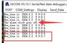
- After burning the code, it will set the time, start the alarm, then read the current time and wait for the alarm to be entered.
- The arrow is to trigger the alarm, the red box is to read the time.
IO_Test
IO_Test example tests the use of isolated IO, and you need to connect DO0 with DI0, DO1 with DI1 first.
- After burning the code, the test passes with a green screen, and the test fails with a red screen.
TWAItransmit
TWAItransmit example is for testing CAN socket, and this interface can connect to GPIO15(TXD) and GPIO16(RXD) for CAN communication.
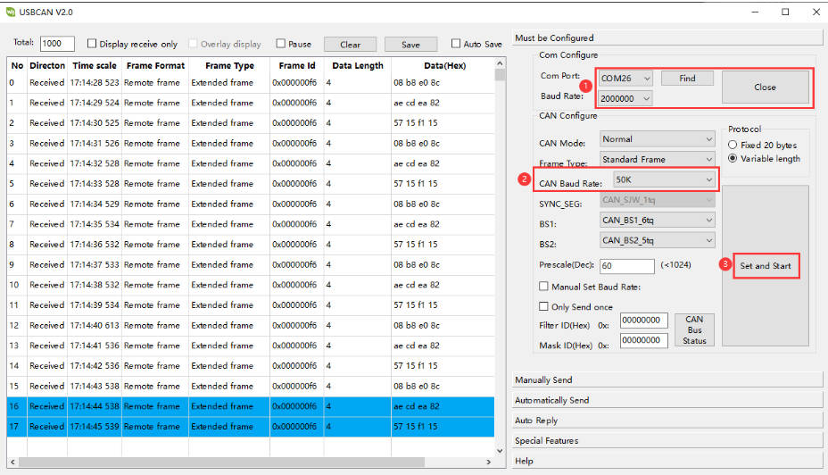
- After programming the code, using the "HY2.0 2P to DuPont male head 2P red-black 10cm" cable, and connect ESP32-S3-Touch-LCD-4.3B to the CAN H and CAN L pins of the USB-CAN-A
- Once you open the serial port debugging assistant, you can observe that the ESP32-S3-Touch-LCD-4.3B has started sending CAN messages.
- Connect the USB-CAN-A to the computer and open the USB-CAN-A_TOOL_2.0. Select the corresponding COM port, set the baud rate to 2000000 as shown in the image, set the CAN baud rate to 50.000Kbps, and you can view the CAN messages sent by the ESP32-S3-Touch-LCD-4.3B.
TWAIreceive
TWAIreceive example is for testing CAN socket, and this interface can connect to GPIO15(TXD) and GPIO16(RXD) for CAN communication.
- After uploading the code, use the "HY2.0 2P to DuPont male head 2P red-black 10cm" cable to connect the ESP32-S3-Touch-LCD-4.3B to the CAN H and CAN L pins of USB-CAN-A
- Connect the USB-CAN-A to the computer and open the USB-CAN-A_TOOL_2.0. Select the corresponding COM port, set the port baud rate to 2000000 as indicated in the image, and set the CAN baud rate to 500.000Kbps. With these settings, you'll be able to send CAN messages to the ESP32-S3-Touch-LCD-4.3B.
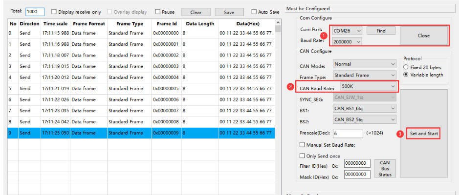
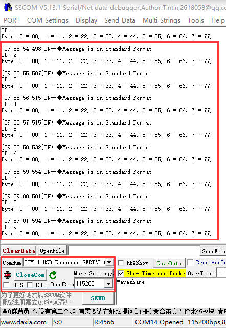
- Open the serial port debugging assistant, send data on USB-CAN-A_TOOL_2.0, and you can see ESP32-S3-Touch-LCD-4.3B starts to receive CAN messages (If there are any reception errors, try resetting the devices multiple times and restarting the software. Please be patient and allow some time for the reception process.)
lvgl_Porting
lvgl_Porting example is for testing RGB touch screen.
- After uploading the code, you can try to make a series of touch screen operation. Also, we provide LVGL porting examples for users (If there's no screen response after burning the code, check if the Arduino IDE -> Tools settings are correctly configured: choose the corresponding Flash (8MB) and enable PSRAM (8MB OPI)).
DrawColorBar
DrawColorBar example is for testing RGB screen.
- After uploading the code, you should observe the screen displaying bands of blue, green, and red colors. (If the screen shows no response after burning the code, check if the Arduino IDE -> Tools settings are correctly configured: choose the corresponding Flash (8MB) and enable PSRAM (8MB OPI)).
Resources
Schematic diagram
Project diagrams
Demo
Datasheets
ESP32-S3
Other components
Software tools
Arduino
VScode
Debugging tool
Other resource link
- ESP32-Arduino official documentation
- ESP32-Arduino official resources
- ESP-IDF official resources
- LVGL official documentation
FAQ
① Restart the COM port in UCANV2.0.exe and press the ESP32-S3-Touch-LCD-4.3B reset button multiple times.
② Uncheck DTR and RTS in the serial port debugging assistant.
If there's no screen response after programming the code, check whether the correct configurations are set in Arduino IDE -> Tools: Choose the corresponding Flash (8MB) and enable PSRAM (8MB OPI).
Check if the "ESP32-S3-Touch-LCD-4.3B-libraries" library is installed. Please refer to installation steps.
I can't retrieve the library file because the path to install the library is in Chinese.
You can refer to the following steps to run the demo for comparison:
- 1) Before running the program, please install the library
- 2) Run and burn original program
To solve this problem, please install the Arduino esp32 v3.0.2-h.
Support
Monday-Friday (9:30-6:30) Saturday (9:30-5:30)
Mobile: +86 13434470212
Email: services01@spotpear.com
[Tutorial Navigation]
- Overview
- Sample Demo
- Resources
- FAQ
- Question:ESP32-S3-Touch-LCD-4.3B CAN reception failure?
- Question:ESP32-S3-Touch-LCD-4.3B shows no response after uploading an Arduino demo for RGB screen displaying?
- Question:ESP32-S3-Touch-LCD-4.3B fails to compile an Arduino demo for the RGB screen and shows errors?
- Question:Why burn lvgl program missing lv_cong.h when all libraries are installed?
- Question:Why is the screen not displaying?
- Question:Why does it show "fatal error:esp_ memory_ utils.h:No such file or directory" when compiling the example with Arduino IDE?
- Support


