- sales/support
Google Chat:---
- sales
+86-0755-88291180
- sales01
sales@spotpear.com
- sales02
dragon_manager@163.com
- support
tech-support@spotpear.com
- CEO-Complaints
zhoujie@spotpear.com
- Only Tech-Support
WhatsApp:13246739196
- Purchase/Shipping/Refund
WhatsApp:13424403025
- HOME
- >
- ARTICLES
- >
- Common Moudle
- >
- ESP
ESP32-P4-Module User Guide
Overview
Introduction
ESP32-P4-Module is a dual-core RISC-V high-performance module based on ESP32-P4 chip designed by Waveshare, using ESP32-C6H8 to expand WIFI6 functionality. It supports a wide range of human-computer interfaces, including MIPI-CSI (Integrated Image Signal Processor, ISP) and MIPI-DSI interfaces, as well as common peripherals such as SPI, I2S, I2C, LED PWM, MCPWM, RMT, ADC, UART, and TWAI™. It also supports USB OTG 2.0 HS, Ethernet, and SDIO Host 3.0 for high-speed connectivity. The chip integrates a digital signature peripheral and a dedicated key management unit to ensure its security. ESP32-P4-Module is specifically designed for high-performance and high-security applications, fully meeting the higher demands of embedded applications for human-machine interface support, edge computing capabilities, and IO connectivity features.
Features
- Processor
- Equipped with RISC-V 32-bit dual-core processor (HP system), it features DSP and instruction set expansion, along with floating point unit (FPU), and the main frequency is up to 400MHz
- Equipped with a RISC-V 32-bit single-core processor (LP system), the main frequency is up to 40MHz
- Equipped with ESP32-C6 WIFI/BT co-processor, expand WIFI 6/Bluetooth 5 and other functions through SDIO
- Memory
- 128 KB of high-performance (HP) system read-only memory (ROM)
- 16 KB of low-power (LP) system read-only memory (ROM)
- 768 KB of high-performance (HP) L2 memory (L2MEM)
- 32 KB of low-power (LP) SRAM
- 8 KB of system tightly coupled memory (TCM)
- 32 MB PSRAM is stacked in the package, and the QSPI port is connected to 16MB Nor Flash
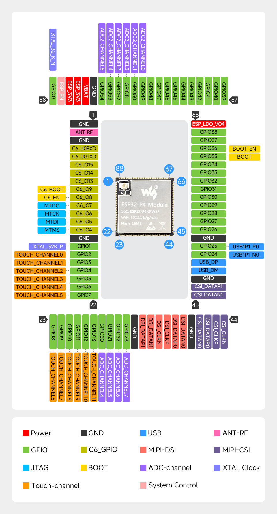
Pinout Definition
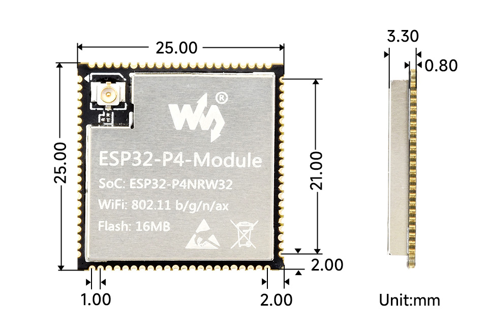
Dimensions
Pinout Description
| 1 | GND | Ground pin | |
| 2 | LNA_OUT | Antenna pin of ESP32-C6, led to the pin pad by default and can be switched to an IPEX Gen 1 antenna holder via a reserved 0R resistor | |
| 3 | GND | Ground pin | |
| 4 | C6_U0RXD | UART RXD of ESP32-C6, for flashing firmware to ESP32-C6 | |
| 5 | C6_U0TXD | UART TXD of ESP32-C6, for flashing firmware to ESP32-C6 | |
| 6 | C6_IO15 | ESP32-C6 GPIO15 | |
| 7 | C6_IO14 | ESP32-C6 GPIO14 | |
| 8 | C6_IO13 | ESP32-C6 GPIO13 | |
| 9 | C6_IO9 | ESP32-C6 GPIO9; If C6_SPIO8 is in pull-up mode, it can enter download mode when pulled down before power-on | C6_BOOT |
| 10 | C6_IO8 | ESP32-C6 GPIO8; It is recommended to pull up 10k resistor to 3.3V | C6_BOOT_EN |
| 11 | C6_IO7 | ESP32-C6 GPIO7; C6 JTAG GPIO | MTDO |
| 12 | C6_IO6 | ESP32-C6 GPIO6; C6 JTAG GPIO | MTCK |
| 13 | C6_IO5 | ESP32-C6 GPIO5; C6 JTAG GPIO | MTDI |
| 14 | C6_IO4 | ESP32-C6 GPIO4; C6 JTAG GPIO | MTMS |
| 15 | GND | Ground pin | |
| 16 | GPIO1 | GPIO1, can be connected with GPIO0 to 32.768KHz crystal oscillator, LP system crystal source | XTAL_32K_P |
| 17 | GPIO2 | GPIO2 | TOUCH_CHANNEL0 |
| 18 | GPIO3 | GPIO3 | TOUCH_CHANNEL1 |
| 19 | GPIO4 | GPIO4 | TOUCH_CHANNEL2 |
| 20 | GPIO5 | GPIO5 | TOUCH_CHANNEL3 |
| 21 | GPIO6 | GPIO6 | TOUCH_CHANNEL4 |
| 22 | GPIO7 | GPIO7 | TOUCH_CHANNEL5 |
| 23 | GPIO8 | GPIO8 | TOUCH_CHANNEL6 |
| 24 | GPIO9 | GPIO9 | TOUCH_CHANNEL7 |
| 25 | GPIO10 | GPIO10 | TOUCH_CHANNEL8 |
| 26 | GPIO11 | GPIO11 | TOUCH_CHANNEL9 |
| 27 | GPIO12 | GPIO12 | TOUCH_CHANNEL10 |
| 28 | GPIO13 | GPIO13 | TOUCH_CHANNEL11 |
| 29 | GPIO20 | GPIO20 | ADC1_CHANNEL4 |
| 30 | GPIO21 | GPIO21 | ADC1_CHANNEL5 |
| 31 | GPIO22 | GPIO22 | ADC1_CHANNEL6 |
| 32 | GPIO23 | GPIO23 | ADC1_CHANNEL7 |
| 33 | GND | Ground pin | |
| 34 | DSI_DATAP1 | MIPI-DSI data signal line | |
| 35 | DSI_DATAN1 | MIPI-DSI data signal line | |
| 36 | DSI_CLKN | MIPI-DSI clock signal line | |
| 37 | DSI_CLKP | MIPI-DSI clock signal line | |
| 38 | DSI_DATAP0 | MIPI-DSI data signal line | |
| 39 | DSI_DATAN0 | MIPI-DSI data signal line | |
| 40 | GND | Ground pin | |
| 41 | CSI_DATAN0 | MIPI-CSI data signal line | |
| 42 | CSI_DATAP0 | MIPI-CSI data signal line | |
| 43 | CSI_CLKP | MIPI-CSI clock signal line | |
| 44 | CSI_CLKN | MIPI-CSI clock signal line | |
| 45 | CSI_DATAN1 | MIPI-CSI data signal line | |
| 46 | CSI_DATAP1 | MIPI-CSI data signal line | |
| 47 | GND | Ground pin | |
| 48 | USB_DM | USB 2.0 high-speed pin | |
| 49 | USB_DP | USB 2.0 high-speed pin | |
| 50 | GPIO24 | GPIO24; USB 2.0 full-speed pin | USB1P1_N0 |
| 51 | GPIO25 | Ground pin; USB 2.0 full-speed pin | USB1P1_P0 |
| 52 | GND | Ground pin | |
| 53 | GPIO26 | GPIO26 | |
| 54 | GPIO27 | GPIO27 | |
| 55 | GPIO28 | GPIO28 | |
| 56 | GPIO29 | GPIO29 | |
| 57 | GPIO30 | GPIO30 | |
| 58 | GPIO31 | GPIO31 | |
| 59 | GPIO32 | GPIO32 | |
| 60 | GPIO33 | GPIO33 | |
| 61 | GPIO34 | GPIO34 | |
| 62 | GPIO35 | GPIO35; If GPIO36 is in pull-up mode, it can enter download mode when pulled down before power-on | BOOT |
| 63 | GPIO36 | GPIO36; It is recommended to pull up 10k resistor to 3.3V | BOOT_EN |
| 64 | GPIO37 | GPIO37 | |
| 65 | GPIO38 | GPIO38 | |
| 66 | ESP_LDO_VO4 | ESP32-P4 internal LDO output pin, default output 1.8V; The output voltage can be controlled by program, controlling the voltage domains of GPIO39~GPIO48 | |
| 67 | GPIO39 | GPIO39 | |
| 68 | GPIO40 | GPIO40 | |
| 69 | GPIO41 | GPIO41 | |
| 70 | GPIO42 | GPIO42 | |
| 71 | GPIO43 | GPIO43 | |
| 72 | GPIO44 | GPIO44 | |
| 73 | GPIO45 | GPIO45 | |
| 74 | GPIO46 | GPIO46 | |
| 75 | GPIO47 | GPIO47 | |
| 76 | GPIO48 | GPIO48 | |
| 77 | GPIO49 | GPIO49 | ADC2_CHANNEL0 |
| 78 | GPIO50 | GPIO50 | ADC2_CHANNEL1 |
| 79 | GPIO51 | GPIO51 | ADC2_CHANNEL2 |
| 80 | GPIO52 | GPIO52 | ADC2_CHANNEL3 |
| 81 | GPIO53 | GPIO53 | ADC2_CHANNEL4 |
| 82 | GPIO54 | GPIO54 | ADC2_CHANNEL5 |
| 83 | GND | Ground pin | |
| 84 | VBAT | ESP32-P4 LP power supply pin, can be connected to a battery, it is recommended to connect to 3.3V by default | |
| 85 | ESP_3V3 | Power supply pin, it is recommended to connect 3.3V by default | |
| 86 | ESP_3V3 | Power supply pin, it is recommended to connect 3.3V by default | |
| 87 | ESP_EN | ESP32-P4 enable pin, default pulled high to enable | |
| 88 | GPIO0 | XTAL_32K_N | GPIO1, can be connected with GPIO0 to 32.768KHz crystal oscillator, LP system crystal source |
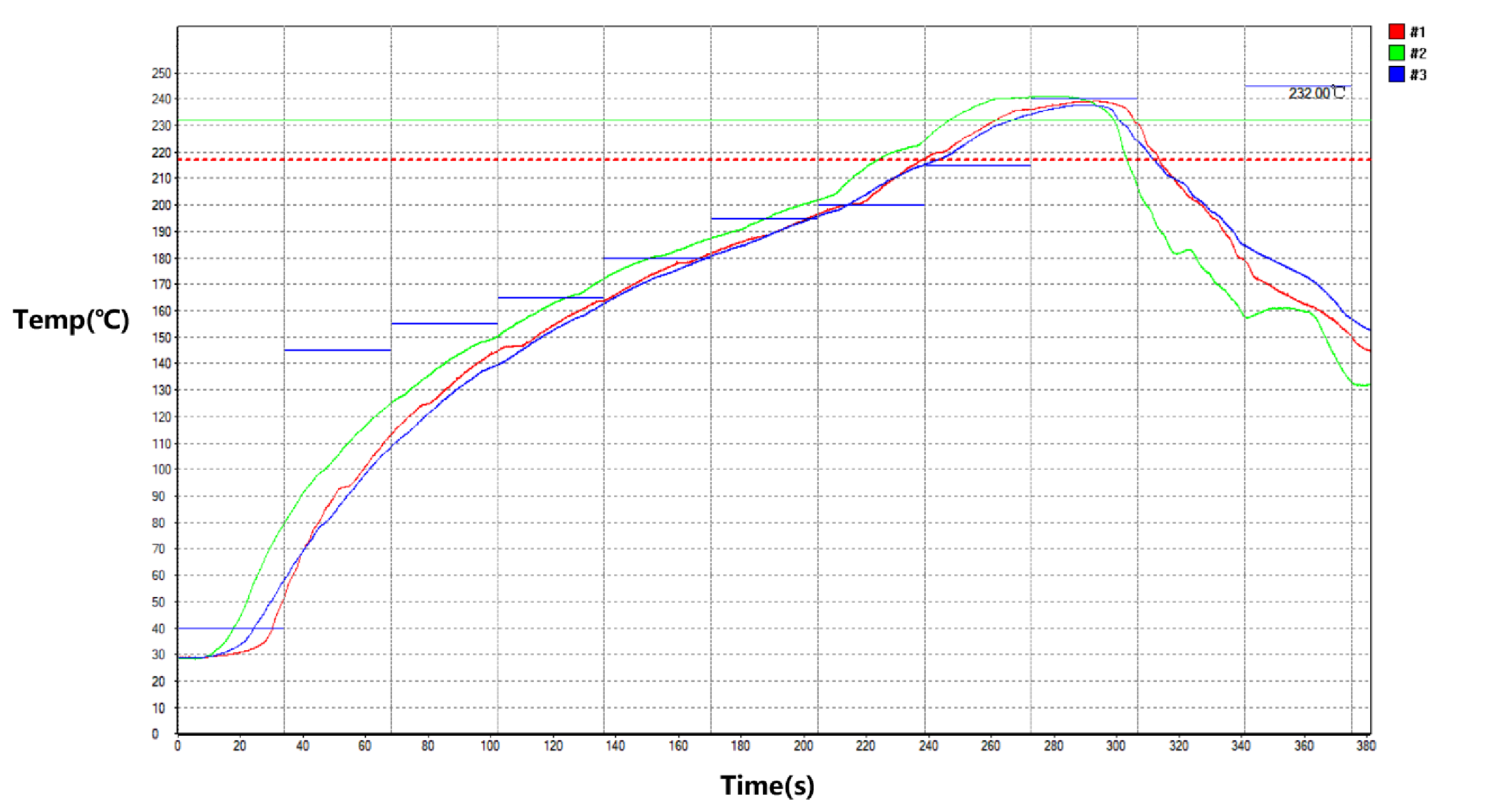
Processing Temperature Curve
- The module is processed using lead-free technology. If there is a secondary SMT processing in the future, it is recommended that the module only undergo reflow soldering once
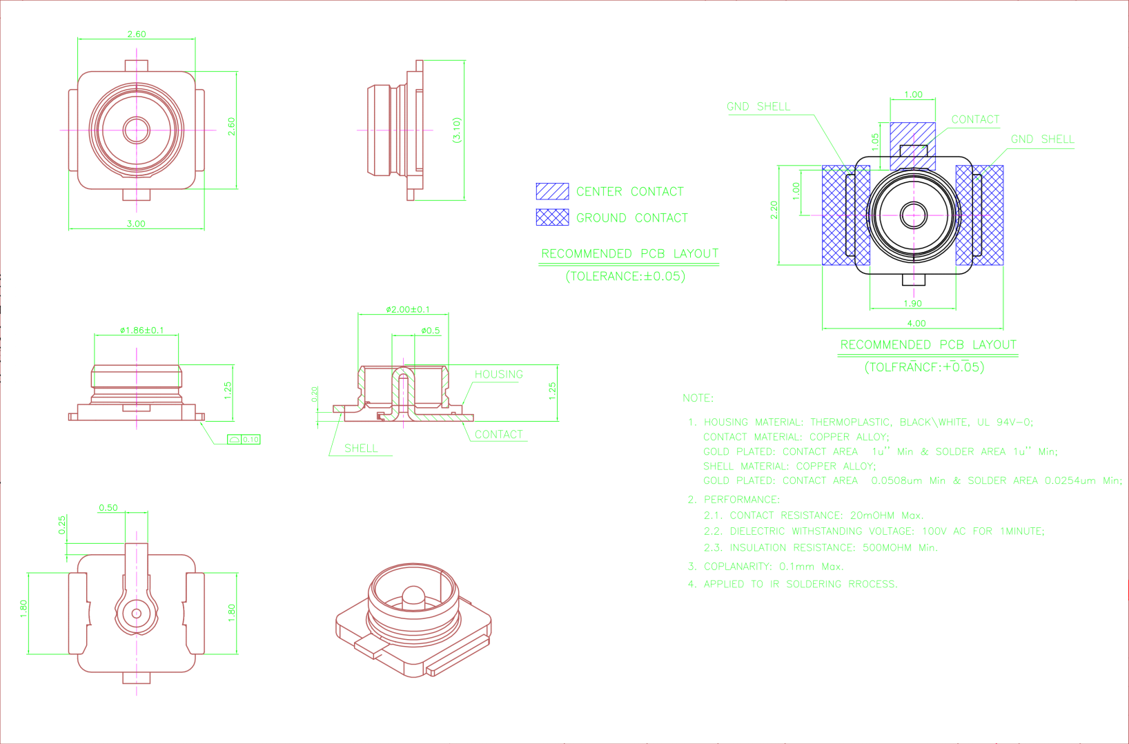
IPEX Gen 1 Antenna Holder Drawing
Resources
Schematic Diagram
3D Diagram
PCB Packaging Drawing
Datasheets
Softwares
FAQ
Support
Monday-Friday (9:30-6:30) Saturday (9:30-5:30)
Email: services01@spotpear.com