


- sales/support
Google Chat:---
- sales
+86-0755-88291180
- sales01
sales@spotpear.com
- sales02
dragon_manager@163.com
- support
tech-support@spotpear.com
- CEO-Complaints
zhoujie@spotpear.com
- Only Tech-Support
WhatsApp:13246739196
- Purchase/Shipping/Refund
WhatsApp:13424403025
- HOME
- >
- ARTICLES
- >
- Common Moudle
- >
- ESP
ESP-S3-1.69-touch User Guide
Overview
Introduction
ESP32-S3-LCD-1.69 is a low-cost, high-performance MCU board designed by Waveshare, embedded with 240MHz dual-core processor, tiny size, with onboard 1.69inch 262K LCD display, Lithium battery recharge manager, 6-axis sensor (3-axis accelerometer and 3-axis gyroscope), WiFi/Bluetooth antenna, RTC, and so on, which makes it easy for you to develop and integrate it into products quickly.
Features
- Equipped with high-performance Xtensa®32-bit LX7 dual-core processor, main frequency running up to 240MHz.
- Support 2.4 GHz Wi-Fi (802.11 b/g/n) and Bluetooth® 5 (LE), and onboard antenna.
- Built-in 512KB SRAM and 384KB ROM, 8MB PSRAM, and external 16MB Flash.
- Onboard 1.69-inch capacitive touch LCD screen, 240×280 resolution, 262K colors, can clearly display color pictures.
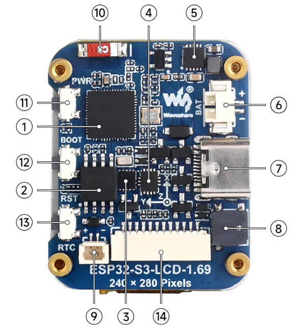
Hardware Description
- Onboard patch antenna, uses 0 ohm shorted optional external antennas, as shown in ⑩.
- Onboard PCF85063 RTC chip with reserved SH1.0 RTC battery header (support charging), supports timing function, as shown in ③ and ⑨.
- Onboard QMI8658C 6-axis Inertial Measurement Unit (IMU), including a 3-axis gyroscope and a 3-axis accelerator, as shown in ④.
- Onboard ETA6098 high-performance Lithium battery charging chip, M1.25 Lithium battery interface, easy to install lithium batteries charge and discharge for long-term usage, as shown in ⑤ and ⑥.
- Onboard buzzer can be utilized as an audio peripheral, as shown in ⑧.
- Onboard Type-C interface, connect to ESP32-S3 USB for demo programming and log printing, as shown in ⑦.
- Onboard BOOT and RST function buttons, easy to reset and enter the download mode, as shown in ⑫ and ⑬.
- Onboard function circuit button, can be customized as the power-on button, and can identify single pressing, double pressing, and long pressing, as shown in ⑪.
Pinout Definition
When using the GPIO header reserved on the ESP32-S3-LCD-1.69 board, please pay attention to the wiring colors and corresponding functions.
Please avoid wrong wiring as it may cause the burning of the board.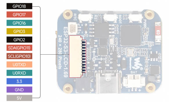
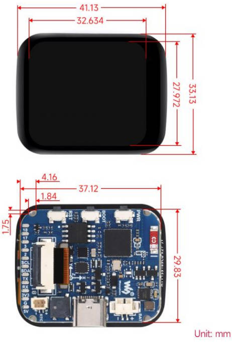
Dimensions
LCD Description
LCD & Controller
- The built-in controller of this LCD is ST7789V2, which is an LCD controller with 240 × RGB × 320 pixels, and the pixels of this LCD are 240(H) × RGB × 280(V), so you can see the internal RAM of this LCD is not fully used.
- The LCD supports 12-bit, 16-bit, and 18-bit per pixel input color formats, i.e., RGB444, RGB565, and RGB666, and this demo uses the RGB565 color format, which is also the commonly used RGB format.
- The LCD adopts the 4-wire SPI communication interface, which can greatly reduce GPIO ports and the communication speed is faster.
- The resolution of this module is 240(H) × RGB × 280(V). As its four corners are round (#Dimensions), some of the input images will be partially undisplayed.
Communication Protocol
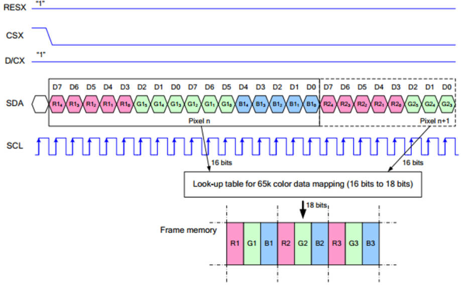
Note: The difference from the traditional SPI protocol is that the data line sent from the slave to the host is hidden because it only needs to be displayed. Please refer to Datasheet Page 66 for the table.
RESX is reset, it is pulled low when the module is powered on, usually set to 1;
CSX is the slave chip select, and the chip will be enabled only when CS is low.
D/CX is the data/command control pin of the chip, when DC = 0, write command, when DC = 1, write data.
SDA is the transmitted data, that is, RGB data;
SCL is the SPI communication clock.
For SPI communication, data is transmitted with timing, that is, the combination of clock phase (CPHA) and clock polarity (CPOL):
The level of CPHA determines whether the serial synchronization clock is collected on the first clock transition edge or the second clock transition edge. When CPHA = 0, data acquisition is performed on the first transition edge;
The level of CPOL determines the idle state level of the serial synchronous clock. CPOL = 0, which is a low level.
As can be seen from the figure, when the first falling edge of SCLK starts to transmit data, 8-bit data is transmitted in one clock cycle, using SPI0, bit-by-bit transmission, high-order first, and low-order last.
Sample Demo
Arduino IDE
Environment Setup
Install Arduino IDE
- Open the official website software download interface, select the corresponding system and system bits to download
- You can choose to download directly, or you can choose to contribute and download
- Run the installer and install all by default
Install arduino-esp32 online
- Open Preferences File -> Preferences
- Add the corresponding board management link and click this button
- In the first blank space, add the following
https://espressif.github.io/arduino-esp32/package_esp32_index.json
- Save the setup
- Open the board manager and search for ESP32, select version 3.0.5 or above
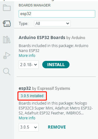
- Wait for the download. Note: The download time is long, please be patient
- The arduino-esp32 download is complete
Run library installation
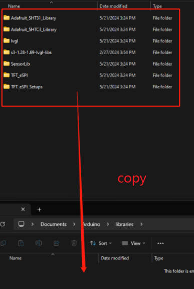
When using the LVGL library, you need to modify the configuration of the corresponding screen. It is recommended to use the lib library in the demo directly. Copy the library folder to the C:\Users\xxxx\Documents\Arduino\libraries directory. xxxx represents the user name on your computer, so be careful. When copying a library, please note that if there are other libraries in the directory, please clean or migrate them first to avoid replacement or library conflicts
| File name | Description | Version | Can it be downloaded directly? |
|---|---|---|---|
| GFX_Library_for_Arduino | ST7789 GFX graphical library | v1.4.9 | Yes |
| lvgl | LVGL graphical library | v8.4.0 | Yes. Demos folder needs to be copied to src after downloading, it is recommended to use existing library |
| Mylibrary | development board pin macros definition | —— | —— |
| SensorLib | PCF85063 and QMI8658 sensor driver library | v0.2.1 | Yes |
| lv_conf.h | LVGLconfiguration file | —— | —— |
Get started
- Use the TYPT-C to TYPE-A cable to connect the development board to the computer
- The Arduino IDE board searches for waveshare esp32-s3-lcd-1.69 and specifies the COM port
Hello World example
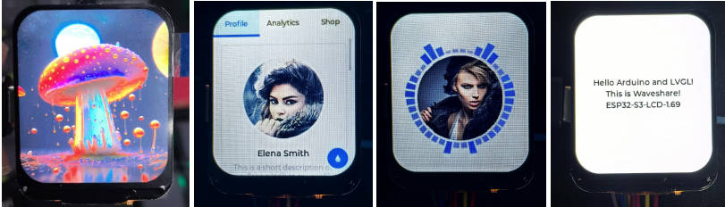
This example demonstrates how to control the ST7789 display using the Arduino GFX library and the Arduino DriveBus library, demonstrating basic graphics library functionality with dynamically changing text. This code can also be used to test the basic performance of the display and the display of random text.
Key code snippets
1. Display initialization:
if (!gfx->begin()) {
  USBSerial.println("gfx->begin() failed!");
}
2. Clear the screen and display text:
gfx->fillScreen(BLACK);
gfx->setCursor(10, 10);
gfx->setTextColor(RED);
gfx->println("Hello World!");
3. The animation shows:
gfx->setCursor(random(gfx->width()), random(gfx->height()));
gfx->setTextColor(random(0xffff), random(0xffff));
gfx->setTextSize(random(6), random(6), random(2));
gfx->println("Hello World!");
GFX AsciiTable example
This example shows how to display a basic ASCII character table on an ST7789 display on an ESP32 using the Arduino GFX library. The core function of the code is to initialize the display screen and print ASCII characters in rows and columns on the display screen according to the screen size.
GFX PCF85063 simpleTime example
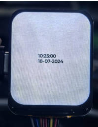
This example demonstrates using the PCF85063 RTC module to display the current time on an ST7789 display, retrieving the time every second and updating the display only when the time changes.
GFX ESPWiFiAnalyzer example
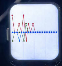
This example demonstrates an example of plotting WiFi band signal strength on the ST7789 display to implement the function of a WiFi analyzer.
GFX Clock example
This example demonstrates a simple ST7789 clock example implemented with simple tag pointers and time management.
Key code snippets
1 Drawing of hour, minute and second hands
void redraw_hands_cached_draw_and_erase() {
    gfx->startWrite();
    draw_and_erase_cached_line(center, center, nsx, nsy, SECOND_COLOR, cached_points, sHandLen + 1, false, false);
    draw_and_erase_cached_line(center, center, nhx, nhy, HOUR_COLOR, cached_points + ((sHandLen + 1) * 2), hHandLen + 1, true, false);
    draw_and_erase_cached_line(center, center, nmx, nmy, MINUTE_COLOR, cached_points + ((sHandLen + 1 + hHandLen + 1) * 2), mHandLen + 1, true, true);
    gfx->endWrite();
}
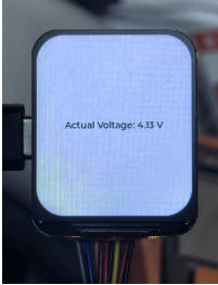
LVGL Measuring voltage example
The board is reserved for voltage measurement by dividing the voltage. Use GPIO1 to read the analog value and obtain the battery voltage through the voltage dividing formula.
Effect demonstration
LVGL PCF85063 simpleTime example
This example demonstrates using the PCF85063 RTC module to display the current time on the ST7789 display under LVGL, retrieving the time every second and updating the display only when the time changes. The comparison time refresh effect is better
Effect demonstration
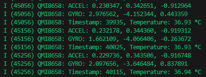
LVGL QMI8658 ui example
This example demonstrates the use of LVGL for graphics display, communicating with the QMI8658 IMU to obtain accelerometer and gyroscope data
Effect demonstration
PWR_Key
This function button is designed to solve the problem that peripheral buttons have few functions. The working principle is as follows:
After pressing the PWR, the battery can be powered, and when the system starts, the system should define GPIO35 to continuously output a high level to maintain the power-up effect, and the PWR will not be powered off when the PWR is released. The function of PWR at this time can pull down GPIO36, the system detects GPIO36 press, continuous press and long press, and can customize the shutdown control operation, such as the system sets GPIO35 low level to disconnect the battery power supply in long press mode, and the multi-function button can be used.
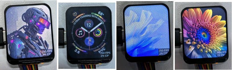
LVGL Arduino example
This example demonstrates the LVGL Widgets example. The frame rate can reach 20~30 frames in dynamic state
Effect demonstration
Usage of LVGL Components When developing using the LVGL framework, you can call the components according to the component instructions provided by the LVGL official documentation LVGL8.3 Documents
Below is a practical component investigation case for the LVGL library in the Arduino IDE
ESP-IDF
Introduction to ESP-IDF and Environment Setup (VSCode)
ESP-IDF(Espressif IoT Development Framework) is an open source IoT development framework launched by Espressif, specifically used for the development of its ESP32 series chips. ESP-IDF provides the necessary tools and libraries to build IoT applications, including Wi-Fi, Bluetooth, peripheral drivers, file systems, network protocol stacks, encryption, security and real-time operating system (FreeRTOS), etc.
The following description only applies to building using VSCode + ESP-IDF environment
- PS:
- If you want to use the Eclipse editor as the main development environment, please click the link to download Espressif-IDE to install and replace the ESP-IDF version ≥ v5.3.1
- If errors and exceptions such as TSL Error and Network Error occur during the installation of ESP-IDF as described below, please clean the directory folders again, ensure that the network environment is stable and free of agent contamination, etc., and reinstall. It takes a long time, please be patient.
Prerequisites
- If you are using Mac or Linux, please install the following ESP-IDF prerequisites. If you are using Windows, ignore this step.
Install VSCode
- Open the download page on the VSCode official website, select the corresponding system and system bits to download
- After running the installation package, the rest can be installed by default. However, for the sake of subsequent experience, it is recommended to check items 1, 2, and 3 in the box here.
- When the first and second items are turned on, you can open VSCode directly by right-clicking the file or directory, which can improve the subsequent use experience.
- When the third item is turned on, and when selecting the opening method, you can directly select VSCode
Install ESP-IDF plug-in
- Open VSCode, click on the plug-in manager, and search for ESP-IDF' to download and install, as shown in the figure:
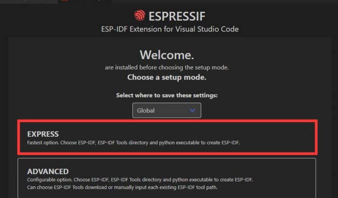
- After installation, the Espressif logo on the left toolbar is the plug-in. Click to enter the plug-in (there will be a short period of time to load the program), select EXPRESS Perform quick installation, as shown in the figure:
Install the ESP-IDF development environment
- Enter the EXPRESS installation interface, confirm that the ESP-IDF version ≥ v5.3.1 release version, the ESP-IDF directory and the ESP-IDF tool directory, click Install and wait patiently for the installation steps. Completed, as shown in the figure:
- If you are a user in China, you can choose the download server as Espressif. The installation process is relatively slow. Make sure the network is in good condition and wait patiently for the installation to complete.
- Installation process display:
- Installation complete flag:
Introduction to basic structure of ESP-IDF project
- Open the ESP-IDF plug-in, click New project, select the ESP-IDF sample-->sample_project-->Click Create
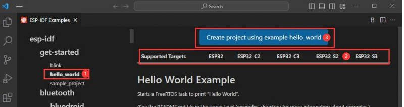
- Create a new one and open it in the window. You can see the structure of VSCode as follows:
├── CMakeLists.txt
├── main
│   ├── CMakeLists.txt
│   └── main.c
└── README.md
ESP-IDF Project details
- Component: The components in ESP-IDF are the basic modules for building applications. Each component is usually a relatively independent code library or library that can implement specific functions or services and can be reused by applications or other components. Similar to the definition of libraries in Python development.
- Component reference: In the Python development environment, importing a library only needs to import library name or path, while ESP-IDF is based on C language, and the importing a library is configured and defined through
the CMakeLists.txt. - The role of CmakeLists.txt: When compiling ESP-IDF, the compilation tool
CMakewill first read the build rules by reading the contents of the top-levelCMakeLists.txtof the project directory and identify the content that needs to be compiled. After the required components and programs are imported inCMakeLists.txt, the compilation toolCMakewill import each item that needs to be compiled according to the index. The compilation process is as follows:
- Component reference: In the Python development environment, importing a library only needs to import library name or path, while ESP-IDF is based on C language, and the importing a library is configured and defined through
Description of toolbar at the bottom of VSCode UI
When we open an ESP-IDF project, the environment will be automatically loaded at the bottom. For the development of ESP32-P4-Nano, the bottom toolbar is also very important, as shown in the figure:

- menuconfig, click to modify the content of the sdkconfig configuration file
- fullclean clean button, when the project compilation error or other operations pollute the compiled content, click to clean all the compiled content
- Compile
- Build project, when a project satisfies the build, compile through this button
- flash flashing button, when a project Build is passed, select the corresponding development board COM port, click this button to flash the compiled firmware to the chip
- monitor turns on the flashing port monitoring. When a project Build-->Flash, you can click this button to view the log output by the flashing and debugging ports to observe whether the application is working normally
- Build Flash Monitor one-click button, used to continuously execute Build-->Flash-->Monitor, often called "little flame"
Example description
esp-idf-st7789 example
In this example, the ST7789 is driven by SPI to display functions such as text, images, and drawing
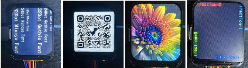
LVGL_Image example
This example shows the LVGLdemo and uses LVGL to display image data
Effect demonstration
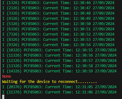
pcf85063 example
In this example, the PCF85063 is driven in a simple way to perform the time storage and read function
Effect demonstration
qmi8658 example
This example demonstrates how to use ESP-IDF to migrate a SensorLib and obtain gyroscope data from the qmi8658 driver of the migrated SensorLib
Effect demonstration
Resources
Schematic Diagrams
3D Diagrams
Demo
Datasheets
ESP32-S3
Other Components
Software Tools
Arduino
VScode
Other Resource Links
- ESP32-Arduino official documentation
- ESP32-Arduino official resources
- ESP-IDF official resources
- LVGL official documentation
FAQ
Question: 1. The board is too hot, what's the cause? How to solve it?
1. When you find the board is hot, please make sure to pull down the GPIO33 first, and pull down the buzzer pin, otherwise the passive buzzer is like a resistor that consumes power all the time, which leads to the LDO current pressure is very hot.
2. If you also use WiFi/Bluetooth function, hot is unavoidable, ESP32-S3 open wireless function related to power consumption will increase, resulting in heat.
3. It is not recommended to turn on the PSRAM function, if it is turned on, in the ESP-IDF and other scenarios may not pull down the GPIO33 or affect the display, at this time, we recommend removing the buzzer resistor to disconnect its function.
4. In the Arduino IDE environment, turn on the PSRAM, use external Flash, pull down the GPIO33, it will still cause a lot of heat, it is recommended to use a low-power program to play!
Question: 2. Why does the flashing fail?
1. When the serial port is occupied, programming will fail. Close the serial port monitor and re-program. 2. When the ESP32 program crashes, the flashing will fail. At this time, the development module needs to be completely powered off, hold down BOOT and then power on to enter the strong download mode before flashing. After flashing, it will not automatically exit the download mode, so you need to power off and restart again.
Question: 3. How to check the COM port you are using?
Windows: (1) View through Device Manager: Press the Windows + R keys to open the Run dialog box; type devmgmt.msc and press enter to open Device Manager; expand the Ports (COM and LPT) section, which will list all COM ports and their current status. (2) Use Command Prompt to view: Open Command Prompt (CMD); Enter the mode command, which will display status information for all COM ports. (3) Check the hardware connection: If you have connected an external device to the COM port, usually the device will occupy a port number, and you can determine which port is used by looking at the connected hardware. Linux: (1) Use the dmesg command to view: Open the terminal. (2) Use the ls command to view: Enter ls /dev/ttyS* or ls /dev/ttyUSB* to list all serial devices. (3) Use setserial command to view: Enter setserial -g /dev/ttyS* to view the configuration information of all serial devices.
Question: 4. How do I port the provided lib libraries? Or how to develop my own LCD screen? How to drive?
The LCD screen display chip used in this product is ST7789V2, and the touch chip is CST816T, there are drivers for the two chips in the libs we provided, for the display driver, please refer to TFT_eSPI enable, and for the touch driver, please refer to the Arduino_LVGL sample demo.
Question: 5. Can you help me with the code? Can you help me change the code?
This product is a development board and is not an end product. The product ecology is ESP32 core, and the ecology is very mature, the development environment is also very friendly, we do not assist in modifying the code, so creators, and geeks can play with their own DIY ability, if you have any questions you can ask the development engineers to answer for you.
If you think our products are good, and hope to batch customized hardware, customized shell, customized software, etc., welcome to contact the development engineers!
Support
Monday-Friday (9:30-6:30) Saturday (9:30-5:30)
Mobile: +86 13434470212
Email: services01@spotpear.com
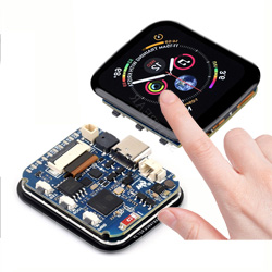
ESP32-S3 1.69inch Touchscreen LCD Round Display WiFi Bluetooth With QST Attitude Gyro Sensor QMI8658
[Tutorial Navigation]
- Overview
- LCD Description
- Sample Demo
- Arduino IDE
- ESP-IDF
- Resources
- FAQ
- Question: 1. The board is too hot, what's the cause? How to solve it?
- Question: 2. Why does the flashing fail?
- Question: 3. How to check the COM port you are using?
- Question: 4. How do I port the provided lib libraries? Or how to develop my own LCD screen? How to drive?
- Question: 5. Can you help me with the code? Can you help me change the code?
- Support