


- sales/support
Google Chat:---
- sales
+86-0755-88291180
- sales01
sales@spotpear.com
- sales02
dragon_manager@163.com
- support
tech-support@spotpear.com
- CEO-Complaints
zhoujie@spotpear.com
- Only Tech-Support
WhatsApp:13246739196
- Purchase/Shipping/Refund
WhatsApp:13424403025
- HOME
- >
- ARTICLES
- >
- Common Moudle
- >
- ESP
ESP32-S3-Touch-LCD-4 User Guide
Overview
Introduction
ESP32-S3-Touch-LCD-4 is a low-cost, high-performance MCU board designed by Waveshare. It supports 2.4GHz WiFi and BLE 5, integrates high-capacity Flash and PSRAM, and has a 4-inch capacitive touch LCD screen on board to smoothly run GUI interface programs such as LVGL. Combine a variety of peripheral interfaces (e.g., CAN, I2C, RS485, etc.) to quickly develop applications such as HMIs for ESP32-S3. With a wide range of functions and interfaces, it can meet power consumption requirements in Internet of Things (IoT), mobile devices, smart home and other applications.
Features
- Equipped with high-performance Xtensa 32-bit LX7 dual-core processor, up to 240MHz main frequency
- Supports 2.4GHz Wi-Fi (802.11 b/g/n) and Bluetooth 5 (BLE), with onboard antenna
- Built-in 512KB SRAM and 384KB ROM, with onboard 16MB Flash and 8MB PSRAM
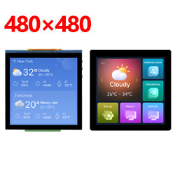
- Onboard 4inch capacitive touch screen with 480 × 480 resolution, 65K color
- Supports I2C interface control for capacitive touch, with 5-point touch, and supports interrupts
- Onboard CAN, RS485, I2C interface and TF card slot, integrates full-speed USB
- Onboard RTC,lithium battery recharge/discharge IC, suitable for mobile scenarios
- Supports flexible clock, module power supply independent setting and other controls to realize low power consumption in different scenarios
Onboard Resources
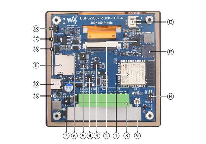
1. ESP32-S3N16R8 module 2. SW6106 battery charge and discharge chip 3. TJA1051T/3/1J 4. SP3485 chip 5. PCF85063 6. TCA9554PWR 7. XL1509-ADJE1 power chip 8. 3.5mm 10pin terminal socket 9. RTC battery header |
11. Micro SD card slot 12. PH2.0 Lithium battery interface 13. Buzzer 14. CAN and RS485 terminal resistor switch 15. Power indicator 16. BOOT button 17. RESET button 18. PWRKEY power on/off button |
Interfaces
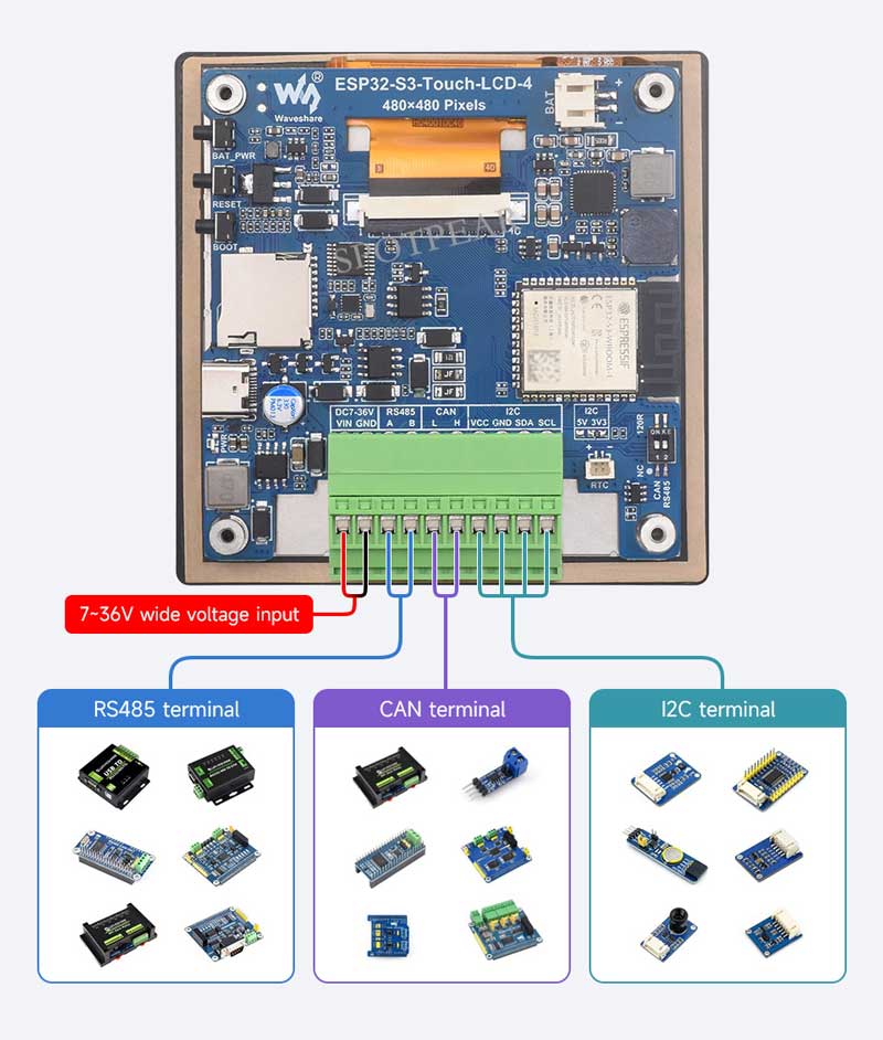
- CAN interface: Implements the transmission and reception control, data analysis, acquisition and monitoring of the CAN bus network
- PH2.0 battery interface: The development board uses a high-efficiency charge/discharge management chip SW6106, which supports I2C to read the battery level
- RS485 interface: The development board is equipped with an RS485 interface circuit, allowing direct connection to RS485 device for communication, with automatic switching between transmit and receive modes of the RS485 circuit
- I2C interface: ESP32-S3 provides multi-channel hardware I2C, currently using GPIO8 (SDA1) and GPIO9 (SCL1) pins for I2C bus to mount the IO expansion chip
GPIO7 (SCL0), GPIO15 (SDA0) pins are used as touch interface, I2C interface
| ESP32-S3-WROOM-x | LCD | USB | SD | UART | CAN | RTC | OTS |
| GPIO0 | CANRX | ||||||
| GPIO1 | LCD_SDA | MOSI | |||||
| GPIO2 | LCD_SCL | SCK | |||||
| GPIO3 | R2 | ||||||
| GPIO4 | MISO | ||||||
| GPIO5 | B1 | ||||||
| GPIO6 | CANTX | ||||||
| GPIO7 | TP_SCL | RTC_SCL | SCL | ||||
| GPIO8 | R3 | Expander_SDA | |||||
| GPIO9 | G5 | Expander_SCL | |||||
| GPIO10 | G4 | ||||||
| GPIO11 | G3 | ||||||
| GPIO12 | G2 | ||||||
| GPIO13 | G1 | ||||||
| GPIO14 | G0 | ||||||
| GPIO15 | TP_SDA | RTC_SDA | SDA | ||||
| GPIO16 | TP_INT | ||||||
| GPIO17 | R5 | ||||||
| GPIO18 | R4 | ||||||
| GPIO19 | USB_DN | ||||||
| GPIO20 | USB_DP | ||||||
| GPIO21 | B5 | ||||||
| GPIO38 | HSYNC | ||||||
| GPIO39 | VSYNC | ||||||
| GPIO40 | DE | ||||||
| GPIO41 | LCD_PCLK | ||||||
| GPIO42 | LCD_CS | ||||||
| GPIO43 | RS485_RX | ||||||
| GPIO44 | RS485_TX | ||||||
| GPIO45 | B2 | ||||||
| GPIO46 | R1 | ||||||
| GPIO47 | B4 | ||||||
| GPIO48 | B3 | ||||||
| TCA9554PWR | - | - | - | - | - | - | - |
| EXIO0 | TP_RST | ||||||
| EXIO1 | BL_EN | ||||||
| EXIO2 | LCD_RST | ||||||
| EXIO3 | SD_CS | ||||||
| EXIO4 | BLC | ||||||
| EXIO5 | BEE_EN | ||||||
| EXIO6 | RTC_INT | ||||||
| EXIO7 | DO1 |
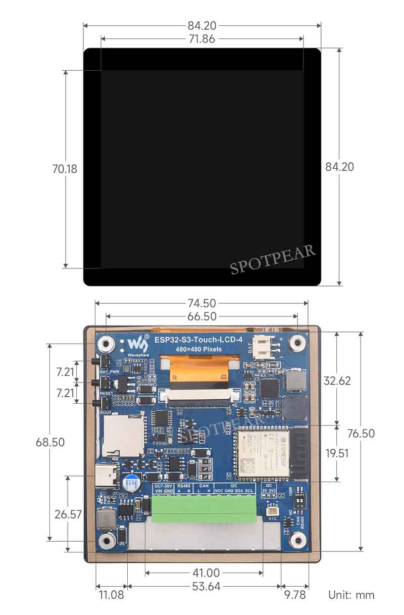
Dimensions
I2C
- Two way I2C
- ESP32-S3 supports two I2C channels to work at the same time, this development board uses two I2C drivers, SDA0 (IO8) and SCL0 (IO9), for I2C 0 to drive expansion chip TCA9554PWR
- SDA1(IO15) and SCL1(IO7) for I2C 1 to drive other I2C slave devices
- In the new version, I2C0 and I2C1 share I2C1 single-channel I2C (the demo is compatible)
Other instructions
- Currently, under ESP-IDF v5.3, the average frame rate limit for running the LVGL benchmark demo with a single core is 26 frames per second, corresponding to an interface frame rate of 41 (PCLK 21 MHz). Before compilation, ESP32 and LVGL need to be configured through menuconfig:
CONFIG_FREERTOS_HZ=1000
CONFIG_ESP_DEFAULT_CPU_FREQ_MHZ_240=y
CONFIG_ESPTOOLPY_FLASHMODE_QIO=y
CONFIG_ESPTOOLPY_FLASHFREQ_120M=y [Need to be consistent with PSRAM]
CONFIG_SPIRAM_MODE_OCT=y
CONFIG_IDF_EXPERIMENTAL_FEATURES=y and CONFIG_SPIRAM_SPEED_120M=y [Need to be consistent with FLASH]
CONFIG_SPIRAM_FETCH_INSTRUCTIONS=y
CONFIG_SPIRAM_RODATA=y
CONFIG_ESP32S3_DATA_CACHE_LINE_64B=y
CONFIG_COMPILER_OPTIMIZATION_PERF=y
#The following LVGL configuration items are helpful for frame rate improvement (LVGL v8.3):
#define LV_MEM_CUSTOM 1 or CONFIG_LV_MEM_CUSTOM=y
#define LV_MEMCPY_MEMSET_STD 1 or CONFIG_LV_MEMCPY_MEMSET_STD=y
#define LV_ATTRIBUTE_FAST_MEM IRAM_ATTR or CONFIG_LV_ATTRIBUTE_FAST_MEM=y
Usage instructions
ESP32-S3-Touch-LCD-4 currently provides two development tools and frameworks, Arduino IDE and ESP-IDF, providing flexible development options, you can choose the right development tool according to your project needs and personal habits.
Development tools
Arduino IDEArduino IDE is an open source electronic prototyping platform, convenient and flexible, easy to get started. After a simple learning, you can start to develop quickly. At the same time, Arduino has a large global user community, providing an abundance of open source code, project examples and tutorials, as well as rich library resources, encapsulating complex functions, allowing developers to quickly implement various functions. | |
ESP-IDFESP-IDF, or full name Espressif IDE, is a professional development framework introduced by Espressif Technology for the ESP series chips. It is developed using the C language, including a compiler, debugger, and flashing tools, etc., and can be developed via the command lines or through an integrated development environment (such as Visual Studio Code with the Espressif IDF plugin). The plugin offers features such as code navigation, project management, and debugging. |
Each of these two development approaches has its own advantages, and developers can choose according to their needs and skill levels. Arduino are suitable for beginners and non-professionals because they are easy to learn and quick to get started. ESP-IDF is a better choice for developers with a professional background or high performance requirements, as it provides more advanced development tools and greater control capabilities for the development of complex projects.
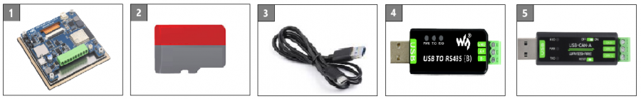
Components preparation
- ESP32-S3-Touch-LCD-4 x1
- TF card x 1
- USB cable (Type-A to Type-C) x 1
- USB TO RS485 Bidirectional Converter x1
- USB to CAN adapter analyzer x1
Working with Arduino
This chapter introduces setting up the Arduino environment, including the Arduino IDE, management of ESP32 boards, installation of related libraries, program compilation and downloading, as well as testing demos. It aims to help users master the development board and facilitate secondary development. 
Environment setup
Download and install Arduino IDE
- Click to visit the official website, select the corresponding system and system bit to download.
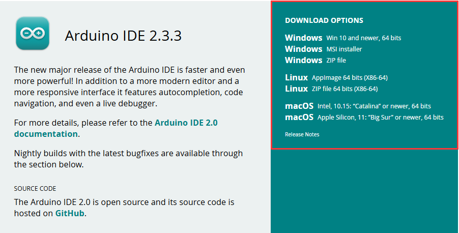
- Run the installer and install all by default.
Install Arduino-ESP32
- Regarding ESP32-related motherboards used with the Arduino IDE, the esp32 by Espressif Systems library must be installed first.
- It is generally recommended to use Install Online. If online installation fails, use Install Offline.
- To install the Arduino-ESP32 tutorial, please refer to Arduino board manager tutorial
| Board name | Board installation requirements | Version number requirements |
|---|---|---|
| ESP32-S3-Touch-LCD-4 | "Install Offline" / "Install Online" | 3.0.7 |
Install library
- When installing Arduino libraries, there are usually two ways to choose from: Install online and Install offline. If the library installation requires offline installation, you must use the provided library file
For most libraries, users can easily search and install them through the online library manager of the Arduino software. However, some open-source libraries or custom libraries are not synchronized to the Arduino Library Manager, so they cannot be acquired through online searches. In this case, users can only manually install these libraries offline. - For library installation tutorial, please refer to Arduino library manager tutorial
- ESP32-S3-Touch-LCD-4 library file is stored in the sample program, click here to jump: ESP32-S3-Touch-LCD-4 Demo
| Library Name | Description | Version | Library Installation Requirements |
|---|---|---|---|
| ESP32_Display_Panel | ST7701, GT911 driver library | v0.1.8 | "Install Online" or "Install Offline" |
| ESP32_IO_Expander | TCA9554 IO expansion chip driver library | v0.0.4 | "Install Offline" (return value of IOExpander_Library changed) |
| lvgl | LVGL graphical library | v8.4.0 | "Install Online" requires copying the demos folder to src after installation. "Install Offline" is recommended |
| lv_conf.h | LVGL configuration file | —— | "Install Offline" |
Run the First Arduino Demo
New Project
- Run the Arduino IDE and select
File->New Sketch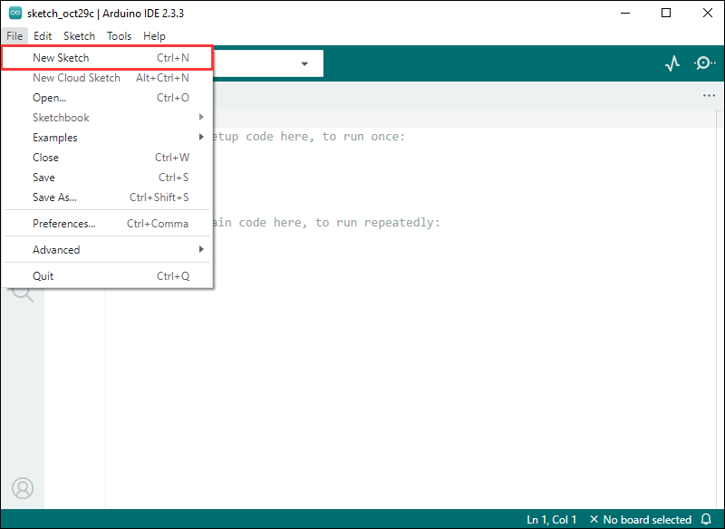
- Enter the code:
void setup() {
  // put your setup code here, to run once:
  Serial.begin(115200);
}

void loop() {
  // put your main code here, to run repeatedly:
  Serial.println("Hello, World!");
  delay(2000);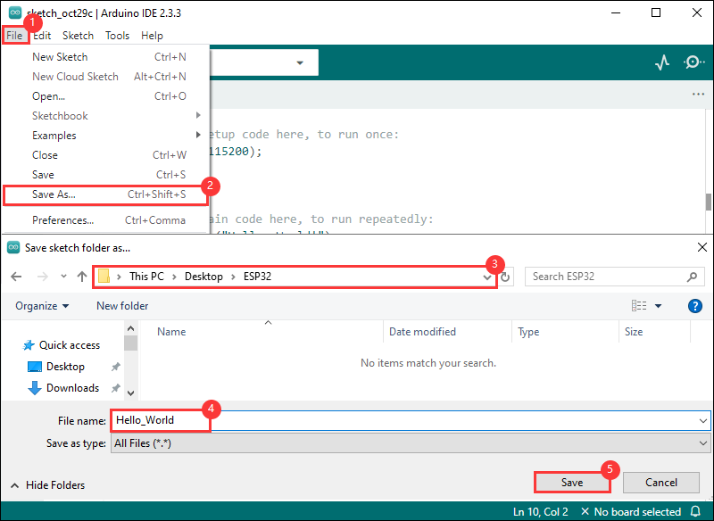
}- Save the project and select
File->Save As.... In the pop-up menu, select the path to save the project, and enter a project name, such as Hello_World, clickSave
Compile and Flash Demos
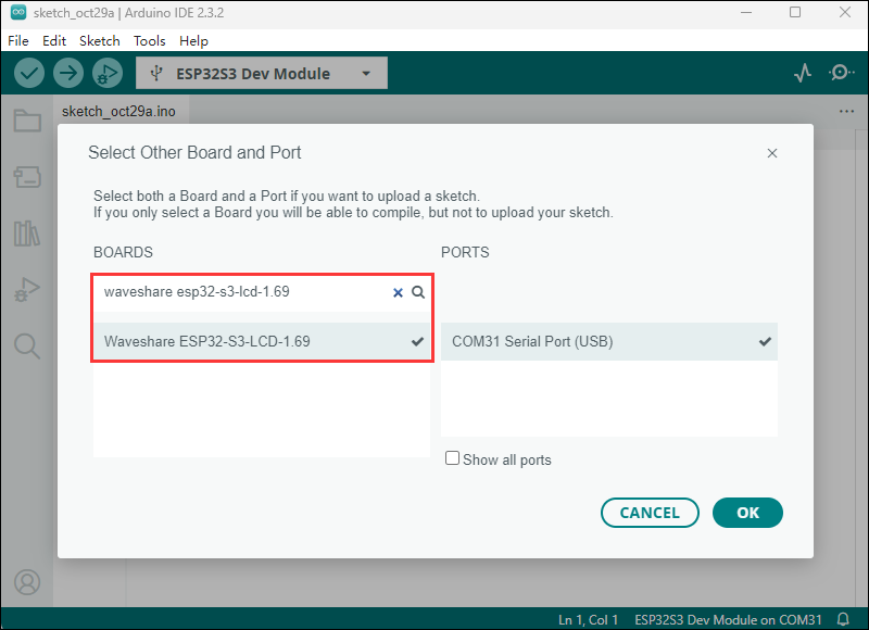
- Select the corresponding development board, take the ESP32S3 motherboard as an example:
①. Click to select the dropdown menu option Select Other Board and Port;
②. Search for the required development board model esp32s3 dev module and select;
③. Select COM Port;
④. Save the selection.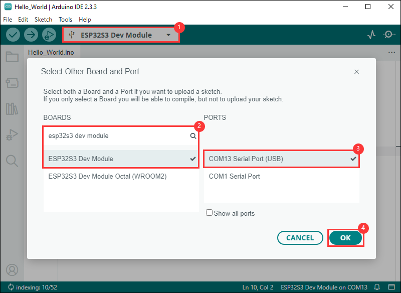
- Some development boards with specified version numbers support direct model selection, for example, "Waveshare ESP32-S3-LCD-1.69":
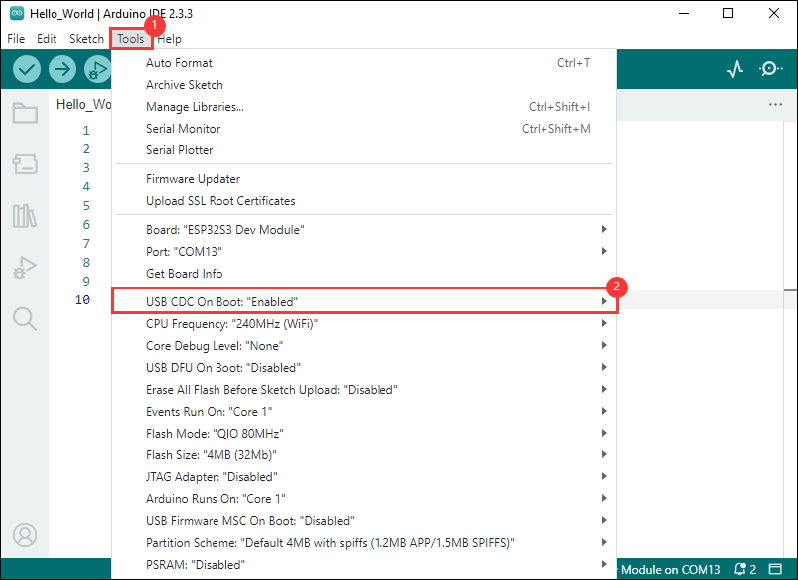
- If the ESP32S3 mainboard only has a USB port, you need to enable USB CDC, as shown in the following diagram:
- Compile and upload the program:
①. Compile the program; ②. Compile and download the program; ③. Download successful.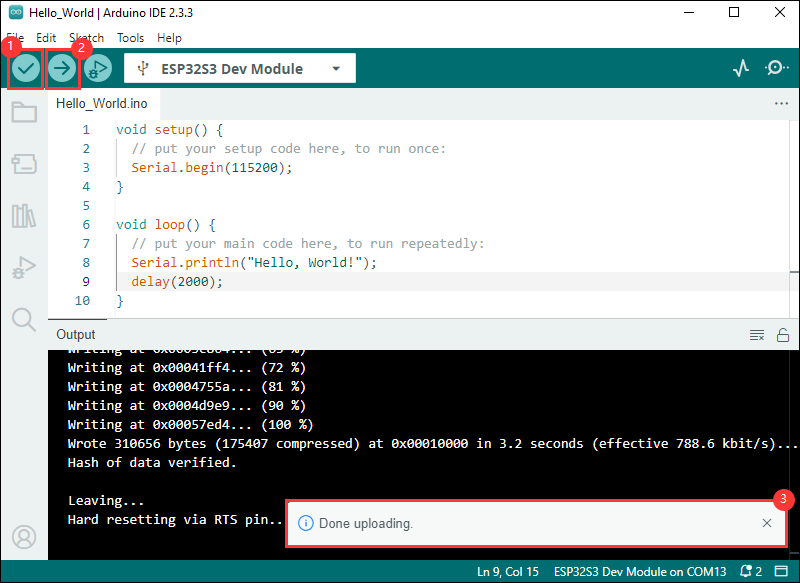
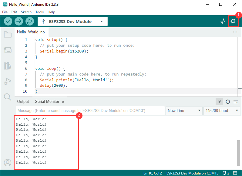
- Open the Serial Monitor window, and the demo will print "Hello World!" every 2 seconds, and the operation is as follows:
Demos

| Demo | Basic Description | Dependency Library |
|---|---|---|
| 01_PanelTest | Test the RGB screen | GFX_Library_for_Arduino |
| 02_LVGL_Porting | Test the RGB touch screen | GFX_Library_for_Arduino, Arduino DriveBus |
| 03_Rotation | Test RS-485 seat | GFX_Library_for_Arduino |
| 04_RS485_Test | Test RS-485 seat | GFX_Library_for_Arduino |
| 05_TWAIreceive | Test CAN seat | GFX_Library_for_Arduino |
| 06_TWAItransmit | Test CAN seat | SensorLib, GFX_Library_for_Arduino |
| 07_SD_Test | Test TF card slot | LVGL |
- ESP32-S3-Touch-LCD-4 supports direct model selection
- Take ESP32-S3-LCD-1.69 as an example

Arduino project parameter settings
- The sample program that requires the use of the screen needs to be configured as follows
PSRAMenabled, and some versions are set to OPI PSRAM

- After connecting to the computer, press BAT_PWR to turn it on. In the powered-on state, double-click BAT_PWR to turn it off
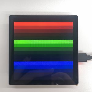
01_PanelTest
Hardware connection
- Connect the board to the computer using a USB cable

Code analysis
setup():- Initialize the serial port and print the start information;
- Create
ESP_Panelobject and initialize the panel; - Get pointers to the individual components of the panel (LCD, touch, backlight);
- Based on the existence of the component, perform corresponding operations such as turning off and on the backlight, setting the LCD's refresh completion callback function, and conducting a color bar test.
loop():- If a touch component exists, read the touch point information;
- Based on the reading results, different treatments are performed. The touch point information is printed if it succeeds, and the error message is printed if it fails;
- If touch interrupt is not enabled, delay for a period of time to avoid frequent reading;
- If the touch component does not exist, delay 1000 milliseconds and print "IDLE loop".
Result demonstration
- After flashing the code, you can observe stripes of blue, green, and red on the screen (If there's no screen response after flashing the code, check whether the correct configurations are set in Arduino IDE -> Tools: Enable PSRAM (8MB OPI))
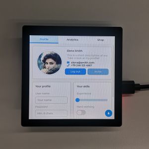
02_LVGL_Porting
Hardware connection
- Connect the board to the computer using a USB cable
Code analysis
setup():- Extender Initialization:
- Create an extender object with specific parameters, initialize and attempt to start the extender. If initialization fails, try again with the alternate parameters. If successful, the success message is output through the serial port
- Serial port and pin settings:
- Set pin 16 as output and initialize it to low level, initialize the serial port and set the baud rate to 115200, print the title and "start" information
- Panel device initialization:
- Create
ESP_Panelobject and initialize the panel, start the panel device, if the anti-tearing function is enabled, set the RGB bus parameters according to the LVGL configuration
- Create
- LVGL initialization and user interface creation:
- Initialize LVGL, pass in the LCD and touch objects of the panel, print information, and lock the LVGL mutual exclusion lock (since the LVGL API is not thread-safe); create a simple label and set the text as the title, display it centered on the screen, call a function to demonstrate LVGL widget examples, and unlock the mutual exclusion lock
- Extender Initialization:
Result demonstration
- After flashing the code, a series of touch screen operations can be performed, which is a demo for LVGL porting by users (If there's no screen response after flashing the code, check whether the correct configurations are set in Arduino IDE -> Tools: Enable PSRAM (8MB OPI))
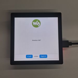
03_Rotation
Hardware connection
- Connect the board to the computer using a USB cable
Code analysis
setup():- Responsible for initializing the IO expander, configuring hardware and serial communication, initializing the panel device and LVGL, and creating the user interface, which is the initialization entry point for the entire program
rotateDisplay():
This function is used to rotate the display interface. It receives a pointer of type lv_disp_t and a rotation angle parameter
- Lock the mutual exclusion lock of LVGL to ensure thread safety when modifying display settings
- Use the
lv_disp_set_rotationfunction to set the rotation angle of the LVGL display - Use the
lv_label_set_text_fmtfunction to update the label text that displays the rotation angle to show the current rotation angle - Unlock mutual exclusion lock, allowing other parts of the program to continue accessing the LVGL API
onRightBtnClickCallback():- The click callback function of the button, which is used to respond to the user click operation on the left and right buttons to achieve rotation control of the display
- When the right button is clicked, this function checks the current rotation state. If the current rotation angle is
LV_DISP_ROT_270, then set the rotation angle toLV_DISP_ROT_NONE(no rotation); otherwise, increase the rotation angle by one unit - Call the
rotateDisplayfunction to actually perform the display rotation operation
onLeftBtnClickCallback():- When the left button is clicked, this function also checks the current rotation state. If the current rotation angle is
LV_DISP_ROT_NONE, then set the rotation angle toLV_DISP_ROT_270(no rotation); otherwise, decrease the rotation angle by one unit - Call the
rotateDisplayfunction to actually perform the display rotation operation
- When the left button is clicked, this function also checks the current rotation state. If the current rotation angle is
Result demonstration
04_RS485_Test
Hardware connection
- Connect the board to the computer using a USB cable
- Connect the development board to USB to RS485 converter, as shown in the figure

Code analysis
setup():Serial2.begin(115200, SERIAL_8N1, 43, 44);: Initialize UART2, set the baud rate to 115200, set the data format to 8-bit data, no parity bit, 1 stop bit, and specify GPIO43 (RXD) and GPIO44 (TXD) as the transmit and receive pins
loop():- Check if UART2 has data to read using
Serial2.available(), read data usingSerial2.read(), and when certain conditions are met, send the data from the buffer usingSerial2.println(buffer)to realize the reception and transmission of UART2 data
- Check if UART2 has data to read using
Result demonstration
- Open the serial port debugging assistant to send a message to the ESP32-S3-Touch-LCD-4 device, and the device will return the received message to the serial port debugging assistant

05_TWAIreceive
Hardware connection
- Connect the board to the computer using a USB cable
- Connect the development board to USB-CAN-A, as shown in the figure

Code analysis
- Function overview:
- Initialize serial communication to output information
- Configure the GPIO pin as the output
- Install and start the CAN (Controller Area Network) bus driver (TWAI), connect to the specified RX_PIN (0) and TX_PIN (6) pins, and set it to monitor mode
- In the main loop, if a CAN driver is installed, check if there are any alarms triggered, handle various alarm conditions such as error passive state, bus errors, and full receive queues. If there is a data alert reception, process the received CAN messages
- Important interface and pin descriptions:
- RX_PIN(0) and TX_PIN(6): Pins for connecting to a CAN bus transceiver
- GPIO_OUTPUT_PIN_SEL (corresponding to GPIO15 and GPIO16): Used to configure specific GPIO pins as output mode
Result demonstration
- ESP32-S3-Touch-LCD-4 waits USB-CAN-A_TOOL to send a message. If the message is received successfully, it will be printed to the serial port.


06_TWAItransmit
Hardware connection
- Connect the board to the computer using a USB cable
- Connect the development board to USB-CAN-A, as shown in the figure
Code analysis
- Function overview:
- Initialize serial communication to output information
- Configure specific GPIO pins (RX_PIN and TX_PIN) as output mode
- Install and start the CAN (Controller Area Network) bus driver (TWAI), connect to the specified RX_PIN (0) and TX_PIN (6) pins, and set it to no-answer mode
- Reconfigure CAN alarms to detect specific statuses, including sending related alerts and bus error alerts
- In the main loop, if the CAN driver is installed, check if there are alarms triggered and handle various alarm situations, while sending CAN messages at regular intervals
- Important interface and pin descriptions:
- RX_PIN(0) and TX_PIN(6): Pins for connecting to a CAN bus transceiver
- GPIO_OUTPUT_PIN_SEL: Used to configure specific GPIO pins as output mode, here for RX_PIN and TX_PIN
Result demonstration
- Serial port print indicates successful CAN message transmission. After configuring USB-CAN-A_TOOL, you can observe the CAN messages sent by the ESP32-S3-Touch-LCD-4 upon startup.

- Observe USB-CAN-A_TOOL further, and you will see the CAN messages sent by ESP32-S3-Touch-LCD-4

07_SD_Test
Hardware connection
- Connect the development board to the computer using a USB cable
- Insert the TF card into the board

Code analysis
- TF card initialization and detection
- Initialize the TF card
- Initialize the TF card by setting specific pins (
SDMMC_CLK,SDMMC_CMD,SDMMC_DATA). If initialization fails, the program will enter an infinite loop, ensuring that no further operations are executed without successfully mounting the TF card
- Initialize the TF card by setting specific pins (
- Detect TF card type and size
- Detect the type of TF card (such as MMC, SDSC, SDHC, etc.) and print information, allowing the user to understand the specific specifications of the connected TF card. At the same time, get the size of the TF card and print it in MB, making it easy for users to know the storage capacity
- List the contents of the TF card directory
- y calling the
listDirfunction, list the files and directories under the root directory of the TF card, providing users with an intuitive understanding of the content stored on the TF card, making it convenient for subsequent file operations and management
- y calling the
- Initialize the TF card
Result demonstration
- The ESP32-S3-Touch-LCD-4 can identify the type and size of an TF card, and then perform file operations such as adding, deleting, modifying, and querying.

Working with ESP-IDF
This chapter introduces setting up the ESP-IDF environment setup, including the installation of Visual Studio and the Espressif IDF plugin, program compilation, downloading, and testing of example programs, to assist users in mastering the development board and facilitating secondary development.

Environment setup
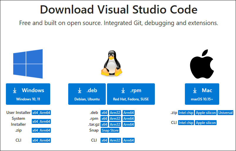
Download and install Visual Studio
- Open the download page of VScode official website, choose the corresponding system and system bit to download
- After running the installation package, the rest can be installed by default, but here for the subsequent experience, it is recommended to check boxes 1, 2 and 3
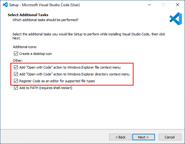
- After the first two items are enabled, you can open VSCode directly by right-clicking files or directories, which can improve the subsequent user experience.
- After the third item is enabled, you can select VSCode directly when you choose how to open it.
Install Espressif IDF Plugin
- It is generally recommended to use Install Online. If online installation fails due to network factor, use Install Offline.
- For more information about how to install the Espressif IDF plugin, see Install Espressif IDF Plugin
- Espressif IDF version ≥ v5.3.1
Run the First ESP-IDF Demo
New Project
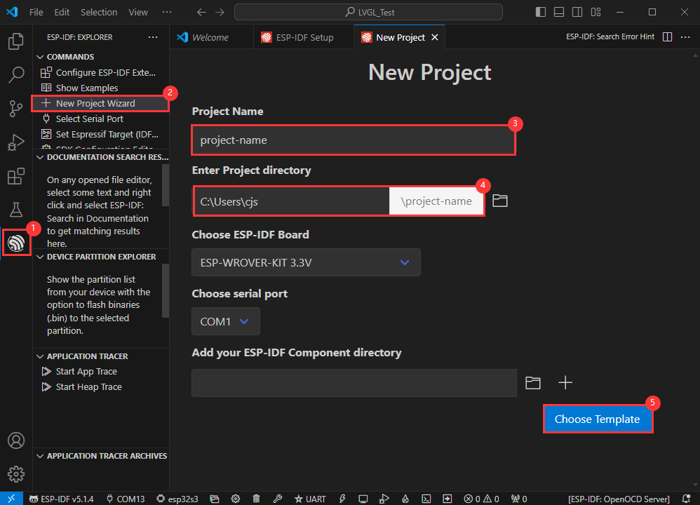

Create Demo
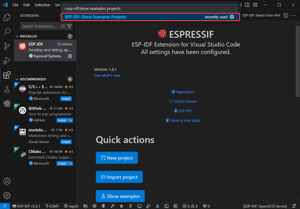
- Using the shortcut F1, enter esp-idf:show examples projects
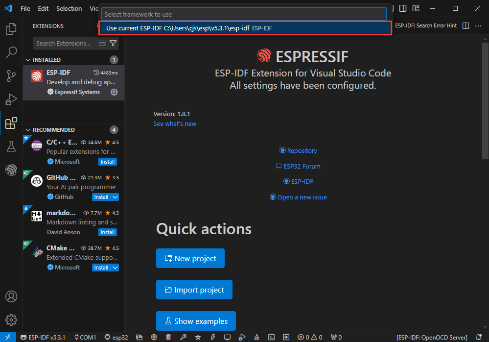
- Select your current IDF version
- Take the Hello world demo as an example
①Select the corresponding demo
②Its readme will state what chip the demo applies to (how to use the demo and the file structure are described below, omitted here)
③Click to create the demo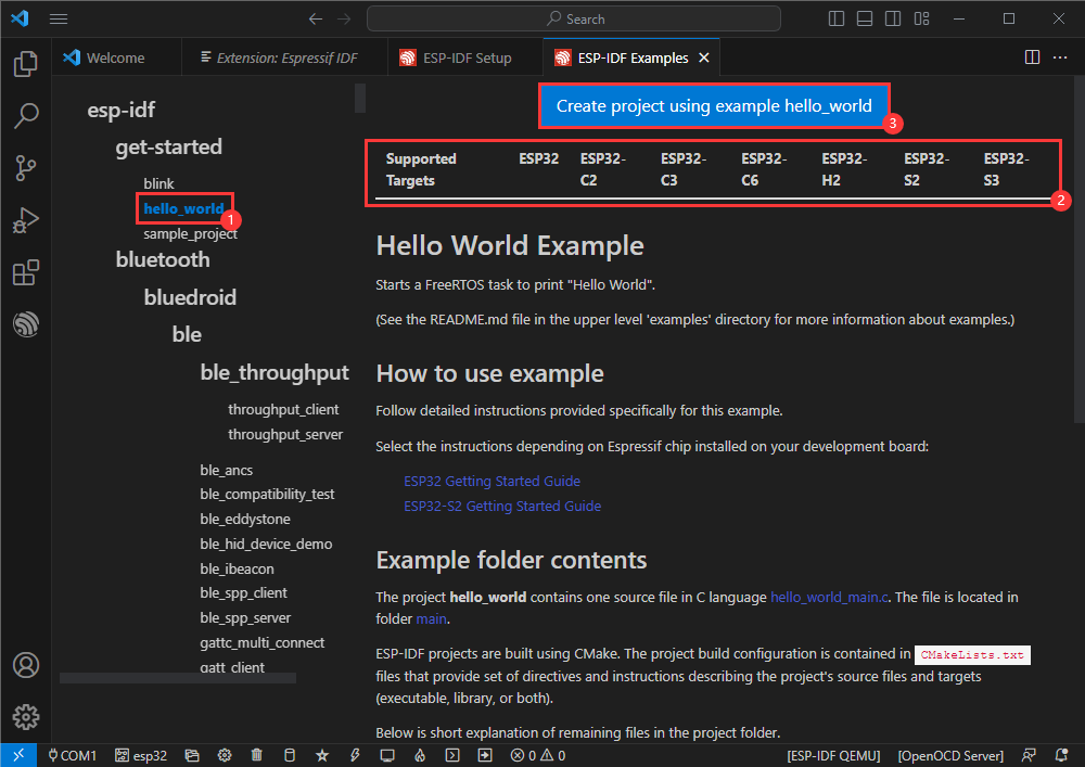
- Select the path to save the demo, and require that the demos cannot use folders with the same name

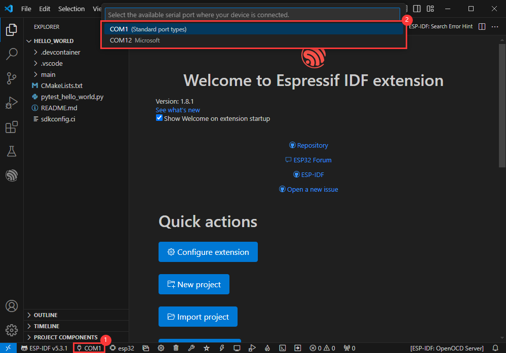
Modify COM Port
- The corresponding COM ports are shown here, click to modify them
- Please select the COM ports according to your device (You can view it from the device manager)
- In case of a download failure, please press the Reset button for more than 1 second or enter download mode, and wait for the PC to recognize the device again before downloading once more
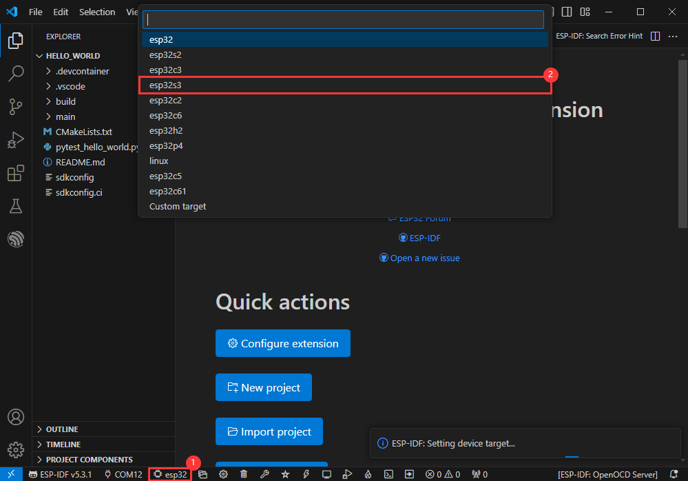
Modify Driver Object
- Select the object we need to drive, which is our main chip ESP32S3
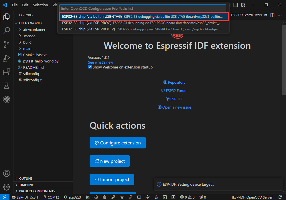
- Choose the path to openocd, it doesn't affect us here, so let's just choose one
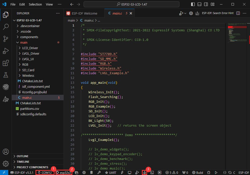
Other Status Bar Functions
①.ESP-IDF Development Environment Version Manager, when our project requires differentiation of development environment versions, it can be managed by installing different versions of ESP-IDF. When the project uses a specific version, it can be switched to by utilizing it
②.Device flashing COM port, select to flash the compiled program into the chip
③.Select set-target chip model, select the corresponding chip model, for example, ESP32-P4-NANO needs to choose esp32p4 as the target chip
④.menuconfig, click it to Modify sdkconfig configuration file Project configuration details
⑤.fullclean button, when the project compilation error or other operations pollute the compiled content, you can clean up all the compiled content by clicking it
⑥.Build project, when a project satisfies the build, click this button to compile
⑦.Current download mode, the default is UART
⑧.flash button, when a project build is completed, select the COM port of the corresponding development board, and click this button to flash the compiled firmware to the chip
⑨.monitor enable flashing port monitoring, when a project passes through Build --> Flash, click this button to view the log of output from flashing port and debugging port, so as to observe whether the application works normally
⑩.Debug
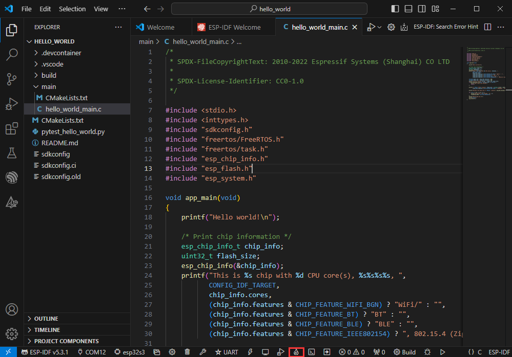
⑪.Build Flash Monitor one-click button, which is used to continuously execute Build --> Flash --> Monitor, often referred to as "little flame"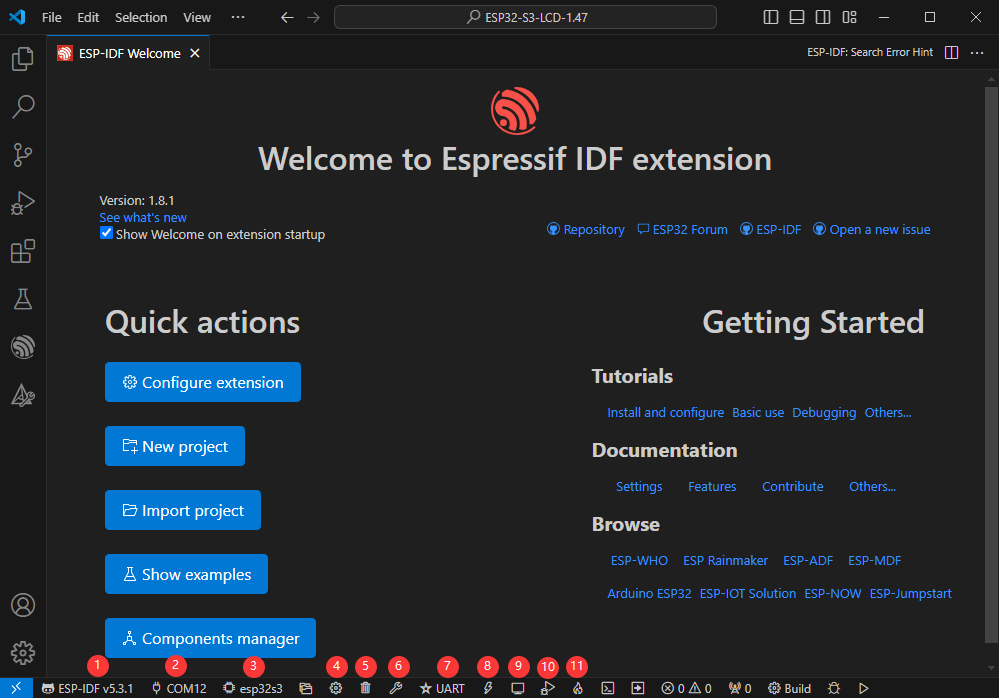
Compile, Flash and Serial Port Monitor
- Click on the all-in-one button we described before to compile, flash and open the serial port monitor
- It may take a long time to compile especially for the first time
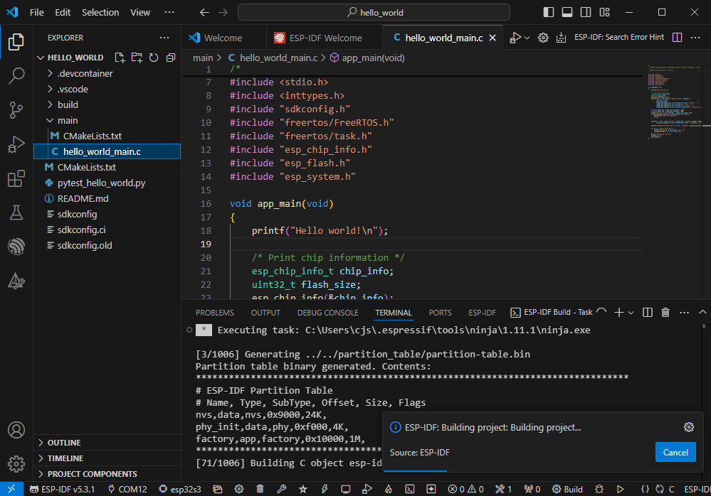
- During this process, the ESP-IDF may take up a lot of CPU resources, so it may cause the system to lag
- If it is the first time to flash the program for a new project, you will need to select the download method, and select UART
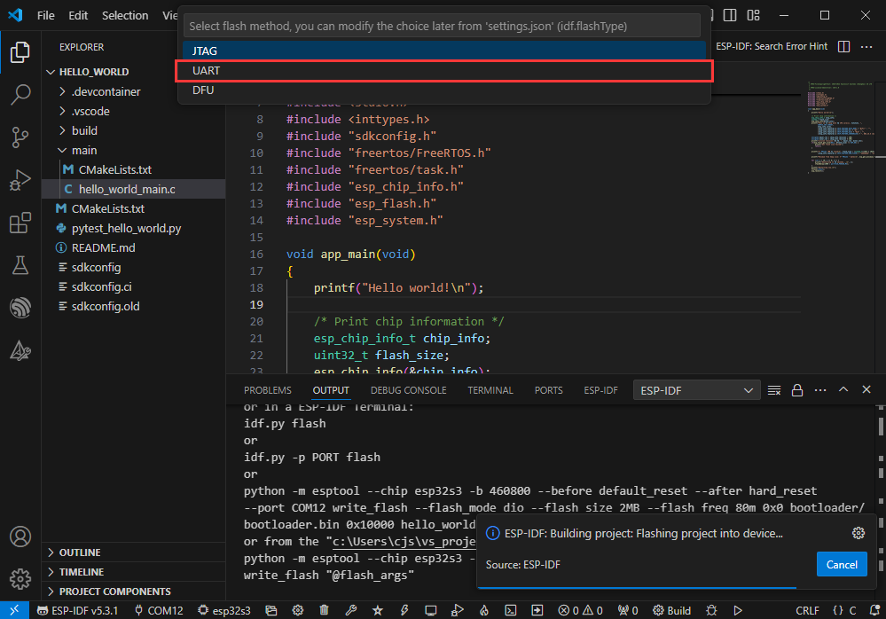
- This can also be changed later in the Download methods section (click on it to pop up the options)

- As it comes with the onboard automatic download circuit, it can be downloaded automatically without manual operation
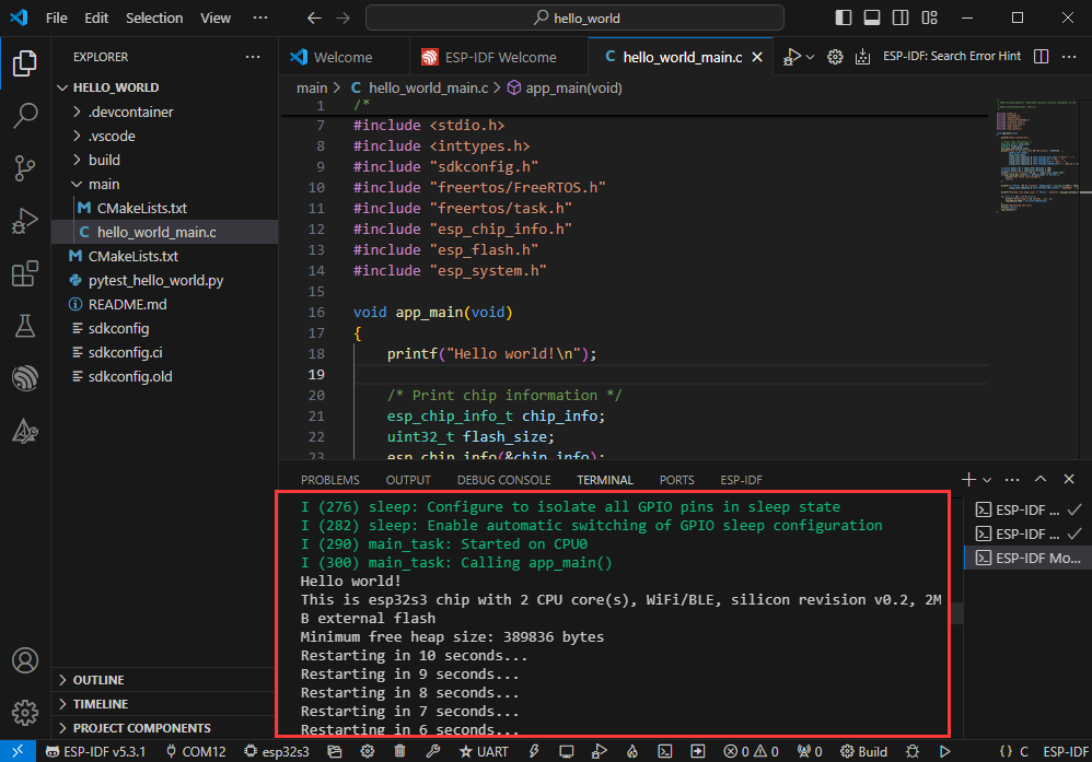
- After successful download, it will automatically enter the serial monitor, you can see the chip output the corresponding information and be prompted to restart after 10S
Use the IDF Demos
Open In the Software
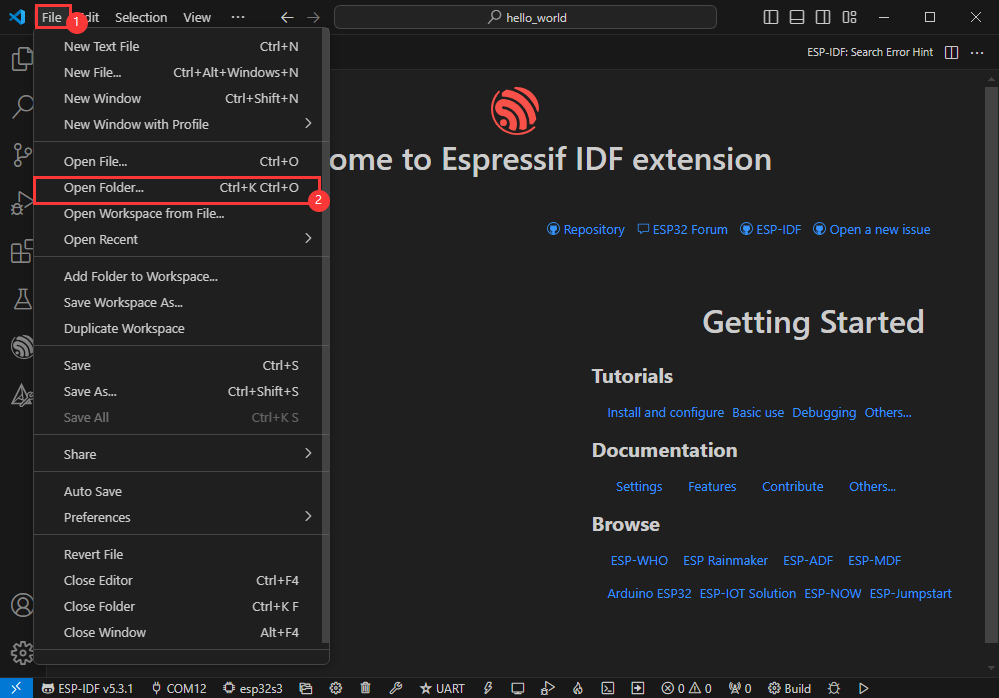
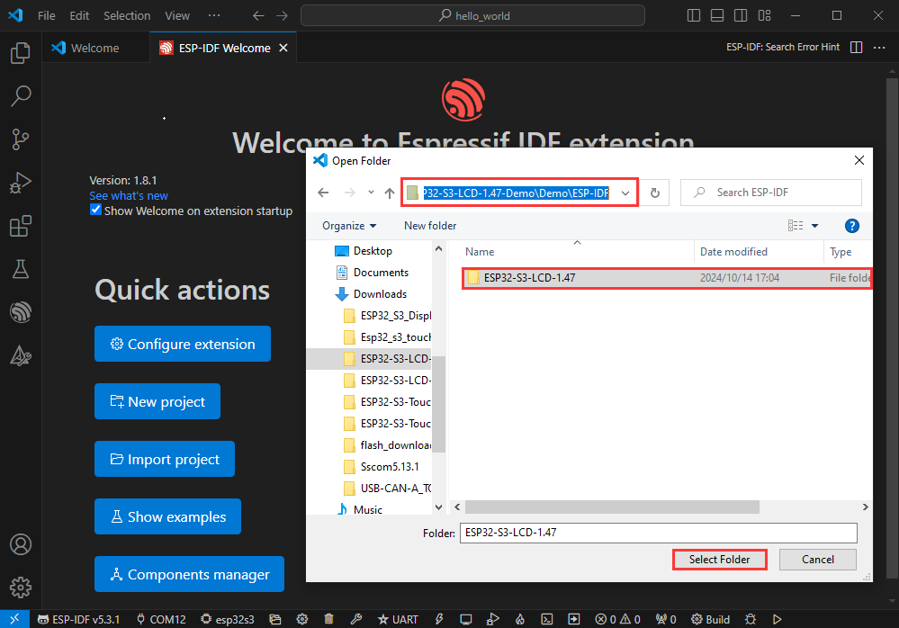
- Open VScode software and select the folder to open the demo
- Select the provided ESP-IDF example and click to select the file (located in the /Demo/ESP-IDF path under demo)
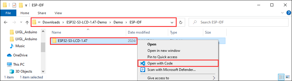
Open from Outside the Software
- Select the project directory correctly and open the project, otherwise it will affect the compilation and flashing of subsequent programs
- After connecting the device, select the COM port and model, click below to compile and flash to achieve program control
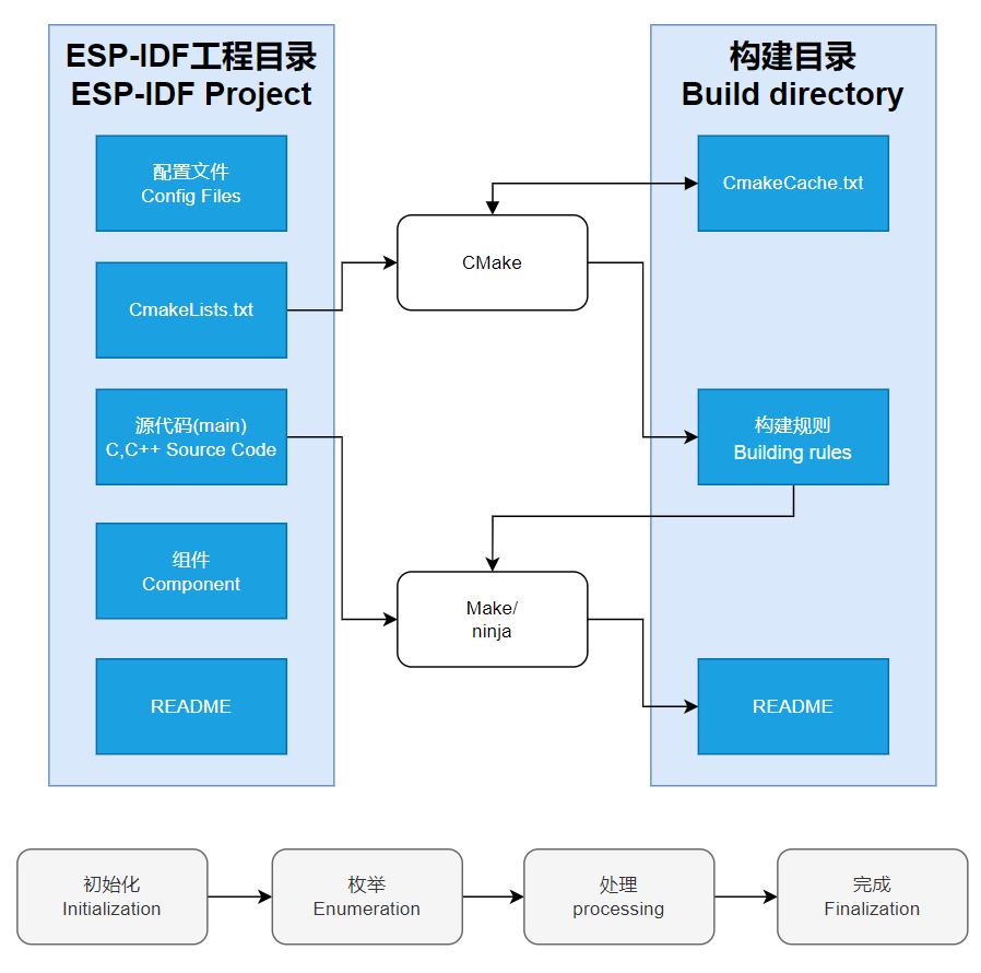
ESP-IDF Project Details
- Component: The components in ESP-IDF are the basic modules for building applications, each component is usually a relatively independent code base or library, which can implement specific functions or services, and can be reused by applications or other components, similar to the definition of libraries in Python development.
- Component reference: The import of libraries in the Python development environment only requires to "import library name or path", while ESP-IDF is based on the C language, and the importing of libraries is configured and defined through
CMakeLists.txt. - The purpose of CmakeLists.txt: When compiling ESP-IDF, the build tool
CMakefirst reads the content of the top-levelCMakeLists.txtin the project directory to read the build rules and identify the content to be compiled. When the required components and demos are imported into theCMakeLists.txt, the compilation toolCMakewill import each content that needs to be compiled according to the index. The compilation process is as follows:
- Component reference: The import of libraries in the Python development environment only requires to "import library name or path", while ESP-IDF is based on the C language, and the importing of libraries is configured and defined through
Demos

| Demo | Basic Description |
|---|---|
| 01_RS485_Test | Test RS-485 seat |
| 02_SD_Test | Test TF card slot |
| 03_RTC_Test | Test RTC clock and RTC interrupt |
| 04_TWAIreceive | Test CAN seat |
| 05_TWAItransmit | Test CAN seat |
| 06_LVGL_Proting | Test RGB touch screen |
01_RS485_Test
Hardware connection
- Connect the board to the computer using a USB cable
- Connect the development board to USB to RS485 converter, as shown in the figure
Code analysis
echo_task():- Firstly, UART parameters were configured, including baud rate, data bits, parity bits, stop bits, and hardware flow control, etc.
- Then install the UART driver, set the UART pins, and allocate a temporary buffer for receiving data.
- In an infinite loop, data is read from the UART, the read data is written back to the UART, and log information is recorded when data is received.
Result demonstration
- Open the serial port debugging assistant to send a message to the ESP32-S3-Touch-LCD-4 device, and the device will return the received message to the serial port debugging assistant

02_SD_Test
Hardware connection
- Connect the board to the computer using a USB cable
- Insert the TF card into the board
Code analysis
waveshare_sd_card_init():
This function is mainly used to initialize the TF card. First initialize I2C, pull down the CS pin of the TF card through I2C control chip. Next, configure the TF card mounting options, including whether to format when mounting fails, the maximum number of files, and the allocation unit size, etc. After that, initialize the SPI bus and mount the TF card file system using the configured SPI bus and mount options. If mounting is successful, return ESP_OK, indicating that the TF card initialization is complete.
waveshare_sd_card_test():
This function is used to test the functionality of the TF card. First print the information of the initialized TF card. Then create a file, write data into it, rename the file, and read the content of the renamed file. Next, format the file system and check if the file has been deleted after formatting. Finally, create a new file and read its content, unmount the TF card and free up SPI bus resources when the test is complete.
Result demonstration
- After successful programming, the serial port will print information about the storage card, such as its name, type, capacity, and maximum supported frequency. Then, it will create a file, write to the file, rename the file, and read the renamed file:

- You can also directly use the serial monitor of ESP-IDF
03_RTC_Test
Hardware connection
- Connect the board to the computer using a USB cable
Code analysis
app_main():- First define the structure used to store the current time and some variables, including the alarm clock interrupt flag, etc.
- Next, initialize the chip, set the initial time and alarm time, enable the alarm function, and initialize the interrupt input pin and interrupt handler. In an infinite loop, read the current time, convert it to a string, and print it. When a clock interrupt occurs, reset the interrupt flag and optionally re-enable the alarm. Also print a message indicating that the alarm has gone off. There is a 1-second delay within the loop.
- In general, a simple alarm clock function is implemented, and the time reading and alarm response are realized through the operation and interrupt processing of the PCF85063A chip.
Result demonstration
- After the flashing is successful, the time will be set, the alarm will be started, and then the current time will be read and wait to enter the alarm clock
- The serial port terminal will print relevant information

04_TWAIreceive
Hardware connection
- Connect the board to the computer using a USB cable
- Connect the development board to USB-CAN-A, as shown in the figure
Code analysis
waveshare_twai_receive():- If the driver is not installed, it will return to the failed state after waiting for a period of time
- Read triggered alerts and get TWAI status information
- Print corresponding log information based on different alarm types triggered, including error passive alarms, bus error alarms, and receive queue overflow alarms, and print related status information
- If a received data alert is triggered, the messages are received in a loop and the handle_rx_message function is called to process each received message. Finally, the success status is returned
Result demonstration
- ESP32-S3-Touch-LCD-4 waits USB-CAN-A_TOOL to send a message. If the message is received successfully, it will be printed to the serial port
- Open the serial port debugging assistant, you can see that the Esp32-s3-touch-lcd-7 has started receiving CAN messages (if there are receiving errors, you can perform reset and software restart several times, be patient)
- If the following error occurs, click on the serial monitor and use the debugging tool to resend the data. (If you press Reset, sometimes you need to click the serial monitor again):

05_TWAItransmit
Hardware connection
- Connect the board to the computer using a USB cable
- Connect the development board to USB-CAN-A, as shown in the figure
Code analysis
waveshare_twai_transmit():- If the driver is not installed, it will return to the failed state after waiting for a period of time
- Read triggered alerts and get TWAI status information
- Print the corresponding log information according to different alarm types, including passive error alarms, bus error alarms, transmission failure alarms, and transmission success alarms, and print relevant status information
- Determine whether it is time to send a message, if so, send a message and update the last time it was sent
Result demonstration
- Serial port print indicates successful CAN message transmission. After configuring USB-CAN-A_TOOL, you can observe the CAN messages sent by the ESP32-S3-Touch-LCD-4 upon startup
- Observe USB-CAN-A_TOOL further, and you will see the CAN messages sent by ESP32-S3-Touch-LCD-4
06_LVGL_Proting
Hardware connection
- Connect the board to the computer using a USB cable
Code analysis
app_main():- Initialize the Waveshare ESP32-S3 RGB LCD, then use pin 2 of the TCA9554 IO expansion chip to control the output high and low levels to control the screen backlight.
- Then print a message indicating that you want to display the demonstration content of LVGL. Since the LVGL API is not thread-safe, the mutex is locked first.
- You can then choose to run different LVGL demos such as
lv_demo_stress,lv_demo_benchmark,lv_demo_music,lv_demo_widgets, orexample_lvgl_demo_uietc. - Finally release the mutual exclusion lock.
Result demonstration
- After burning the code, a series of touch screen operations can be performed, which is a demo program suitable for porting LVGL. This example adds LVGL's anti-tearing function, providing a better experience than the Arduino IDE method

Flash Firmware Flashing and Erasing
- The current demo provides test firmware, which can be used to test whether the onboard device functions properly by directly flashing the test firmware
- bin file path:
...\ESP32-S3-Touch-LCD-4-Demo\Firmware\bin
Resources
Schematic Diagrams
- ESP32-S3-Touch-LCD-4 Schematic diagram
- ESP32-S3-Touch-LCD-4-V2 Schematic diagram
- ESP32-S3-Touch-LCD-4-V3 Schematic diagram
Project Diagrams
Demo
Datasheets
ESP32-S3
Display
Other Components
Software Tools
Arduino
VScode
Debugging Tool
Firmware flashing tool
Other Resource Links
- ESP32-Arduino official documentation
- ESP32-Arduino official resources
- ESP-IDF official resources
- LVGL official documentation
FAQ
Question:I want more driver library support?
You can subscribe to the repository, just open an issue, explain your requirements clearly, engineers will be the first time to evaluate the requirements, if there is any progress and update the repository, and you can also joke about the product, share your experience, and put forward your ideas. ESP32-display-support
Question:Version differentiation?
There is screen printing under the line of the screen, no screen printing is V1.0 version, screen printing is the corresponding version
Question: Why can't the wide voltage power supply touch the screen?
1.When using wide voltage power supply, I2C devices cannot be identified, caused by the low SW6106 I2C. It is recommended to connect to the lithium battery for use. If the lithium battery cannot be connected, the SW6106 i2c line can be cut off.
Question: Why do I power off after a period of time, PWR light is not on?
1.SW6106 has light load detection. The solution is that I2C initializes to write 0x0A value to the 0x38 register of the 0x3C device every time it is powered on, or cycles for 1s to delay writing 0x01 to the 0x03 register of the 0x3C device to control the light load shutdown.
Question: Why won't my board power on?
1. At the beginning of our design, considering the battery function (SW6106 scheme) and power-on function (Mos), we reserved an ideal diode to ensure that the power is drawn from the USB port to supply power to the circuit board when it is powered on. In some cases, such as using the computer's USB, Type-C and other physical ports that support the fast charging protocol for power supply, the voltage may be boosted and the TVS will burn out and short circuit, which is a normal protection circuit phenomenon, and the situation at this time is smoke, the screen is not bright, and the PWR light is flickering. In this case, it is necessary to remove the TVS and MOS tubes as shown in the figure below, please feel free to deal with them, the circuit has been verified to withstand the maximum fast charge voltage of 20V, so it is a more reasonable way to remove them.

2. After removing the TVS and MOS tubes, the development board will not light up when powered on, and you need to click BAT_PWR to power on, of course, you can also double-click the BAT_PWR to shut down in the boot state.
Question: Why did the flashing fail?
1. When the serial port is occupied, the programming will fail, turn off the serial port monitor and re-flash
2. When the ESP32 program crashes, the flashing will fail, at this time, you need to completely power off the development module, press and hold BOOT and then power on to enter the strong download mode and then flash. It will not automatically exit the download mode after flashing, so you need to power off and restart again
Question: How do I check the COM port I use?
Windows:
(1) View through Device Manager: Press the Windows + R keys to open the Run dialog box; Type devmgmt.msc and press enter to open Device Manager; Expand the Ports (COM and LPT) section, which lists all COM ports and their current status.
(2) Use the command prompt to view: Open the Command Prompt (CMD); Enter the mode command, which will display status information for all COM ports.
(3) Check the hardware connection: If you have connected an external device to the COM port, usually the device will occupy a port number, and you can determine which port is used by looking at the connected hardware.
Linux:
(1) Use the dmesg command to view: Open Terminal.
(2) Use the ls command to view: Enter ls /dev/ttyS* or ls /dev/ttyUSB* to list all serial devices.
(3) Use the setserial command to view: Enter setserial -g /dev/ttyS* to view the configuration information of all serial devices.
Question: How do I port the provided lib library? Or how to develop your own LCD screen? How to drive?
The LCD screen display chip used in this product is ST7701 and the touch chip is GT911, we recommend referring directly to the example examples of Arduino or ESP-IDF
Question: Why is there no output after successfully burning the code with no issues?
- Check the schematic diagram for different development boards with Type-C interfaces, and handle the output accordingly:
- For development boards with direct USB output, printf function is supported for printing output. If you want to support output via the Serial function, you will need to enable the USB CDC On Boot feature or declare HWCDC.
- For development boards with UART to USB conversion, both printf and Serial functions are supported for printing output, and there is no need to enable USB CDC On Boot.

- This phenomenon is reproduced when compiling with the VS Code ESP-IDF plugin. The solution can be compiled and burned using the ESP-IDF terminal command line. Note: The VS Code ESP-IDF terminal may also display defects.
Support
Monday-Friday (9:30-6:30) Saturday (9:30-5:30)
Email: services01@spotpear.com
[Tutorial Navigation]
- Overview
- Usage instructions
- Working with Arduino
- Working with ESP-IDF
- Environment setup
- Run the First ESP-IDF Demo
- New Project
- Create Demo
- Modify COM Port
- Modify Driver Object
- Other Status Bar Functions
- Compile, Flash and Serial Port Monitor
- Use the IDF Demos
- Demos
- Flash Firmware Flashing and Erasing
- Resources
- FAQ
- Question:I want more driver library support?
- Question:Version differentiation?
- Question: Why can't the wide voltage power supply touch the screen?
- Question: Why do I power off after a period of time, PWR light is not on?
- Question: Why won't my board power on?
- Question: Why did the flashing fail?
- Question: How do I check the COM port I use?
- Question: How do I port the provided lib library? Or how to develop your own LCD screen? How to drive?
- Question: Why is there no output after successfully burning the code with no issues?
- Question: What should I do if pixel offset and ghosting occur when compiling a project using the VS Code ESP-IDF plugin?
- Support