- sales/support
Google Chat:---
- sales
+86-0755-88291180
- sales01
sales@spotpear.com
- sales02
dragon_manager@163.com
- support
tech-support@spotpear.com
- CEO-Complaints
zhoujie@spotpear.com
- sales/support
WhatsApp:13246739196
Raspberry Pi R800C GSM/GPRS HAT User Guide
Introduction
R800C GSM/GPRS HAT features GSM (Global System for Mobile Communications) and GPRS (General Packet Radio Service) functions for Raspberry Pi. It has the advantages of small size and low power consumption, and can easily realize functions such as making calls, sending text messages, and surfing the Internet wirelessly.
Feature
- Support Raspberry Pi Zero/Zero W/Zero WH/2B/3B/3B+/4B
- Supports SMS, phone call, GPRS, TCP/IP, DTMF, HTTP, FTPl, etc.
- 2x LED indicators, easy to monitor the working status
- SIM card slot, supports 1.8V/3V SIM card
- Baudrate: 2400bps ~ 115200bps (115200bps by default)
- Control via AT commands (3GPP TS 27.007, 27.005, and SIMCOM enhanced AT Commands)
- Supports SIM application toolkit: GSM 11.14 Release 99
- Comes with online development resources and manual (examples for Raspberry Pi/Jetson Nano/Arduino/STM32)
GSM/GPRS Parameters
- Frequency band
- EGSM 900/PCS 1900MHz
- Support Quad-band auto search
- Compliant with GSM phase 2/2+
- Emitting power
- Class 4 (2W @ GSM 850/EGSM 900 MHz)
- Class 1 (1W @ DCS 1800/PCS 1800 MHz)
- GPRS connectivity
- GPRS multi-slot class 12 (by default)
- GPRS multi-slot class 1~12 (configurable)
- GPRS data feature
- UL/DL speed: ≤85.6kbps
- Supports Packet Broadcast Control Channel (PBCCH)
- Coding schemes: CS-1, CS-2, CS-3, CS-4
- Supports PAP (Password Authentication Protocol) for PPP connection
- Supports Unstructured Supplementary Service Data (USSD)
- SMS
- Supports: MT, MO, CB, Text, PDU
- SMS storage: SIM card
Others
- Power supply: 5V
- Logic level: 5V / 3.3V (default)
- Operating temperature: -40°C ~ 85°C
- Storage temperature: -45°C ~ 90°C
- Dimensions: 30.2 x 65mm
Interface Introduction
| 5V | Power input (5V) |
| GND | Ground |
| RX1 | Serial port 1 data receiving |
| TX1 | Serial port 1 data transmitting |
| DTR | Sleep control pin is pulled high to sleep, pulled low to wake up (must set "AT+CSCLK=1") |
| RI | The interrupt wake-up pin defaults to a high level, and there will be a 120ms low-level pulse when receiving a short message or URC report (must set "AT+CFGRI=1") |
| RX2 | Serial port 2 data receiving |
| TX2 | Serial port 2 data transmitting |
| PWR | Switch control pin |
| RESET | The reset pin can be reset when the power-on state is pulled low, and the power-off state is invalid |
Jumper Cap Description
| VCCIO | The working level can be set to 3.3V or 5V via the jumper cap |
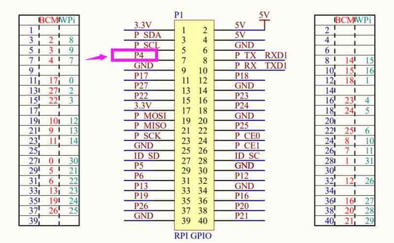
| PWR | On/off control pin, connected to P4 pin of Raspberry Pi by default |
Indicator LED Description
| PWR | Lights up when power is supplied to the 5V and GND of the module |
| NET | 64ms on/800ms off - unregistered on the network 64ms on/3000ms off - registered on the network 64ms on/300ms off - data transmission off - power off or PSM sleep mode |
Connect To Computer For Debugging
Hardware Connection
Before using the R800C module, in addition to the micro USB cable and the GSM/Bluetooth antenna, the user also needs to prepare the following items:
- One GPRS dedicated card
- UART module (CP2102 USB UART Board is recommended.)
Hardware connection operation:
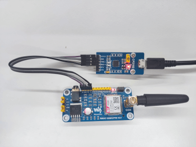
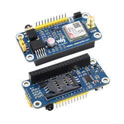
- Install the GPRS card into the card slot on the back of the module and connect the LTE antenna. (When using it, the LTE antenna must be rotated to the outside of the board, as shown on the right.)
- Connect the CP2102 module pins to serial port 1 (or serial port 2) of R800C and then connect it to the computer with a USB cable.
- Supply power to the R800C module, at this time the PWR light is red, and the NET light is off.
- Press the PWRKEY button for about 1s and release it, wait for about 2 seconds, and see that the NET light starts to flash, then the module is powered on successfully.
- Use the supporting serial port assistant to open, select the corresponding serial port and baud rate 115200, check and add carriage return and line feed, and open the extension to see the AT command for recording, click the corresponding command to send it directly.
Simple Networking Test
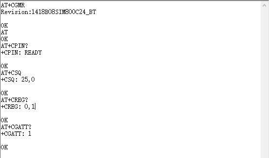
The following table lists some commonly used AT commands, which can quickly and easily detect whether the AT serial communication and network connection of R800C is normal. Before performing the network communication experiment demonstrated below, it is recommended to do a simple network test first to confirm that the network connection is normal before operating.
Related AT command details can be found in R800C Series_AT Command Manual.
| Command | Description | Return value |
| AT | AT test command | OK |
| ATE | ATE1 set echo, ATE0 disable echo | OK |
| AT+CSQ | Network signal quality query, return signal value | OK |
| AT+CGMR | Query firmware version | OK |
| AT+CREG? | Query network registration status | OK |
| AT+CGATT? | Check GPRS attachment status | OK |
Phone Call
【Make A Call】
- Correctly install the SIM card, and GSM antenna, connect the TTL serial port and connect the power supply;
- Observe whether the indicators are normal, the PWR indicator is always on, the STA indicator is always on, and the NET indicator is flashing;
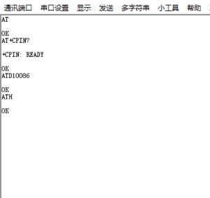
- Query the status of the SIM card, send "AT+CPIN?+Enter", return +CPIN: READY is normal;
- Dial number: "ATD10086;", here we take 10086 as an example;
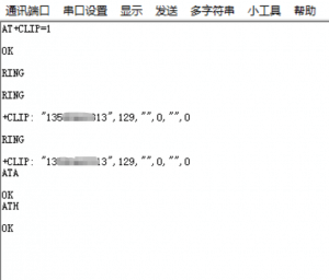
- Hang up the phone: "ATH+Enter", as shown in the figure below;
【Answer A Call】
- Set caller ID: "AT+CLIP=1+Enter"
- Connect: "ATA+Enter", hang up: "ATH+Enter"
SMS Sending and Receiving
【Send English SMS】
Test steps:
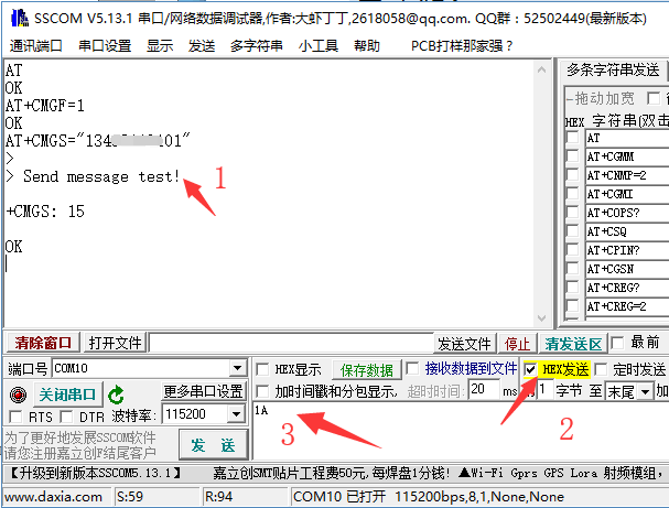
- AT+CMGF=1: set SMS mode to TEXT.
- AT+CMGS="phone number"<Enter>, set the receiver's phone number, and then return: ">".
- Send the required content, such as "Send message test!", no need to enter at the end.
- After editing the text message, send 1A in hexadecimal format to send the message.
(1A is the key value of "CTRL+Z", which is used to tell the module to perform the sending operation, and you can also send 1B, which is "ESC" to cancel operate). - After the sending is successful, the module returns +CMGS: 15 to confirm the sending is successful.
【Receive English SMS】
Test steps:
- Send a message on the mobile phone: "This is a receive test for SIM7600X!" to the test module.
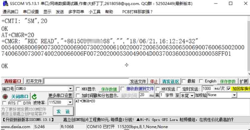
- When the message is received, the serial port will stop reporting the message, "SM", 20, which means there are 20 messages in the SM, and the message just sent is the 20th message.
- Read information: AT+CMGR=20 read the 20th information (AT+CMGL="ALL" means to read all information).
- Delete information: AT+CMGD=20, as shown in the figure below.
- Convert the displayed information into text through a code converter.
【Send Chinese SMS】
Test steps:
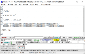
- AT+CMGF=1, set to text mode.
- AT+CSCS="UCS2" , set the message text to UCS2 code set.
- AT+CSMP=17,167,2,25 //Set text mode parameters.
- AT+CMGS="xxxxxxxxxxxxxxxxxxxxxxxxxxxxxxxxxxxxxxxxxxxxxxxx", set the UCS2 set of the receiver's phone number.
- Waiting for return>, the content of the converted information sent at this time: 005200380030003000436D4B8BD5 (R800C test).
- Enter is not required at the end, after editing the text message, send 1A to send the message in hexadecimal format.
【Recieve Chinese SMS】
- Send AT+CMGF=1 to set the text display.
- Send AT+CSCS="GSM" to set the GSM code set.
- When the message is received, the serial port will automatically report the message, "SM", 59, means that there are 59 messages in the SM, and the message just sent is the 59th.
- Read information: AT+CMGR=59 to read the 59th information (AT+CMGL="ALL" means to read all information) and convert the information into Chinese in the software, as shown in the figure below.
TCP/IP Communication
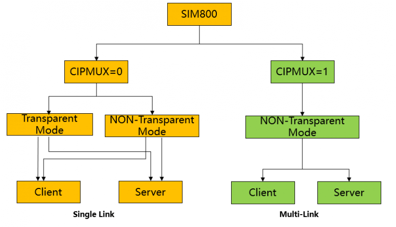
The TCP/IP application of R800 series modules has two connection modes, which can be set by the command AT+CIPMUX=<n>. When AT+CIPMUX=0, it is single-link mode; when AT+CIPMUX=1, it is the multi-link mode. The default setting is the single-link mode.
When in single link mode, R800 series modules can work in transparent transmission mode and non-transparent transmission mode. In these two transmission modes, the module can be configured as a TCP/UDP client or a TCP server.
When in multi-link mode, R800 series modules only work in non-transparent mode.
In this mode, the module can be used as an absolute TCP/UDP connection client, and it can establish a total of 6 connections; it can also be configured as a TCP server, and it can also be configured as a 5-way TCP/UDP client. R800C TCP/IP is a multi-channel client architecture by default, supporting 5 sockets in total, including TCP or UDP.
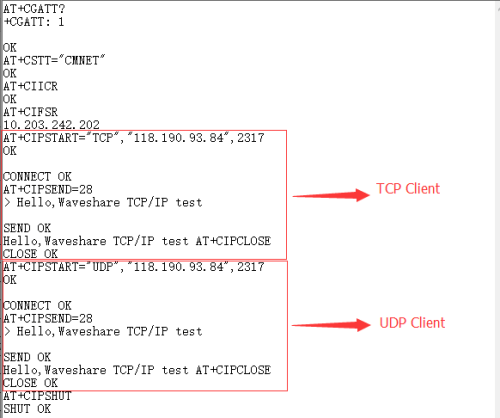
The following will focus on demonstrating the client communication of the R800C in single-link non-transparent mode and transparent mode.
For detailed instructions related to TCP/IP communication, please refer to: R800C Series_TCPIP_Application_Note.
【Client Communication In Non-transparent Mode】
Related commands:
| AT Command | Command Description | Return Value |
| AT+CGATT? | Check GPRS attachment status | OK |
| AT+CSTT="CMNET" | Set APN | OK |
| AT+CIICR | Establish a wireless link | OK |
| AT+CIFSR | Get local IP address | OK |
| AT+CIPSTART="TCP","118.190.93.84",2317 | Establish a TCP client connection | OK |
| AT+CIPSTART="UDP","118.190.93.84",2317 | Establish UDP client connection | OK |
| AT+CIPSEND=<Character length> | Send a string of specified length | OK |
| AT+CIPCLOSE | Close link communication | OK |
| AT+CIPSHUT | Close the PDP context connection | OK |
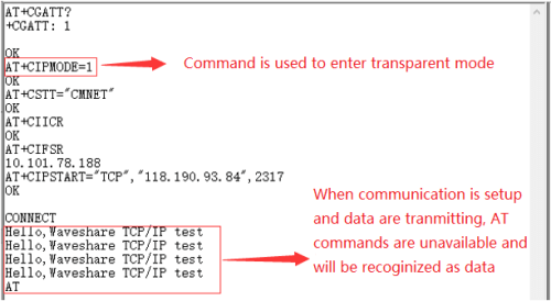
【Client Communication In Transparent Mode】
Related commands:
| AT Command | Command Description | Return Value |
| AT+CGATT? | Check GPRS attachment status | OK |
| AT+CIPMODE=1 | Set to transparent transmission mode | OK |
| AT+CSTT="CMNET" | Set APN | OK |
| AT+CIICR | Establish wireless link | OK |
| AT+CIFSR | Get local IP address | OK |
| AT+CIPSTART="TCP","118.190.93.84",2317 | Establish a TCP client connection | OK |
| AT+CIPSTART="UDP","118.190.93.84",2317 | Establish UDP client connection | OK |
| AT+CIPSEND=<Character length> | Send a string of specified length | OK |
| AT+CIPCLOSE | Close link communication | OK |
| AT+CIPSHUT | Close the PDP context connection | OK |
You can freely switch between transparent transmission mode and command mode through the following methods.
(1) If the fourth parameter of AT+CIPCCFG is 1, it supports to exit the transparent transmission mode through the escape sequence. The default escape sequence is +++. To use this sequence correctly, you must ensure that there is a 1000ms idle before the sequence and a 1000ms idle after the sequence. It should also be noted that the interval between each + should not exceed 1000ms, otherwise it may be regarded as TCP/IP data.
(2) The DTR pin of the serial port can be used. To use this method, first set up AT&D1, ground the DTR pin for at least 1 second, and then pull it high. This method can switch from data mode to command mode. The reported string "OK" indicates that the module is currently in command mode.
(3) For the TCP client connection, if the remote server disconnects, the module will automatically switch to the command mode.
(4) For the TCP server connection, if the remote client disconnects, the module will automatically switch to the command mode.
(5) Restart the module.
HTTP Communication
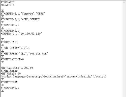
This chapter mainly introduces the HTTP communication function of the R800C module, mainly divided into HTTP GET and HTTP POST.
For detailed usage instructions of HTTP and FTP communication functions, please refer to R800C Series_IP_Application_Note.
【HTTP GET】
Related commands:
| AT Command | Command Description | Return Value |
| AT+SAPBR=3,1,"Contype","GPRS" | Configuring Bearer Scenario 1 | OK |
| AT+SAPBR=3,1,"APN","CMNET" | Configure bearer scenario APN | OK |
| AT+SAPBR=1,1 | Activate a GPRS context | OK |
| AT+SAPBR=2,1 | Query GPRS context | OK |
| AT+SAPBR=0,1 | Close the GPRS context. | OK |
| AT+HTTPINIT | Check the HTTP connection status | OK |
| AT+HTTPPARA="CID",1 | Set HTTP session parameters | OK |
| AT+HTTPPARA="URL","www.sim.com" | Set HTTP session parameters | OK |
| AT+HTTPACTION=0 | GET session start | OK |
| AT+HTTPREAD | Read data from the HTTP server | OK |
| AT+HTTPTERM | End HTTP service | OK |
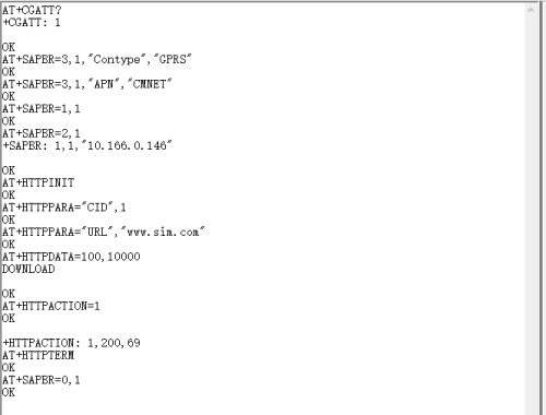
【HTTP POST】
Related commands:
| AT Command | Command Description | Return Value |
| AT+SAPBR=3,1,"Contype","GPRS" | Configuring Bearer Scenario 1 | OK |
| AT+SAPBR=3,1,"APN","CMNET" | Configure bearer scenario APN | OK |
| AT+SAPBR=1,1 | Activate a GPRS context | OK |
| AT+SAPBR=2,1 | Query GPRS context | OK |
| AT+SAPBR=0,1 | Close the GPRS context. | OK |
| AT+HTTPINIT | Check HTTP connection status | OK |
| AT+HTTPPARA="CID",1 | Set HTTP session parameters | OK |
| AT+HTTPPARA="URL","www.sim.com" | Set HTTP session parameters | OK |
| AT+HTTPDATA=100,10000 | Upload 100 bytes of data, wait for 10000 milliseconds | OK |
| AT+HTTPACTION=1 | GET session start | OK |
| AT+HTTPTERM | End HTTP service | OK |
Connect to Raspberry Pi
Hardware Connection
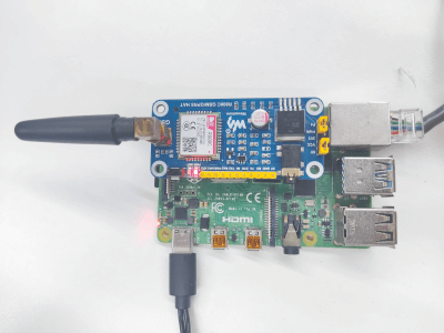
The R800C GSM GPRS HAT has a Raspberry Pi GPIO interface onboard, which can be directly plugged into various versions of the Raspberry Pi;
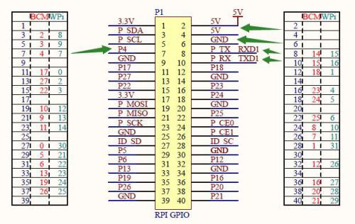
The following table shows the connection between Raspberry Pi pins and module pins (Raspberry Pi 3B+):
| R800C GSM/GPRS HAT | Raspberry Pi |
| 5V | 5V |
| GND | GND |
| RXD | TXD (corresponding to 14 of BCM) |
| TXD | RXD (corresponding to 15 of BCM) |
| PWR | P7 (corresponding to P4 of BCM) |
Software Setting
【Pin initialization】
The factory default PWR pin of the module is selected to the P4 pin of the Raspberry Pi through a jumper cap. In order to ensure that the R800C GSM/GPRS HAT can work normally after being connected to the Raspberry Pi, it is necessary to initialize the level of the Raspberry Pi pin output.
The reference operation is as follows:
- Download the Raspberry Pi demo, and copy the entire folder of R800C to the /home/pi/ path.
- The command line enters the /home/pi/ directory and executes the command
chmod 777 pi_gpio_init.sh
- Set the boot initialization script, and run the command:
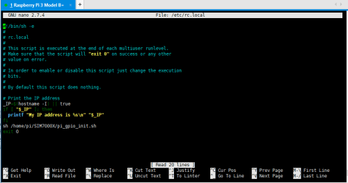
sudo nano /etc/rc.local
- Add before exit 0 (as shown in the figure below):
sh /home/pi/SIM800C/pi_gpio_init.sh
【Serial port configuration】
Since the Raspberry Pi serial port is used for terminal debugging by default, if you want to use the serial port, you need to modify the Raspberry Pi settings.
- Execute the following command to enter the Raspberry Pi configuration:
sudo raspi-config
- Select Interfacing Options ->Serial ->no -> yes to turn off the serial port debugging function.
- Open the /boot/config.txt file, find the following configuration statement to enable the serial port, if not, add it at the end of the file:
enable_uart=1
- Restart to take effect.
Raspberry Pi Minicom Debugging
Insert the module into the Raspberry Pi, and install minicom. (Minicom is a serial port debugging tool on the Linux platform.)
sudo apt-get install minicom
Execute minicom -D /dev/ttyS0 to enter the minicom serial port debugging interface.
The default baud rate is 115200, ttyS0 is the serial port of Raspberry Pi 3B/3B+, Zero/2B is ttyAMA0.
Raspberry Pi pppd Dial-up Internet Access
In the Raspberry Pi Raspbian system, R800C supports pppd dial-up Internet access via serial port, and the steps are shown below:
1. Install PPP.
sudo apt-get install ppp
2. Switch to root user.
sudo su
3. Enter /etc/ppp/peers directory, copy provider file and name it as gprs.
cd /etc/ppp/peers
cp provider gprs
4. Open and edit gprs (here use nano to open as an example).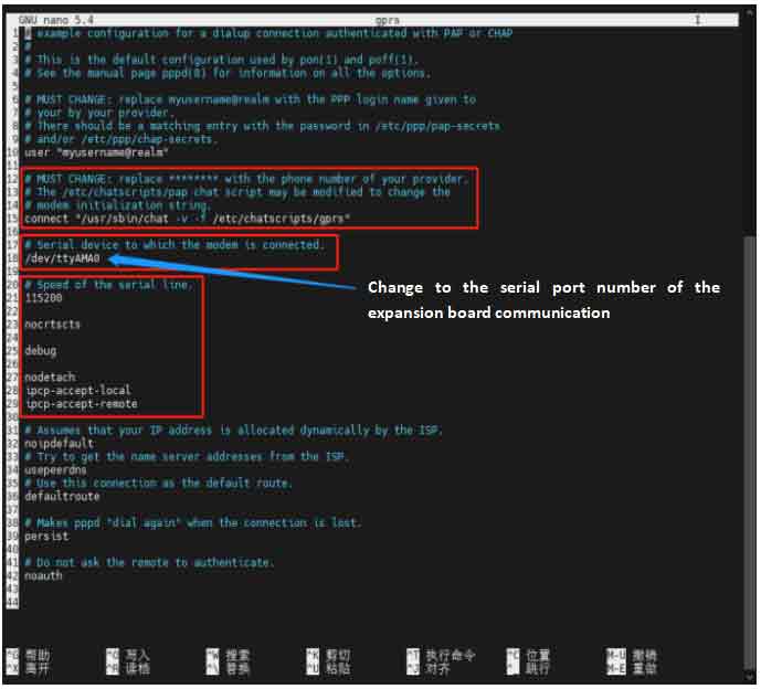
5. Run the command to start dialing in the background.
pppd call gprs &
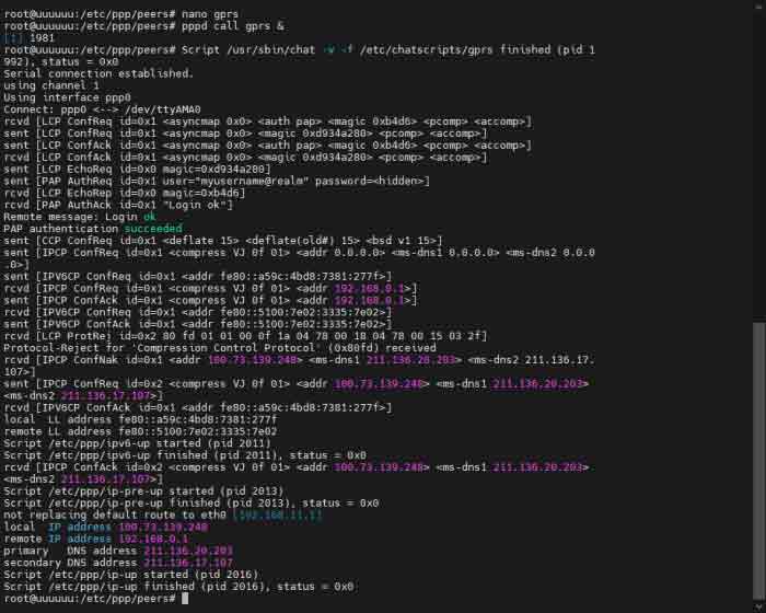
6. Run the ifconfig command to see the ppp0 network card.
Ifconfig
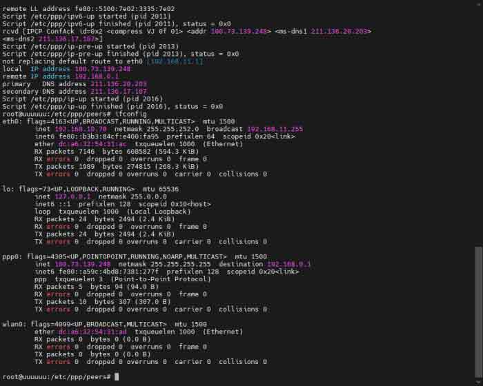
7. If you cannot access the Internet normally at this time, it will prompt that DNS cannot be resolved, you can add the following command to configure the routing table.
route add -net 0.0.0.0 ppp0
Raspberry Pi BCM2835 Demo
After using minicom to communicate with the serial port of the HAT, you need to restart the HAT first, and vice versa.
Install bcm2835 library
Download the demo, after decompression, enter the directory under R800C_python:
 cd R800C_GSM_GPRS_HAT_Code/bcm2835/bcm2835
 chmod +x configure && ./configure && sudo make && sudo make install
 #Wait for the bcm2835 library to be compiled and installed
If there is a problem in the compilation and installation process, please refer to the FAQ.
HAT Basic Communication Demo
Enter basic AT commands and receive replies from the HAT.
 make clean && make
 sudo ./main
After running the demo, the demo will first check whether the serial communication with the module is normal. After the communication is normal, it will automatically send a series of commands to check the status of the module; after completing the check, you can input AT commands to control the module according to the prompts.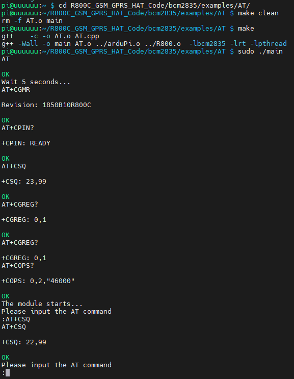
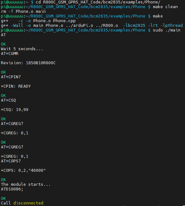
Phone Call Demo
After checking that the communication status of the HAT is normal, insert the headphone on the HAT, run this demo, and complete the dialing. After a period of time, the phone will automatically hang up. The dialed phone number and the time before hanging up can be set in the demo file.
 make clean && make
 sudo ./main
Sending English SMS Demo
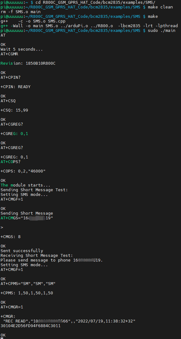
After checking that the communication status of the HAT is normal, run this demo, and the demo will return the success sign after sending successfully according to the pre-set SMS recipient number and English SMS content. The recipient of the SMS and the content of the English SMS can be modified in the demo.
 make clean && make
 sudo ./main
Raspberry Pi Python Demo
After using minicom to communicate with the serial port of the expansion board, you need to restart the expansion board first, and vice versa.
Download the demo, after decompression, enter the python directory:
cd R800C_GSM_GPRS_HAT_Code/python
HAT Basic Communication Demo
Enter basic AT commands and receive replies from the HAT.
python AT.py
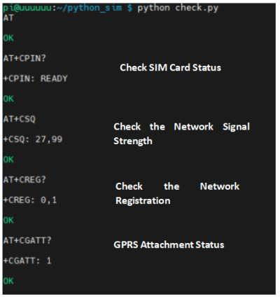
Check Status Demo
Send a series of commands to check the status of the HAT and obtain ITS connection information.
python check.py
Phone Call Demo
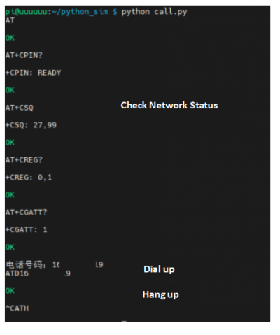
After checking that the communication status of the HAT is normal, insert the headphone, run this demo, enter the correct phone number according to the prompts, and complete the dialing; use ctrl+C to hang up the phone and terminate the demo.
python call.py
Sending English SMS Demo
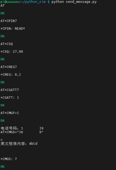
After checking that the communication status of the HAT is normal, run this demo, input the SMS recipient number and the content of the English SMS according to the prompts, and the demo will end automatically after the sending is successful.
python send_message.py
If the communication status checks the result of the HAT is normal, but the sending of the SMS fails, you can try to change the SMS center number (do not modify it unless necessary).
nano send_message.py #Here we use nano as an example, other editors can also be used


