


- sales/support
Google Chat:---
- sales
+86-0755-88291180
- sales01
sales@spotpear.com
- sales02
dragon_manager@163.com
- support
tech-support@spotpear.com
- CEO-Complaints
zhoujie@spotpear.com
- Only Tech-Support
WhatsApp:13246739196
- Purchase/Shipping/Refund
WhatsApp:13424403025
RPi-Zero-Dual-ETH User Guide
一、Introduction
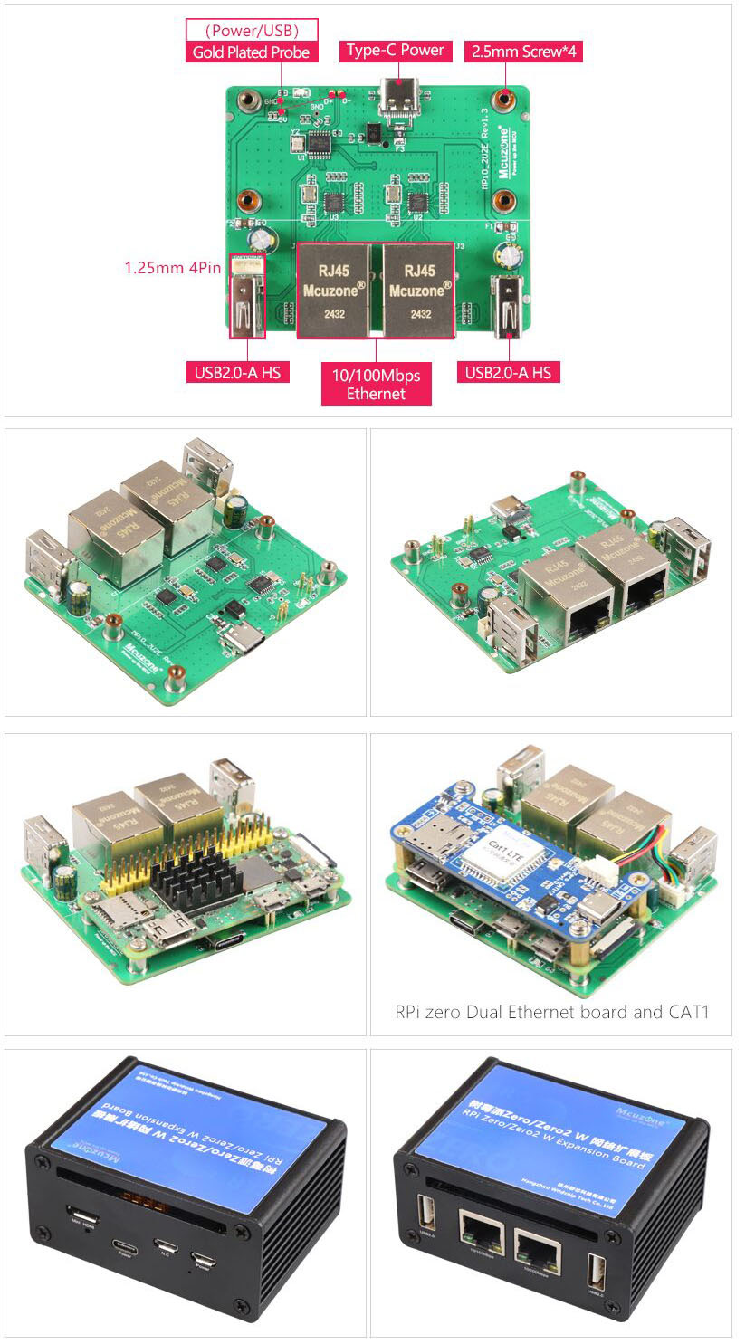
The Raspberry Pi Dual Network Expansion Board is an expansion board designed specifically for the Raspberry Pi Zero series. It supports all versions of the Raspberry Pi Zero series, including Zero, Zero W, Zero WH, and Zero 2W. It also supports some domestically produced Raspberry Pis with the same test points, such as the Orange Pi Zero2W.
This expansion board connects to the Zero series via gold-plated pins. Two pins are used for power supply, and the other two are used for USB communication. Note that the MicroUSB (OTG) port on the Zero cannot be connected to other USB devices or USB cables, otherwise the expansion board's USB will not work.
Power supply: It can be powered via the MicroUSB port marked PWR on the Raspberry Pi Zero, or via the USB-C port on the expansion board. You can only use one of them at a time, and they cannot be used simultaneously.
The expansion board is essentially a USB hub, using Zero's own USB OTG port as the host. It expands to four ports via USB hub: two for expanding USB-to-100Mbps Ethernet adapters, and two as USB 2.0-A host ports. The new version has a 1.25mm 4-pin connector reserved on one of the USB 2.0-A ports, allowing expansion with devices such as the built-in 4G network adapter.
二、Hardware resources
1. Power and communication are achieved via gold-plated pins and Zero series connectors;
2. Power supply: Onboard USB-C 5V power supply or Zero's own PWR MicroUSB power supply, choose one of the two and do not use them simultaneously;
3.Two 100Mbps Ethernet ports;
4. Both USB 2.0-A host ports are equipped with 2A fuses; the new version reserves a 1.25mm 4pin interface on one of the USB 2.0-A ports, which share a set of USB signals and can be used in one of the two ports, and can be expanded to 4G CAT1.
5. Dimensions: 70*56mm, 4 M2.5 mounting posts for assembling the Raspberry Pi Zero;
6. The PCB board is UL and RoHS certified and has a fire rating of 94V-0.
7. Optional all-aluminum alloy shell, shell dimensions: 80*58*38mm.
三、Using Raspberry Pi OS
This document is based on the hardware of the Raspberry Pi Zero 2W.
The system uses Raspberry Pi OS, version 2023-05-03-raspios-bullseye-arm64.img.xz.
(If using a Raspberry Pi Zero series board, only 32-bit systems are supported. Please pay attention to the version you download.)
Raspberry Pi OS download address:
https://www.raspberrypi.com/software/operating-systems/#raspberry-pi-os-64-bit
3.1Check hardware
3.1.1 Check USB devices
Open the terminal on your Raspberry Pi OS and enter the command.lsusb,As shown in the image below:
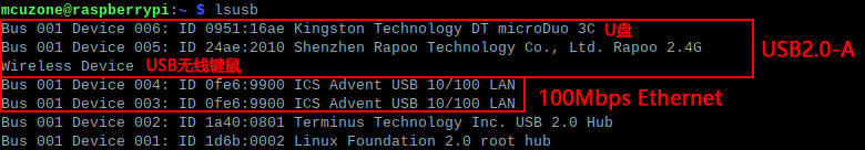
As you can see, the system has identified two 100Mbps network cards.
3.1.2 Check network equipment
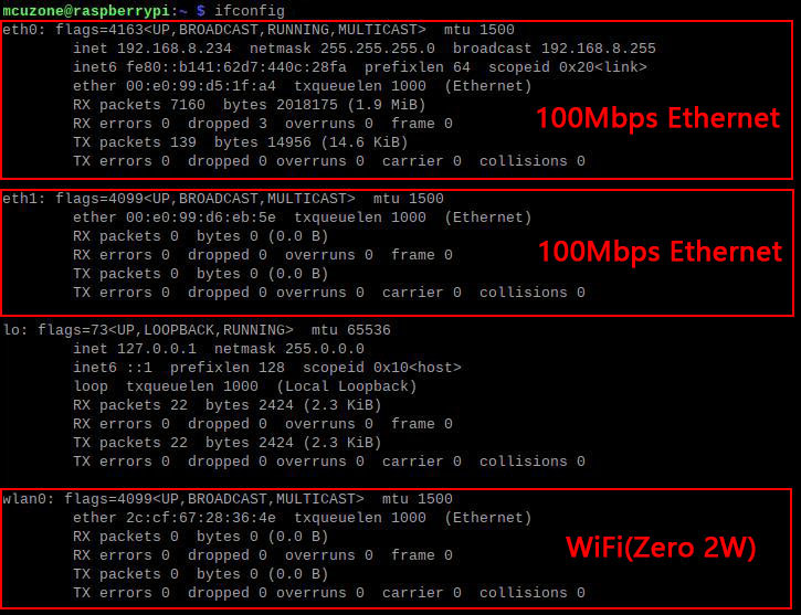
Open the terminal on your Raspberry Pi OS and enter the command.ifconfig,As shown in the image below:

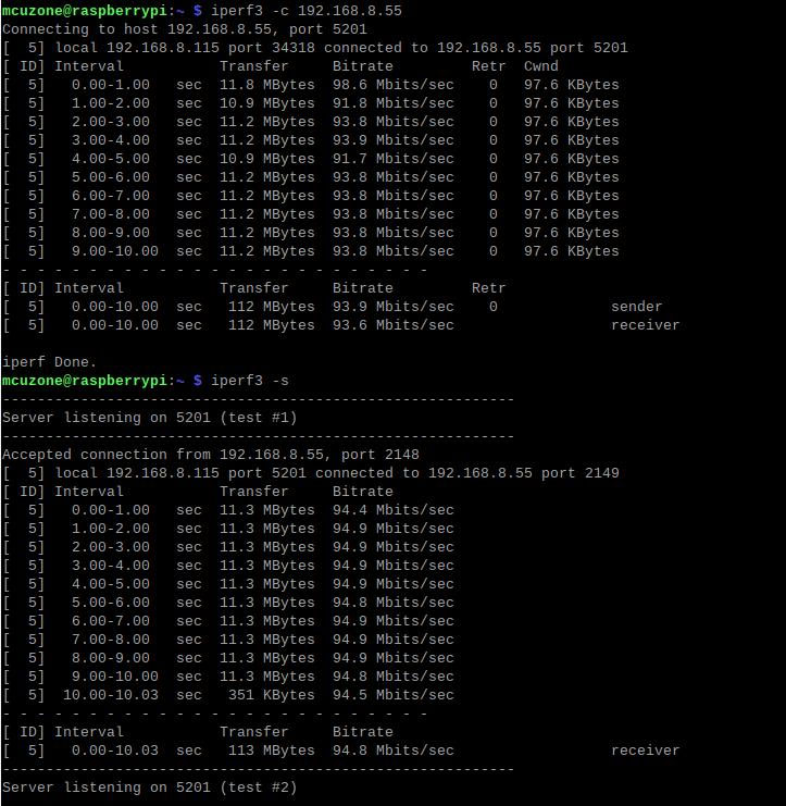
We used iperf3 to test the speed of two Ethernet networks.
Download iperf3 for Windows:
http://www.mcuzone.com/down/Software.asp?ID=10000634
Installing iperf3 on Linux:
sudo apt-get install iperf3

100Mbps Ethernet speed test results:
eth0: Client mode approximately 93Mbps, Server mode approximately 94Mbps.
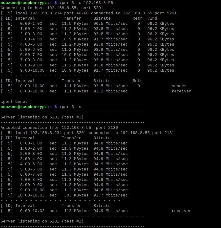
eth1: Client mode approximately 93Mbps, Server mode approximately 94Mbps.
3.2 Ethernet usage
If one network port uses the internal network and the other uses the external network, or if the two network ports are on different network segments, you need to manually set the two network ports to different IP addresses.
By default, the two wired network ports automatically assign IP addresses after the Raspberry Pi system starts up. If we need to set the IP address to a user-selected static IP address, we need to manually set the IP address.
Right-click the network icon in the upper right corner of the desktop and open "Wireless & Wired Network Settings...":
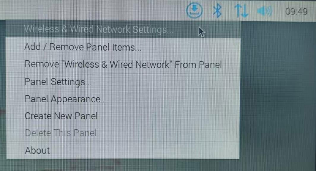
Select the network interface you want to modify, for example, "eth0", then enter the network parameters, click "Apply" to save, and "Close" to close.
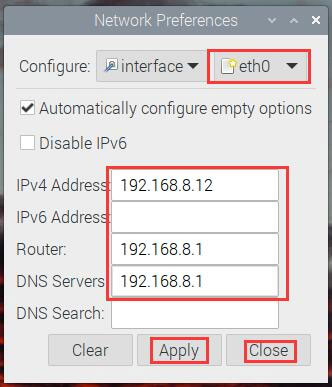
Re-plug the network cable to obtain a new address, thus completing the manual IP setting for the first network card (here set to 192.168.8.12).
If you want to set a custom static IP address for the second network interface card (NIC), perform the same operation on "eth1" (here, set it to 192.168.8.13), and then execute the following command in the terminal.ifconfig:
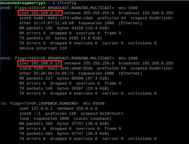
It is evident that the IP addresses of both network cards are set to the specified static IP addresses.
3.4 Frequently Asked Questions
3.4.1 Startup issues
If your system gets stuck at the Raspberry Pi logo during startup and fails to boot:
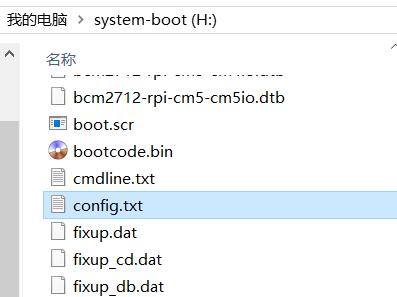
If you experience repeated restarts, or if the keyboard, mouse, and 4G module are unusable after startup, please carefully check if the pins are aligned with the gold-plated contacts. Also, please open the config.txt file in the root directory of the TF card's system partition on your PC and check the USB initialization script.
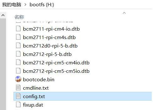
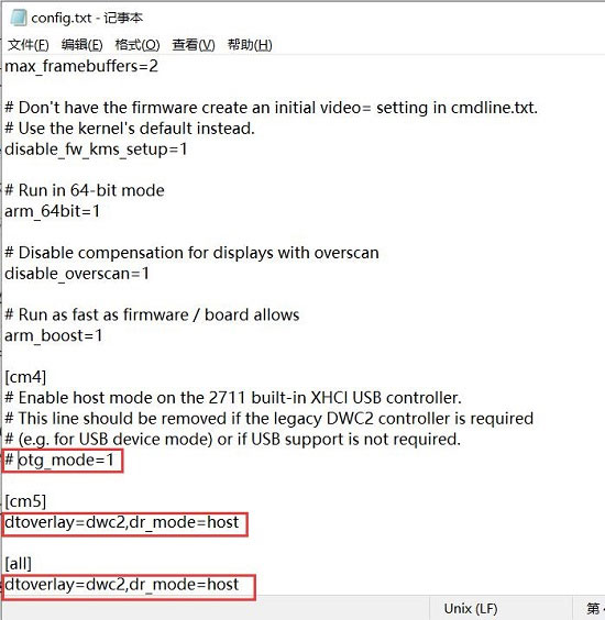
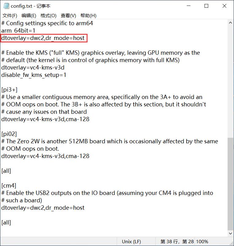
Please confirm that the three areas highlighted in red in the image below are all configured to be fully active. If not, please manually add them to be fully active and save the file: # otg_mode=1 (It is recommended to comment this out).
dtoverlay=dwc2,dr_mode=host(Both places must be included)
3.4.2 Network card priority settings
If multiple networks exist, there is a network card priority issue, i.e., which network card is used by default to access the internet.
Now connect to the wired network (eth1) and also to the 4G CAT1 (eth2). Check the default internet connection device; it should be usable.routeCommands, such as:
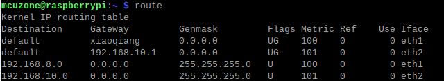
At this point, eth1 is ranked first, so it defaults to accessing the internet via a wired network.
Install the udhcpc software and execute the following command in the Raspberry Pi terminal:
sudo apt install udhcpc

If you need to use 4G CAT1 for internet access by default, you can run:
sudo udhcpc -i eth2
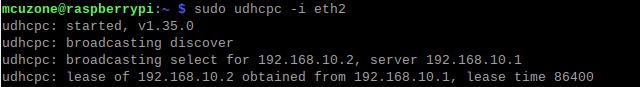
Then run it again.route
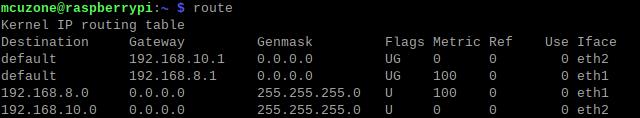
At this time, eth2 is ranked first, so it will access the Internet via 4G CAT1 by default.
四、Using the Ubuntu Server system
This document uses hardware based on Raspberry Pi Zero 2W and Ubuntu Server LTS server version; before use, the system's USB and Ethernet ports need to be configured.
ubuntu-24.04-preinstalled-server-arm64+raspi.img.xz
Ubuntu system download address:
https://ubuntu.com/download/raspberry-pi
4.1 Configuration System
4.1.1 Configure USB
After the Ubuntu Server system flashing is complete, please open the config.txt file in the root directory of the TF card system partition on your PC and check the USB initialization script. Ubuntu Server initializes the USB twice; the first time it is not configured in host mode. You need to confirm that the area highlighted in red in the image below is configured completely. If not, please manually add the complete configuration. If you do not modify it, the USB device will not be usable.:
dtoverlay=dwc2,dr_mode=host
4.1.2 Configure username and password
Insert the TF card into the Zero 2W and boot the system. Upon first boot, you will be prompted to log in. The username and password are both "ubuntu". After successful login, you will be prompted to change the password.

After the modifications are complete, you will automatically enter the system.
4.1.3 Configure Ethernet
For Raspberry Pi Zero series development boards, the Ethernet interface is disabled by default and requires further configuration before it can be used.
Connect any Ethernet cable to the upstream router, then execute `ip addr` to view and record the network interface card (NIC) name:
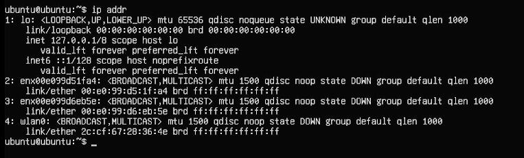
Among them, network cards No. 2 and No. 3 (enx00e099d51fa4, enx00e099d6eb5e) are USB to 100 Mbps Ethernet adapters.
Then run the following command to open the network interface configuration file:
sudo nano /etc/netplan/50-cloud-init.yaml
Edit the network interface configuration file as shown in the image below:
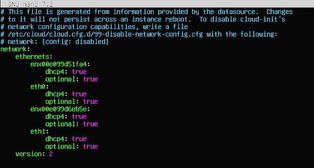
Save and exit, then restart.
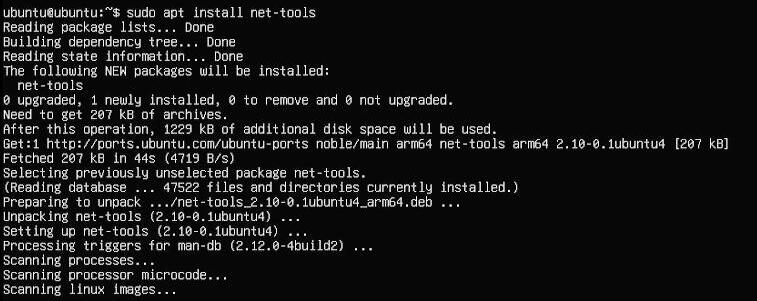
After restarting, you can connect to the internet. Install the net-tools utility for use.
sudo apt install net-tools
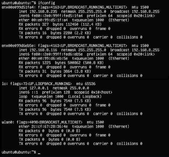
After configuration, connect the other Ethernet port to the upstream router, execute the command `ifconfig`, and check the information of both network cards. Both should be able to obtain IP addresses.
4.2 Ethernet testing
After the network card correctly obtains an IP address, any one or both network ports connected to the upstream router can successfully ping the external network address, such as:
ping www.mcuzone.com
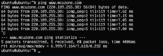
If the ping is successful, it means the network connection is successful.
Download iperf3 for Windows:
http://www.mcuzone.com/down/Software.asp?ID=10000634
Installing iperf3 on Linux:
sudo apt-get install iperf3
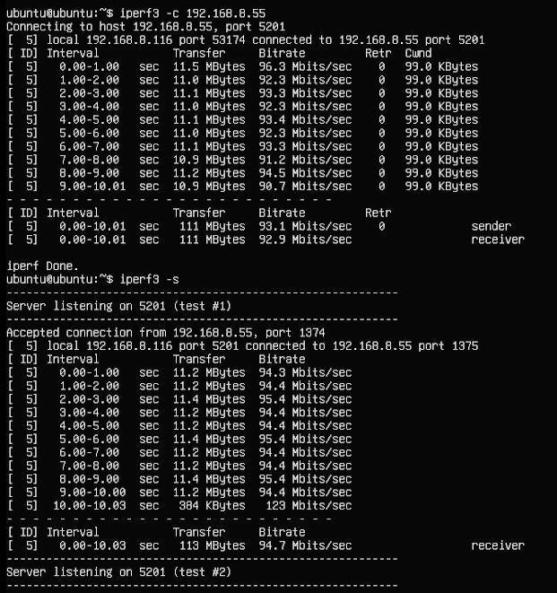
100Mbps Ethernet speed test results:
Network adapter #2: Approximately 93Mbps in Client mode, approximately 94Mbps in Server mode.
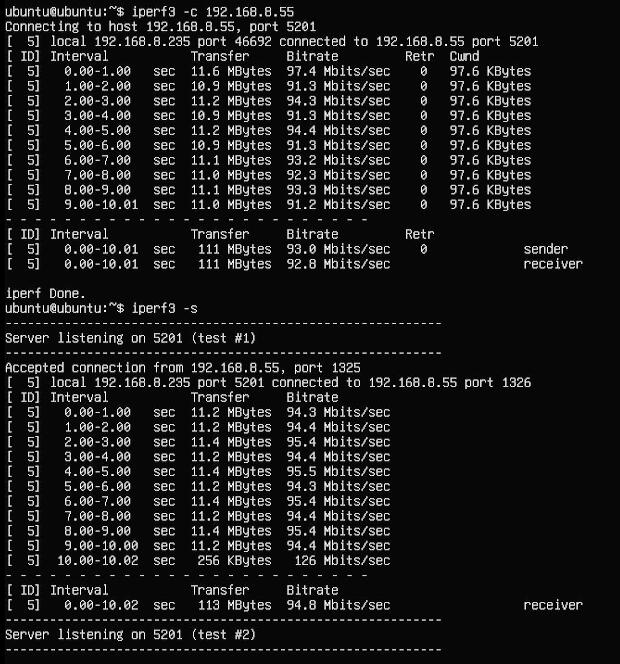
Network adapter #3: Approximately 93Mbps in Client mode, approximately 94Mbps in Server mode.
五、4G operation
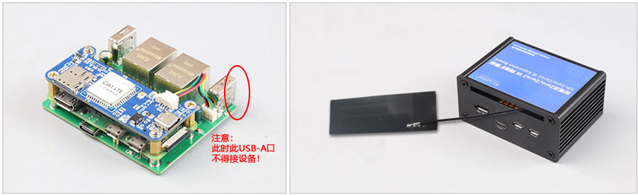
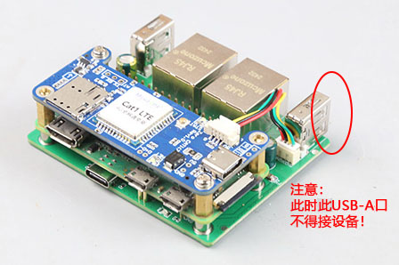
Our RPi0-CAT1 module is designed for use with an expansion board and can be assembled together into the enclosure. Note: Do not connect any USB devices to the USB-A port corresponding to the 1.25mm-4P connector; otherwise, 4G will not function.
Different Raspberry Pi operating systems have different network management strategies. Based on a 64-bit operating system, the test results are as follows:
| System version | Test Results |
| 2023-02-21-bullseye | Driver-free and dial-free, automatic recognition, plug and play, and automatic network connection. |
| 2023-05-03-bullseye | |
| 2023-12-05-bookworm | It requires no drivers or dial-up connection and is automatically recognized, but it may encounter network connection failures, requiring the system to install DNS software. |
| 2024-07-04-bookworm | |
| 2024-11-19-bookworm | |
| 2025-05-13-bookworm | |
| 2025-10-01-trixie |
5.1 4G module test of Raspberry Pi OS
5.1.1 Module connection
Without plugging in a network cable, executing `ifconfig -a` in the Raspberry Pi terminal shows that the 4G module (eth2) has correctly obtained an IP address.
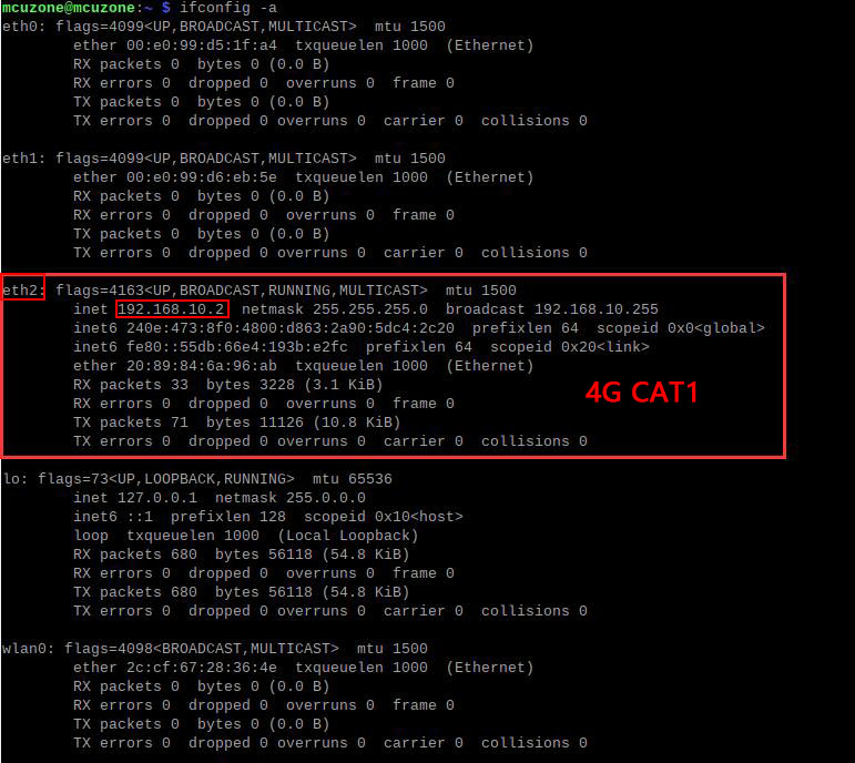
The status LED is as follows:
A flashing state of 1.8 seconds on and 0.2 seconds off (or you can judge by the fact that the on time is longer than the off time) indicates that the 4G module is connected to the network;
If the flashing status is 1.8 seconds on and 0.2 seconds off, it indicates a problem with the SIM card or network. Please check the SIM card and antenna.
5.1.2Network testing
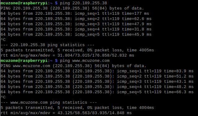
After the 4G module successfully obtained an IP address, we tested pinging external IP addresses and domain names, such as:
ping 220.189.255.38
ping www.mcuzone.com
All were successful, indicating that the 4G module is working properly.
Some versions of the Raspberry Pi system can only ping IP addresses, but will encounter network failures and report DNS errors when pinging domain names.
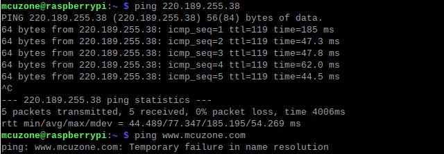
At this point, udhcpc needs to be used. Execute:
sudo udhcpc -i eth2

After the process is complete, ping the IP address and domain name again, and it should succeed.
5.2 4G module test on Ubuntu system
5.2.1 Module configuration
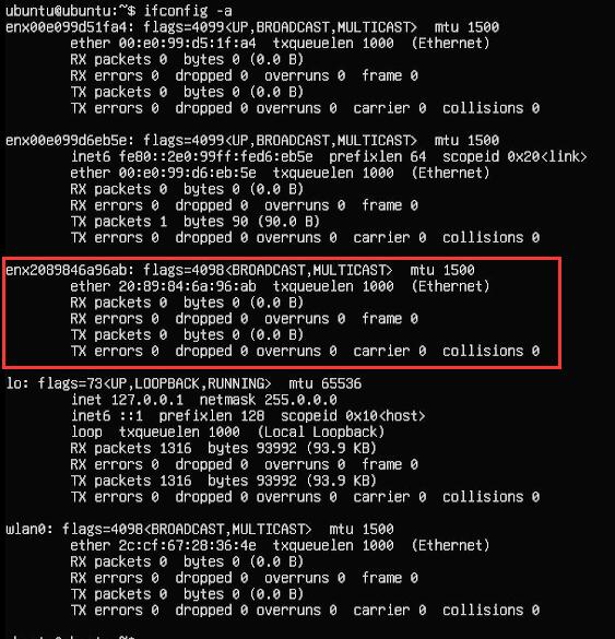
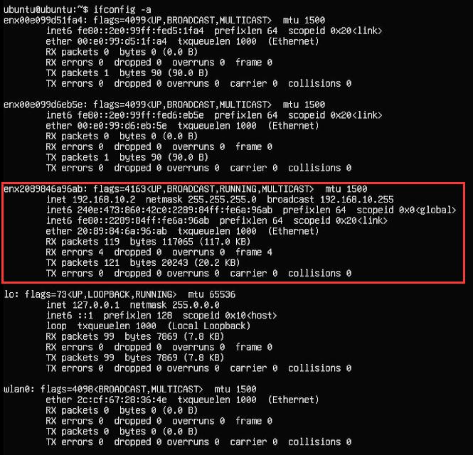
Without plugging in the network cable, execute `ifconfig -a`. Comparing it with the two wired network cards from before, we can see that the 4G module is enx2089846a96ab:
Run the following command to open the network interface configuration file:
sudo nano /etc/netplan/50-cloud-init.yaml
Edit the network interface configuration file as shown in the image below:

Save and exit, then restart.
Execute commandifconfig -a,You can view the information of the external 4G module to obtain its IP address:
5.2.2 Network testing
After the 4G module correctly obtains an IP address, we can ping an external network address, such as:
ping www.mcuzone.com

Since the 4G module is the only network connection that can access the internet at this time, a successful ping indicates that the 4G CAT1 network connection is successful.
The network card priority settings for the Ubuntu Server system are the same as those for the Raspberry Pi OS. Please refer to the relevant content in the previous chapter.
5.3 Use AT commands
The usage of AT commands is the same on both Raspberry Pi OS and Ubuntu Server systems. This chapter is based on Raspberry Pi OS. The steps are as follows:
After the system powers on and boots up, execute the following command in the Raspberry Pi terminal:
lsusb

Note down the 4G module's ID value: 19d1 0001
Use the following command to open the serial port, where the value after `echo` is the ID value recorded above:
sudo modprobe option
sudo sh -c 'echo 19d1 0001 > /sys/bus/usb-serial/drivers/option1/new_id'

Then execute the following command in the Raspberry Pi terminal:
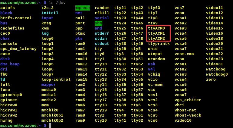
ls /dev
At this point, you should see three devices under the dev device: ttyACM0-2
Install the serial port tool minicom:
sudo apt-get install minicom

By default, the serial port for AT commands is ttyACM0.
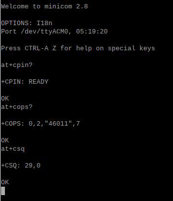
Open the AT command serial port using minicom:
sudo minicom -D /dev/ttyACM0
(Note that typically three ports, ttyACM0-2, will appear. The AT port in a typical system is ttyACM0. If that doesn't work, try other ports such as ttyACM2. If you have multiple USB-to-serial devices, you'll need to try more until you find the correct AT port.)
Entering the AT command once may not produce any output. If you enter the command "at" and press Enter, and it returns "OK", then it's working correctly. To view the output, type the command "ate1" and press Enter. Then type other commands and press Enter to see the results.
Commonly used AT commands:
1. Check if the SIM card is recognized:
at+cpin?
A "ready" return value indicates the card has been recognized; an "error" return value indicates the hardware needs to be checked.
2. Check antenna signal quality:
at+csq
A return value of 26-31 indicates a strong signal (31 for a full signal); a return value of 20-25 indicates a weak signal; and a return value below 20 indicates a poor signal or that the antenna is not connected.
3. Check the network registration status:
at+cops?
Normally, it should return the carrier code and 7, where 7 represents 4G.
Note that only the at+csq command above does not require a question mark; the other two commands do require a question mark.
4. Check the IMEI code of the 4G module:
at+cgsn
5. Reboot the 4G module (sometimes hot-swapping or re-inserting the SIM card may not work; you can use the reset command to reset the module):
at+reset
6. Turn off radio frequency:
at+cfun=0
Enable radio frequency:
at+cfun=1
The two commands above, when used in pairs, can re-register the 4G module without restarting it.
7. APN settings
Regular mobile phone SIM cards can be used directly without any settings; some IoT cards require APN settings to be used. The following is a reference provided by the user, but the specific APN code needs to be provided by the SIM card operator.
Mobile SIM card:
AT+CPNETAPN=0,"cmnet","",""
Telecom card:
AT+CPNETAPN=0,"ctnet","",""
六、Using OpenWrt
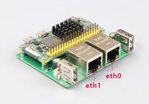
The expansion board, when paired with a Raspberry Pi Zero 2W, has two Ethernet ports that can be configured as a switch with one input and one output. One port serves as the WAN port (connecting to the upstream router), and the other as the LAN port for connecting to a PC.
The OpenWrt system used in this article was compiled by our company, version: openwrt-bcm27xx-bcm2709-rpi-2-squashfs-sysupgrade-linux-6.1.98-20240723.img.gz
6.1 Login System
Connect the 100Mbps Ethernet port eth0 on the expansion board to the PC:
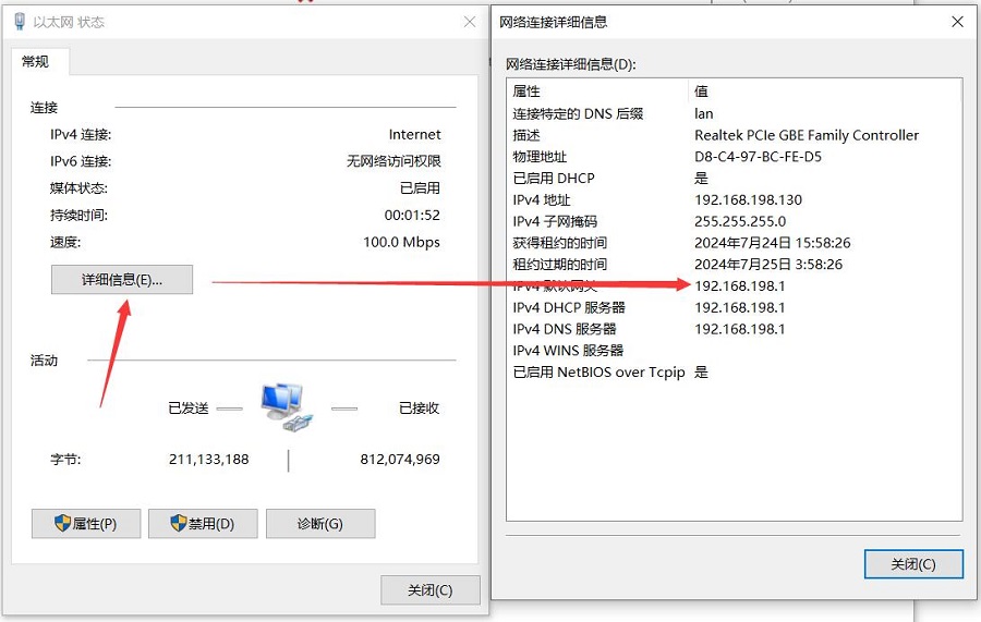
After the system starts, find Network and Internet in Windows settings, open the connected network under Ethernet, and view the IP address of the default gateway. This address is the address of the OpenWrt system's backend configuration page, as shown in the figure. The address tested in this article is 192.168.198.1.
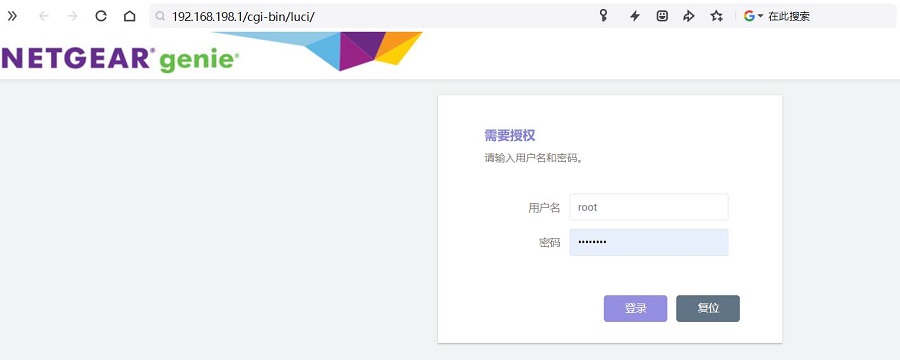
Then open a web browser and enter 192.168.198.1 to log in to the system. The default username is root and the default password is password.
6.2 Test Ethernet
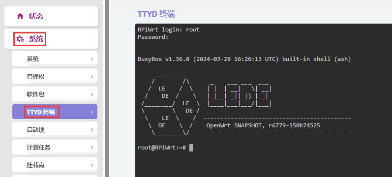
Access "System - TTYD Terminal", log in to the terminal using the username "root" and password "password".
执行ifconfig:
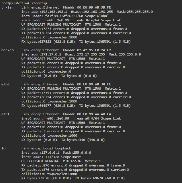
eth0 is the WAN port, and eth1 is the LAN port.
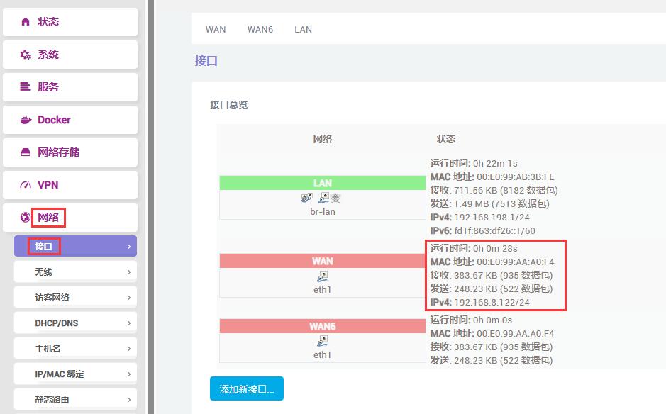
Connect eth1 to the upstream router, then click "Network - Interfaces". After a short wait, we can see that the WAN port has correctly obtained an IP address.
Access "System - TTYD Terminal", log in to the terminal using the default username and password, and ping an external network address from the terminal:
ping www.mcuzone.com
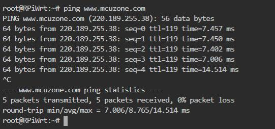
A successful ping indicates that the network is functioning normally.
Open on PChttps://www.speedtest.cn/Speed tests were conducted, and the results are as follows:

Note: Ethernet network speed tests are affected by network signal strength and testing methods; please refer to actual speeds.
6.3 Testing USB connection to 4G module
Connect the external 4G module to the expansion board. This document uses the 4G CAT1 module for testing. Note: Do not connect any USB devices to the USB-A port corresponding to the 1.25mm-4P; otherwise, the 4G will not work.
We can configure 4G CAT1 as another WAN port.
Without connecting a network cable to eth0, boot the system, log in to the TTYD terminal, and execute...ifconfig -a:
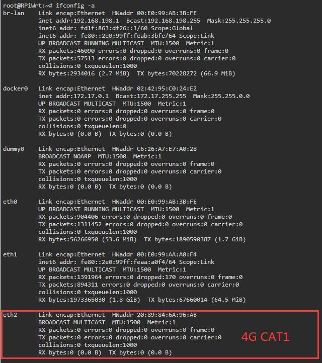
eth2 is 4G CAT1.
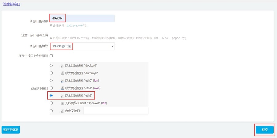
Click "Network - Interfaces", then click "Add New Interface":

Please follow the steps shown in the image below (the "Name" can be customized), and then click "Submit" after completing the settings:
In the "Firewall Settings", set the firewall zone to WAN, and then click "Save & Apply".
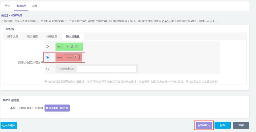
Then you will be automatically redirected to the interface page. After a short wait, you will see that the 4GWAN has correctly obtained an IP address.

Access "System - TTYD Terminal", log in to the terminal using the default username and password, and ping an external network address from the terminal:
ping www.mcuzone.com
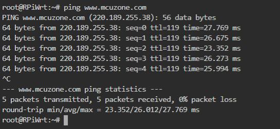
If the ping is successful, it means that the 4G CAT1 is working properly.
Open on PChttps://www.speedtest.cn/Speed tests were conducted, and the results are as follows:
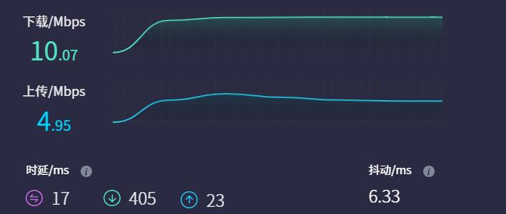
Note: 4G network speed tests are affected by network signal strength and testing methods; please refer to actual speeds.
Support
Monday-Friday (9:30-6:30) Saturday (9:30-5:30)
Email: services01@spotpear.com

[Tutorial Navigation]
- 一、Introduction
- 二、Hardware resources
- 三、Using Raspberry Pi OS
- 四、Using the Ubuntu Server system
- 五、4G operation
- 六、Using OpenWrt
- Support