- sales/support
Google Chat:---
- sales
+86-0755-88291180
- sales01
sales@spotpear.com
- sales02
dragon_manager@163.com
- support
tech-support@spotpear.com
- CEO-Complaints
zhoujie@spotpear.com
- Only Tech-Support
WhatsApp:13246739196
- Purchase/Shipping/Refund
WhatsApp:13424403025
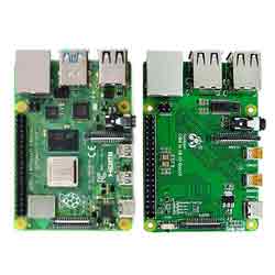
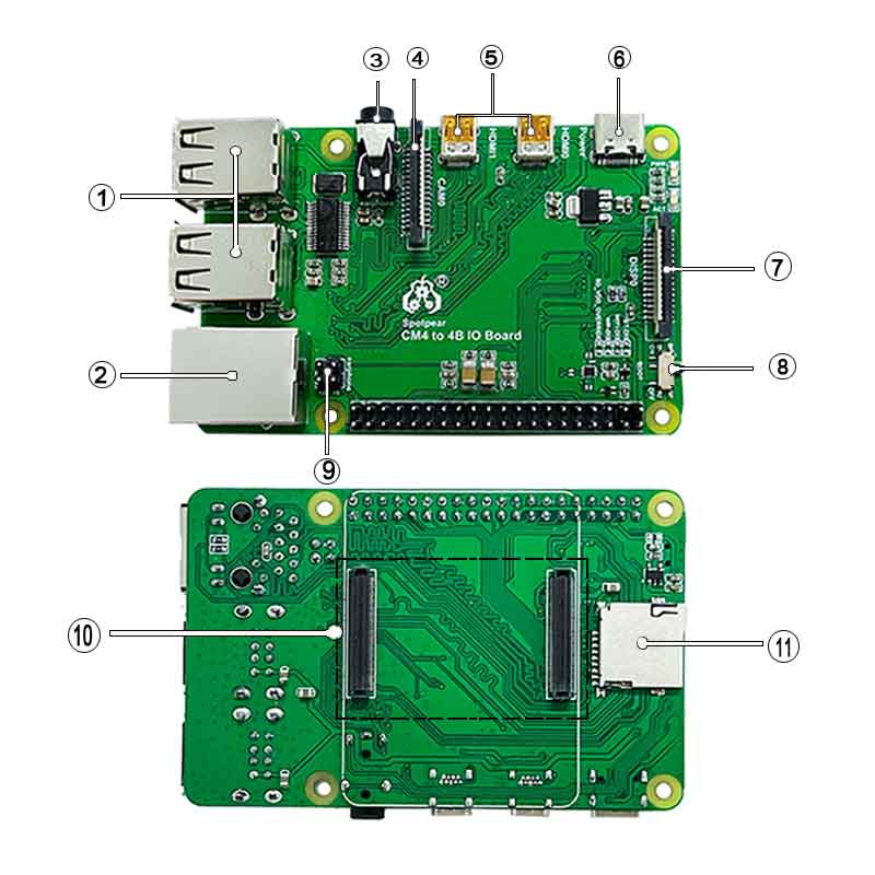
Raspberry Pi CM4 to 4B IO Board User Guide
Features
This product is suitable for customers with the following needs:
- Raspberry Pi CM4 IO board. Compatible with 4B Size and functions same as much as possible.
- USB HUB extends USB 2.0 x 4
- Rj45 network port
- GPIO audio headphone (occupying GPIO18 and GPIO19)
- Camera and DSI interface.
Introduction
CSI DSI
Configuration
CSI and DSI are disabled by default. When using camera and DSI, three I2C devices, I2C-10, I2C-11, and I2C-0, will be occupied.
Start up as follows:
wget https://www.waveshare.net/w/upload/7/75/CM4_dt_blob_Source.zip
 unzip -o  CM4_dt_blob_Source.zip -d ./CM4_dt_blob_Source
 sudo chmod 777 -R CM4_dt_blob_Source
 cd CM4_dt_blob_Source/
 #If using two cameras and DSI0 execute
 sudo  dtc -I dts -O dtb -o /boot/dt-blob.bin dt-blob-disp0-double_cam.dts
 #If executed with two cameras and DSI1
 sudo  dtc -I dts -O dtb -o /boot/dt-blob.bin dt-blob-disp1-double_cam.dts
 #When using any DSI, HDMI1 has no image output, even if you do not connect the DSI screen, as long as the corresponding file is compiled, then HDMI1 will not output.
 #If you need to restore, delete the corresponding dt-blob.bin Just: sudo rm -rf /boot/dt-blob.bin
 #After the execution is complete, turn off the power and restart the CM4
Old version(Buster)
The camera needs to run raspi-config, select Interfacing Options->Camera->Yes->Finish-Yes, reboot the system, open the enable camera, and then restart to save the changes.
Testing the Raspberry Pi Camera
View the first connected camera screen:
sudo raspivid -t 0 -cs 0
View the picture of the second camera connected:
sudo raspivid -t 0 -cs 1
New version(Bullseye)
If using the latest Raspberry Pi OS(Bullseye):
#The new system uses dual cameras
#remove camera_auto_detect=1 in config.txt
#camera_auto_detect=1

#Add to
dtoverlay=imx219,cam1
dtoverlay=imx219,cam0

#Where imx219 is the camera sensor model, there are other sensors
dtoverlay=ov5647,cam0
dtoverlay=imx219,cam0
dtoverlay=ov9281,cam0
dtoverlay=imx477,cam0

#then reboot
reboot

#open camera
libcamera-hello -t 0
or
libcamera-hello


#Other part of the command:
#Check if the camera is detected
libcamera-hello --list-cameras

#Open the corresponding camera
libcamera-hello  --camera 1
libcamera-hello  --camera 0

#taking photos
libcamera-jpeg -o test.jpg
#You can add --camera to specify the camera
More instructions LINK
- NOTE: If using the DSI interface the display will have an HDMI disabled, even if just compiling the corresponding file without connecting the DSI screen.
- Any connection of two HDMIs can output images, not limited to that HDMI. If two HDMI screens are connected, only HDMI0 has image output.
- If you want to enable both HDMI, delete the dt-blob.bin file with the following command:
sudo rm -rf /boot/dt-blob.bin
- Then restart
GPIO Audio
- sudo nano /boot/config.txt
- add to
dtoverlay=audremap,pins_18_19 - save & Exit restart
- sudo raspi-config
select Audio -> 'headphone'
USB2.0
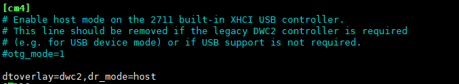
The USB port is disabled by default on the CM4 to save power. If you need to start, you need to add the following to the config.txt file:
dtoverlay=dwc2,dr_mode=host
After restarting
If you use the latest Raspberry Pi OS (image after October 30, 2021) USB2.0 is OTG mode by default, CM4 will report an error:
config failed, hub doesn't have any ports! (err -19)
However, USB can still be used. If you want to remove this error, remove otg_mode=1 in [cm4] of config.txt, and add dtoverlay=dwc2, dr_mode=host (USB cannot be recognized without adding it).