- sales/support
Google Chat:---
- sales
+86-0755-88291180
- sales01
sales@spotpear.com
- sales02
dragon_manager@163.com
- support
tech-support@spotpear.com
- CEO-Complaints
zhoujie@spotpear.com
- Only Tech-Support
WhatsApp:13246739196
- Purchase/Shipping/Refund
WhatsApp:13424403025
Raspberry Pi High-Precision AD HAT User Guide
Overview
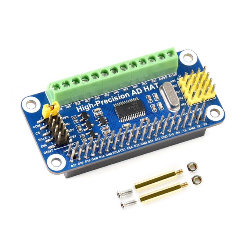
High-Precision AD HAT For Raspberry Pi, ADS1263 10-Ch 32-Bit ADC
Specification
- Resolution(Bits): 32
- Input channels: 10
- Sample rate(MAX): 38kSPS
- PGA Magnification(MAX): 32
- BUS: SPI
- Structure: Delta-Sigma
- Input type: differential, single-end
- Reference voltage: internal, external
- Input voltage range (MAX): 2.5V,5V
- Input voltage range(MIN):-2.5V, 0V
Fatures
- Adopts ADS1263 chip, low noise, low-temperature drift, 10-ch 32-bit high precision ADC (5-ch differential input), 38.4kSPS Max sampling rate
- with embedded 24-bit auxiliary ADC, internal ADC test signal, IDAC, 2.5V internal reference voltage, 8x multiplexing GPIO, PGA (32 times Max)
- Onboard AD header input, compatible with Waveshare sensor pinout, for connecting sorts of sensor modules
- Onboard AD screw terminal input, allows connecting analog signal and analog power supply, general-purpose interface
- Onboard control header, make it easy to control the module by other hosts in addition to Raspberry Pi
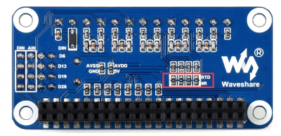
- Three-wire RTD (resistor temperature detector) circuit, enabled by soldering 0R resistor
Pinout
| PIN | Raspberry Pi(BCM) | Raspberry Pi(WiringPi) | Description |
| DRDY | P17 | P0 | ADS1263 data output ready, low active |
| RESET | P18 | P1 | ADS1263 reset input |
| CS | P22 | P3 | ADS1263 chip select, low active |
| DIN | P10 | P12 | SPI data input |
| DOUT | P9 | P13 | SPI data output |
| SCK | P11 | P14 | SPI clock |
Hardware configuration
Configure single-end
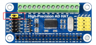
This board is set to the single-end mode by default. That is AVDD is connected to 5V, AVSS is connected to GND, and COM is connected to GND and set as negative end input.
You can connect the GND (or COM) and any IN pin to the target device for measuring.
Configure differential
If you want to measure a differential signal, you need to configure the board:
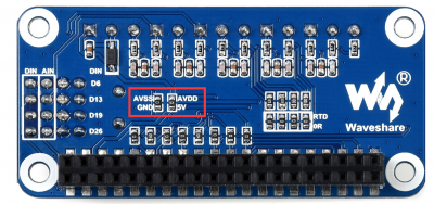
- Remove the 0ohm resistors of ACSS-GND, AVDD-5V which are on the backside. Remove the jumper of COM-GND.
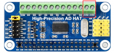
- Power the AVSS(-2.5V) and AVDD(+2.5V) pin from the terminal.
- Modify the codes and connect IN0&IN1 or other pins to measure differential signals.
Configure RTD
If you need to use the RTD function, please configure it as below:
- Solder four 0ohm resistors on the "RTD 0R" pads which is on the backside.
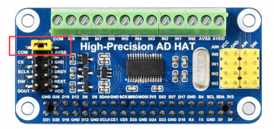
- Remove the jumpers of COM-GND
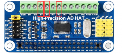
- Connect the positive end of the three-wire RTD module to IN7 and the less two to IN6 and IN4.
- Modify the codes
Communication protocol
SPI Protocol
The AD HAT uses an SPI interface, for more information about the protocol, you can refer to datasheet Page 11-12
SPI timing: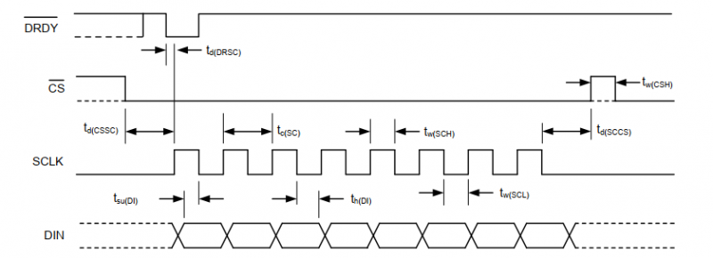
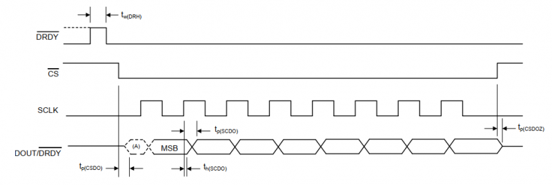
CS is chip select. The chip is active when the cs is low;
SCLK is the clock pin of SPI;
DIN is the data input pin, that is MOSI, master output, and slave input;
DOUT is the data output pin, that is MISO, master input, and slave output;
DRDY is the data ready output pin, when the data of ADC1 is ready to output, it is low.
SPI communication has data transfer timing, which is combined by CPHA and CPOL.
- CPOL determines the level of the serial synchronous clock at the idle state. When CPOL = 0, the level is Low. However, CPOL has little effect on the transmission.
- CPHA determines whether data is collected at the first clock edge or at the second clock edge of the serial synchronous clock; when CPHL = 0, data is collected at the first clock edge.
There are 4 SPI communication modes. SPI0 is commonly used, in which CPHL = 0, CPOL = 0.
As you can see from the figure above, data transmission starts at the first falling edge of SCLK, and 8 bits of data are transferred in one clock cycle. Here, SPI0 is in used, and data is transferred by bits, MSB first.