- sales/support
Google Chat:---
- sales
+86-0755-88291180
- sales01
sales@spotpear.com
- sales02
dragon_manager@163.com
- support
tech-support@spotpear.com
- CEO-Complaints
zhoujie@spotpear.com
- Only Tech-Support
WhatsApp:13246739196
- Purchase/Shipping/Refund
WhatsApp:13424403025
- HOME
- >
- ARTICLES
- >
- Common Moudle
- >
- UART Module
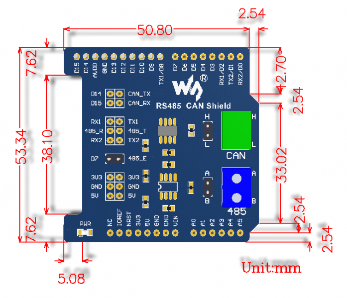
RS485 CAN Shield User Guide
Introduction
RS485 CAN Shield Designed for NUCLEO/XNUCLEO
How to use
Preparations
Two RS485 CAN Shield
Two STM32 development board, we use Waveshare Xnucleo-F103RB board (with STM32F103R chip) in this manual.
Some jumper wire.
Description of Jumper settings on Xnucleo
- D14 (PB_9) and D15 (PB_8) are CAN's sending and receiving port respectively as default.
- Note: please remap PB_9 and PB_8 to the function of STM32 CAN1 by modifying the program: GPIO_PinRemapConfig(GPIO_Remap1_CAN1, ENABLE);
- D7(PA_8) is for RS485 sending or receiving enable. High level is for sending, low level is for receiving.
- D8(PA_9), D2(PA_10) are the sending and receiving port of UART1. D0(PA_2), D1(PA_3) are the sending and receiving port of UART2. You can choose UART1 or UART2 for RS485 transceiver port by setting jumper 485 RXD/TXD JMP.
- Note: PA_2 and PA_3 of Xnucleo are Serial to USB ports as default. If you want use D0 and D1 as RS485 serial port, the jumper JP4 should be set: connect pin 1 and pin 3, connect pin 2 and pin 4.
- Communication between two boards: connect the CANH and CANL to another one’s CANH and CANL of the CAN port separately. Connect the A and B to another one’s A and B of the RS485 port separately.
Working principle
The demo program, divided into sending and receiving program, is based on mbed frame + STM32 library.
CAN
The CAN driver is written based on STM32 library, packaged into the two file CAN.cpp and CAN.h.
At the beginning of the program, function CAN_Config() is called to initiate related registers.
At the side of sending program, the message to be sent will be saved into the Mailbox TxMessage, then it will be sent by calling CAN_Transmit(CAN1, &TxMessage).
At the side of receiving program, the message received will be saved into the Mailbox RxMessage by calling CAN_Receive(CAN1, CAN_FIFO0, &RxMessage).
RS485
The sending side program sets RS485_E to high level, which will make RS485 into sending status. Messages will be sent by function RS485.printf, through RS485 serial port.
The receiving side program enables reception interruption, and sets RS485_E to low level, which will set RS485 to receiving status. Then, RX interrupt handler will scan received message via RS485.scanf.
Connection:
- D14 and D15 are CAN's sending and receiving port respectively as default.
- D8(PA_9), D2(PA_10) are the sending and receiving port of RS485.
- D7(PA_8) is for RS485 sending or receiving enable. High level is for sending, low level is for receiving.
- Message is sent to serial port of PC through D0 and D1.
- The CANH and CNAL of one CAN port should be connected to another’s CANH and CANL port, and the A and B port of one RS485 should be connected to another’s A and B.
Sending side program description
CAN: After related registers are initiated. the message to be sent will be saved into the Mailbox, and then it will be sent by driver functions.
RS485: Set RS485_E to high level, which will make RS485 into sending status. Messages will be sent through RS485 serial port.
#include "mbed.h"
#include "CAN.h"

Serial pc(D1,D0);                           //serial print message
Serial RS485(D8, D2);                       //RS485_TX RS485_RX
DigitalOut RS485_E(D7);                     //RS485_E

CanTxMsg TxMessage;
uint8_t TransmitMailbox = 0;
int i =0,j=0;

int main() {
        CAN_Config();                       //CAN initiation
        RS485_E = 1;                        //enable RS485 sending status

        /* TxMessage */                     //Setting message of Txmessage
        TxMessage.StdId = 0x10;
        TxMessage.ExtId = 0x1234;
        TxMessage.RTR=CAN_RTR_DATA;
        TxMessage.IDE=CAN_ID_STD;
        TxMessage.DLC=8;
        TxMessage.Data[0] = 'C';
        TxMessage.Data[1] = 'A';
        TxMessage.Data[2] = 'N';
        TxMessage.Data[3] = ' ';
        TxMessage.Data[4] = 'T';
        TxMessage.Data[5] = 'e';
        TxMessage.Data[6] = 's';
        TxMessage.Data[7] = 't';

        pc.printf( "**** This is a RS485_CAN_Shield Send test program ****\r\n");

        while(1) {
                RS485.printf("ncounter=%d ",j);                                         //RS485 sending
                wait(1);
                TransmitMailbox = CAN_Transmit(CAN1, &TxMessage);                       //CAN sending

                i = 0;
                while((CAN_TransmitStatus(CAN1, TransmitMailbox) != CANTXOK) && (i != 0xFFF)){
                        i++;
                }
                if(i == 0xFFF){
                        pc.printf("\r\can send fail\r\n");                              //Send Timeout, fail
                }
                else{
                        pc.printf("\r\nCAN send TxMessage successfully \r\n");          //Send successfully
                }
                pc.printf("\r\nRS485 send: counter=%d\r\n",j++);                        //Print message
                pc.printf("The CAN TxMsg: %s\r\n",TxMessage.Data);
                wait(1);
        }
}
Receiving side program description
CAN: After related registers are initiated. The receiving side will check if FIFO data exist. If yes, the received message will be saved in the mailbox RxMessage and printed.
RS485: Enable RS485 reception interruption and set RS485_E to low for setting RS485 to receving status. Then, interrupt service routine will scan received message via RS485.scanf.
#include "mbed.h"
#include "CAN.h"

Serial pc(D1,D0);                                                       //serial print message
Serial RS485(D8, D2);                                                   //RS485_TX RS485_RX
DigitalOut RS485_E(D7);                                                 //RS485_E

CanRxMsg RxMessage;                                                     //RxMessage
char s[1024];

void callback()                                                         //RS485 RX interrupt handler
{                                                                       //Note: you need to actually read from the serial to clear the RX interrupt
        RS485.scanf("%s",s);                                            //Save received messages
        pc.printf("\r\nRS485 Receive:%s \r\n",s);                       //Print Received messages
}

int main() {

        CAN_Config();                                                   //CAN initiation
        RS485.attach(&callback);                                        //Open RS485 reception interruption
        RS485_E = 0;                                                    //Enable receiving status
        pc.printf( "**** This is a can receive test program ****\r\n");
        while(1) {
                while(CAN_MessagePending(CAN1, CAN_FIFO0) < 1)          // Message waiting
                {
                }
                CAN_Receive(CAN1, CAN_FIFO0, &RxMessage);               //CAN data reception
                pc.printf("The CAN RxMsg: %s\r\n",RxMessage.Data);      //Print received messages
        }
}
Operating phenomenon
The serial port of sending side will print:
**** This is a RS485_CAN_Shield Send test program ****

CAN send TxMessage successfully

RS485 send: counter=0
The CAN TxMsg: CAN Test

CAN send TxMessage successfully

RS485 send: counter=1
The CAN TxMsg: CAN Test

CAN send TxMessage successfully

RS485 send: counter=2
The CAN TxMsg: CAN Test
The serial port of receiving side will print:
**** This is a can receive test program ****

RS485 Receive:ncounter=0
The CAN RxMsg: CAN Test

RS485 Receive:ncounter=1
The CAN RxMsg: CAN Test

RS485 Receive:ncounter=2
The CAN RxMsg: CAN Test

RS485 Receive:ncounter=3
The CAN RxMsg: CAN Test