


- sales/support
Google Chat:---
- sales
+86-0755-88291180
- sales01
sales@spotpear.com
- sales02
dragon_manager@163.com
- support
tech-support@spotpear.com
- CEO-Complaints
zhoujie@spotpear.com
- Only Tech-Support
WhatsApp:13246739196
- Purchase/Shipping/Refund
WhatsApp:13424403025
RPi Tutorial Series: Infrared Remote Control User Guide
In this lesson, you will learn how to control your Raspberry Pi using a IR controller. You may have learned how to add a device to the device tree in Linux, and we are also going to add an IR receiver to the device tree.
sudo vi /boot/config.txt
and append
dtoverlay=lirc-rpi
This causes the file /boot/overlays/lirc-rpi-overlay.dtb to be loaded. By default it will use GPIOs 17 (out) and 18 (in). (Quote from /boot/overlay/README) Then please place the output pin of an IR receiver to the 18 pin (BCM numbering, use this command to check: gpio readall). Or if you are using the expension board Pioneer600, the output pin of IR receiver is connected to the 18 pin (input pin on Pi) by default. You can specify a pin on your Pi as IR input using DT (Device Tree) parameters, just append gpio_in_pin, followed by the pin number, to the dtoverlay=lirc-rpi line:
dtoverlay=lirc-rpi,gpio_in_pin=18
Just an example, gpio_in_pin=18 is a verbose declaration because the GPIO 18 has set to input by default already. Then install the lirc software:
sudo apt-get install lirc
and you will find the lirc_rpi device with lsmod command.
lsmod | grep lirc
You get:
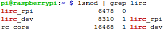
If everything works, you can use the mode2 command to check the IR waveform:
sudo mode2 -d /dev/lirc0
Press the button on a remote controller aiming the IR receiver, and a certain pulse signals will be printed in the terminal, like:
space ...
pulse ...
...
The pulse signal from the infrared remote controller complies with the NEC standard. The infrared remote receiver outputs the pulse to the Pin 18 of the BCM after relative signal received. Then, the Raspberry Pi reads the pulse from the Pin 18 and decodes it.
Infrared NEC protocol coding description
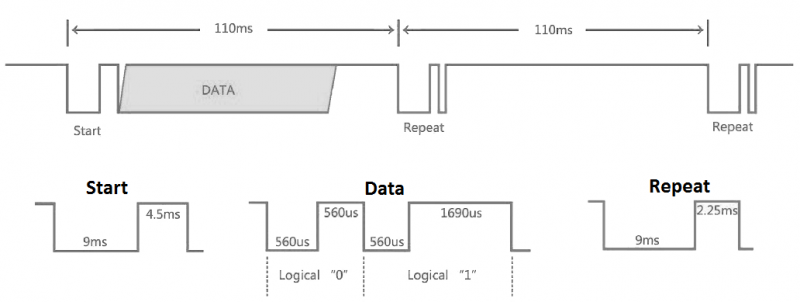
Data format: Address, ~(Address), Command, ~(Command)
~(Address): bit-wise complement of Address. ~(Command): bit-wise complement of Command
Both address and command are in a format of 8 bits, so a complete signal is in 32 bits.
Start signal is composed with a 9 ms leading space and a 4.5 ms pulse and it is followed by 4 bytes, they are
- an 8-bit ADDRESS for receiving
- an 8-bit logical inverse of the ADDRESS
- an 8-bit COMMAND
- an 8-bit logical inverse of the COMMAND
The Logic '0' and '1' are expressed as:
- Logic '0' == 0.56 ms LOW and 0.56 ms HIGH
- Logic '1' == 0.56 ms LOW and 0.169 ms HIGH
The controller sends data only once and then only repeat pulse will be sent. Therefore, if you want to send data again, you should release the button and press it again, rather than keep pressing the button.
Demo Code
- These examples require a certain library, see: Libraries Installation for RPi
Python
#!/usr/bin/python
# -*- coding:utf-8 -*-
import RPi.GPIO as GPIO
import time
ERROR = 0xFE
PIN = 18
GPIO.setmode(GPIO.BCM)
GPIO.setup(PIN, GPIO.IN, GPIO.PUD_UP)

def getKey():
    byte = [0, 0, 0, 0];
    if IRStart() == False:
        time.sleep(0.11);        # One message frame lasts 108 ms.
        return ERROR;
    else:
        for i in range(0, 4):
                byte[i] = getByte();
        # Start signal is followed by 4 bytes:
        # byte[0] is an 8-bit ADDRESS for receiving
        # byte[1] is an 8-bit logical inverse of the ADDRESS
        # byte[2] is an 8-bit COMMAND
        # byte[3] is an 8-bit logical inverse of the COMMAND
        if byte[0] + byte[1] == 0xff and byte[2] + byte[3] == 0xff:
            return byte[2];
        else:
            return ERROR;
def IRStart():
    timeFallingEdge = [0, 0];
    timeRisingEdge = 0;
    timeSpan = [0, 0];
    GPIO.wait_for_edge(PIN, GPIO.FALLING);
    timeFallingEdge[0] = time.time();
    GPIO.wait_for_edge(PIN, GPIO.RISING);
    timeRisingEdge = time.time();
    GPIO.wait_for_edge(PIN, GPIO.FALLING);
    timeFallingEdge[1] = time.time();
    timeSpan[0] = timeRisingEdge - timeFallingEdge[0];
    timeSpan[1] = timeFallingEdge[1] - timeRisingEdge;
    # Start signal is composed with a 9 ms leading space and a 4.5 ms pulse.
    if timeSpan[0] > 0.0085 and \
       timeSpan[0] < 0.0095 and \
       timeSpan[1] > 0.004 and \
       timeSpan[1] < 0.005:
        return True;
    else:
        return False;
def getByte():
    byte = 0;
    timeRisingEdge = 0;
    timeFallingEdge = 0;
    timeSpan = 0;
    # Logic '0' == 0.56 ms LOW and 0.56 ms HIGH
    # Logic '1' == 0.56 ms LOW and 0.169 ms HIGH
    for i in range(0, 8):
        GPIO.wait_for_edge(PIN, GPIO.RISING);
        timeRisingEdge = time.time();
        GPIO.wait_for_edge(PIN, GPIO.FALLING);
        timeFallingEdge = time.time();
        timeSpan = timeFallingEdge - timeRisingEdge;
        if timeSpan > 0.0016 and timeSpan < 0.0018:
            byte |= 1 << i;
    return byte;
print('IRM Test Start ...')
try:
    while True:
        key = getKey();
        if(key != ERROR):
            print("Get the key: 0x%02x" %key)
except KeyboardInterrupt:
    GPIO.cleanup();
Save the code as "irm.py" and run with:
sudo python irm.py