


- sales/support
Google Chat:---
- sales
+86-0755-88291180
- sales01
sales@spotpear.com
- sales02
dragon_manager@163.com
- support
tech-support@spotpear.com
- CEO-Complaints
zhoujie@spotpear.com
- Only Tech-Support
WhatsApp:13246739196
- Purchase/Shipping/Refund
WhatsApp:13424403025
DDSM400 User Guide
Overview
Introduction
The DDSM400 direct drive servo motor is based on an integrated development concept, combining an outer rotor brushless motor, encoder, and servo drive into a highly reliable permanent magnet synchronous motor. It features a compact design, easy installation, and stable operation. Its small size and high speed are particularly suitable for the following direct drive applications: driving wheels for small AGVs, driving wheels for balance vehicles, and high-end robotics projects for developing vehicle platforms.
Through the optimization of the number of pole slots, geometry, air gap, permanent magnet materials, etc., the motor is guaranteed to have a speed of up to 400±20RPM in the no-load state, and can rotate at a rated speed of 100RPM combined with a rated torque of 0.15Nm, which can be used for robot projects that require high-speed rotation and low torque requirements, providing users with high-performance direct drive application solutions.
The motor is compatible with a driver that utilizes the Field Oriented Control (FOC) algorithm, combined with high-precision sensors integrated into the motor, achieving precise control over the motor and better noise reduction. The driver has a complete and reliable motor OBD (On-board diagnostics) monitoring mechanism and protection function to ensure the safe and reliable operation of the motor.
At the same time, we provide an open source four-wheel drive off-road vehicle structure model for this model of direct drive servo motor, you can download the model and engineering files of the open source structure in the bottom "Resources" - "Open Source Structure".
Features
- Ultra-low noise
- High precision and zero-backlash
- Fast response, direct drive without delay
- Integrated motor and driver, compact structure and high integration
- Supports LIN bus communication method
- Motor feedback information such as position, speed, current, error code can be obtained through communication
- Supports Hall position detection, over-current protection and other functions
- Supports electric brakes
- No drive mechanical friction, drive efficiency close to 99.99%
Specifications
| DDSM400 Hub Motor | |||
|---|---|---|---|
| Rated voltage | 25.2V DC | Operating voltage | 9~28V DC |
| Rated speed | 100rpm | No-load speed | 400±20rpm |
| Rated current | 0.24±0.07A | No-load current | 0.25A |
| Stall current | 1.0±0.2A | Ambient temperature | -5~40℃ |
| Rated torque | 0.15Nm/V | Stall torque | 0.3Nm/A |
| Encoder resolution | 4096 | Relative accuracy | 1024 |
| Total weight | 236g | Single wheel load | 4kg |
| Speed constant | 15.9rpm/V | Noise level | ≤45dB(A) |
Precautions
1. Confirm whether the operating voltage is within the specified voltage range as listed in Specifications.
2. Ensure that the motor is used within the specified ambient temperature range (-5°C~40°C).
3. Please avoid soaking the motor in water, otherwise it may cause abnormal operation or damage to the motor.
4. Please ensure that the connections are correct and secure before use, to avoid any issues with poor contact.
5. Please refer to the installation instructions before using the motor to ensure that the motor is installed correctly and steadily.
6. Please refer to the installation instructions before using the motor to ensure that the external output part of the motor is installed correctly and steadily.
7. Please avoid damaging the cables when using, as this may lead to abnormal operation or damage to the motor.
8. Do not touch the rotating part of the motor when using to avoid injury.
9. When the motor produces a large torque output, it may become hot. Do not touch the motor to avoid burns.
10. Do not disassemble the motor without permission, otherwise it may cause abnormal operation or damage to the motor, and may bring potential safety hazards.
Motor Interface and Wiring Description
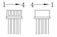
- Interface type: PH2.0*4P
- Wiring harness number: red and black power cable – 26AWG; white and yellow signal cable – 28AWG
| Cable number | Name | Color | Type | Description |
|---|---|---|---|---|
| 1 | Reserved | Yellow | Signal cable | Reserved |
| 2 | LIN | White | Signal cable | Single-cable, half-duplex serial port |
| 3 | GND | Black | Power Negative | - |
| 4 | VCC | Red | Power Positive | - |
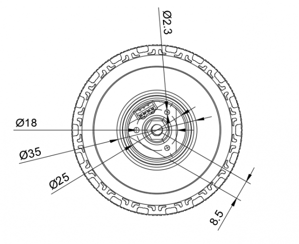
Installation Guide
Please refer to the size and location of the motor mounting hole to install the motor to your project. You can also use our suspension component UGV Suspension (B) to install a hub motor.
- The size of the mounting hole at the mounting end of the motor is M2.5, the depth is 6mm, and the centers of the mounting holes are evenly distributed on a circle with a diameter of 18mm, please select the appropriate screws for installation.
- The mounting end of the motor is made of plastic, so it can be directly screwed in with screws.
Product Use
Simple Usage
Hardware connection
We currently do not have a matching driver board to drive this motor. If you wish to use a hub motor in your project, you can solve the control circuit based on the following schematic diagram.
Single-wire serial transceiver: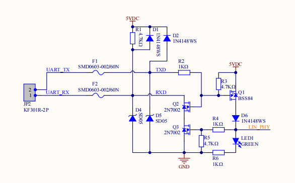
If you already have a LIN to TTL module, you might need another USB to TTL module. You can connect it according to the following wiring instructions:
- Connect the RX of the LIN to TTL module with the RX of the USB to TTL module;
- Connect the TX of the LIN to TTL module with the TX of the USB to TTL module;
- Connect the GND of the LIN to TTL module to the negative terminal of the DC power supply;
- Connect the VCC of the LIN to TTL module to the positive terminal of the DC power supply;
- Connect the GND of the USB to TTL module to the negative terminal of the DC power supply.
Serial port debugging assistant
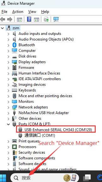
Serial port device check
Ensure that you have correctly connected according to the content in the above hardware connection, and after plugging the USB to TTL module into the computer, search for "Device Manager" in the left lower corner of Windows to check if the serial port is connected properly.
Drive motor
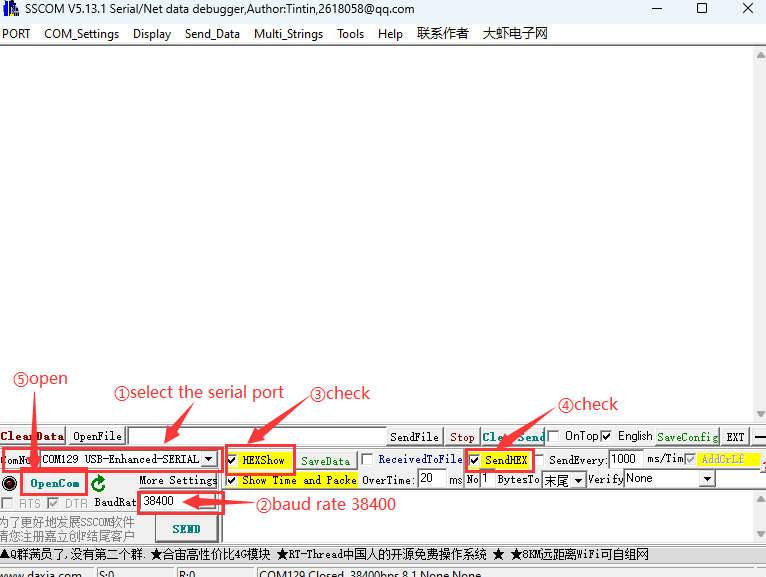
Here introduces the use of a simple serial port debugging assistant to control the hub motor. Download Serial Port Debugger Assistant, after downloading, open "cktszsss32.exe", select the correct serial port, choose a baud rate of 38400, check "HEX Display" and "HEX Send", click "Open Serial Port", as shown in the following image.
After powering on the motor, it is in a disabled state. It needs to be enabled first. After enabling, it defaults to the current loop mode. According to the communication protocol, the motor mode can be switched to the speed loop for control, as detailed in the Motor Mode Switching section of the communication protocol. The default ID of the factory motor is 1 or 2.
Example 1: To make the ID1 motor rotate at 30RPM, you can send the following command in the serial port assistant:
- Enable command: 01 A0 08 00 00 00 00 00 00 6F
- Switch to speed loop command: 01 A0 02 00 00 00 00 00 00 E4
- Given a 30RPM RPM command: 01 64 01 2C 00 00 00 00 00 A6
- Given a 0RPM RPM command: 01 64 00 00 00 00 00 00 00 50
Example 2: To make the ID2 motor rotate at 30RPM, you can send the following command in the serial port assistant:
- Enable command: 02 A0 08 00 00 00 00 00 00 9A
- Switch to speed loop command: 02 A0 02 00 00 00 00 00 00 11
- Given a 30RPM RPM command: 02 64 01 2C 00 00 00 00 00 53
- Given a 0RPM RPM command: 02 64 00 00 00 00 00 00 00 A5
Common instruction set
Motor mode switching
01 A0 00 00 00 00 00 00 00 9E (Open loop)
01 A0 01 00 00 00 00 00 00 A3 (Current loop)
01 A0 02 00 00 00 00 00 00 E4 (Speed loop)
01 A0 08 00 00 00 00 00 00 E4 (Motor enabled)
01 A0 09 00 00 00 00 00 00 E4 (Motor disabled)
If the motor ID changes, the CRC8 value needs to be recalculated, and the instruction also changes
Open loop command
01 64 F8 30 00 00 00 00 00 08 (-2000)
01 64 EC 78 00 00 00 00 00 D3 (-5000)
01 64 D8 F0 00 00 00 00 00 78 (-10000)
01 64 00 00 00 00 00 00 00 50 (0)
01 64 07 D0 00 00 00 00 00 27 (2000)
01 64 13 88 00 00 00 00 00 A7 (5000)
01 64 27 10 00 00 00 00 00 57 (10000)
Current loop command
Given value range: -32767~32767; corresponding range is -4A~4A
01 64 F8 30 00 00 00 00 00 08 (-2000)
01 64 EC 78 00 00 00 00 00 D3 (-5000)
01 64 D8 F0 00 00 00 00 00 78 (-10000)
01 64 00 00 00 00 00 00 00 50 (0)
01 64 07 D0 00 00 00 00 00 27 (2000)
01 64 13 88 00 00 00 00 00 A7 (5000)
01 64 27 10 00 00 00 00 00 57 (10000)
Speed loop command
Given value range: -380~380 rpm
01 64 FE 0C 00 00 00 00 00 16 (-50rpm)
01 64 FC 18 00 00 00 00 00 E8 (-100rpm)
01 64 00 00 00 00 00 00 00 50 (0rpm)
01 64 01 F4 00 00 00 00 00 C3 (50rpm)
01 64 03 E8 00 00 00 00 00 9F (100rpm)
Brake command
Valid in speed loop mode:
01 64 00 00 00 00 00 FF 00 D1 (Motor 1)
02 64 00 00 00 00 00 FF 00 24 (Motor 2)
Obtain motor feedback
- Obtain mode feedback
01 75 00 00 00 00 00 00 00 47 (Motor 1)
02 75 00 00 00 00 00 00 00 B2 (Motor 2)
- Obtain other feedback
01 74 00 00 00 00 00 00 00 04 (Motor 1)
02 74 00 00 00 00 00 00 00 F1
Communication Protocol
Communication Setting
- Baud rate: 38400; Data bit: 8bit; Stop bit: 1bit; Parity bit: None
- Data length: 10 bytes
- Response format: one question, one answer
- Rate: up to 250Hz
- In current loop mode: -32767~32767 corresponds to -4A~4A, the data type is signed 16-bit;
- In speed loop mode: -3800~3800 corresponds to -380rpm~380rpm, with a unit of 0.1rpm and the data type is signed 16-bit;
- In position loop mode: 0~32767 corresponds to 0 °~360 °, the data type is unsigned 16-bit;
Note: The baud rate cannot be modified by command
Operation steps:
       ①Set the motor ID (power-off save)

       ②Send the enable command, default current loop when enabled

       ③Send the given value
CRC8 checksum calculation method
- CRC8 value: The value after performing CRC8 checksum on the values DATA[0] to DATA[8].
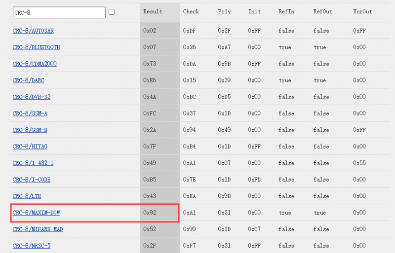
- CRC algorithm: CRC-8/MAXIM
- Polynomial: x8 + x5 + x4 +1
In the verification product stage, the check digit can be calculated through this website: https://crccalc.com/
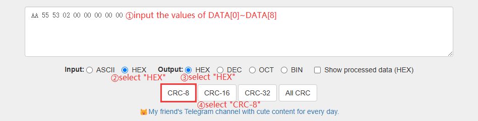
Example: Set the factory motor ID to 2:
Input the values of DATA[0]~DATA[8] into the input box on the above website. After inputting, select "HEX Input" and "HEX Output", choose "CRC-8", and you will see the numbers change below. Note that the result of CRC-8/MAXIM-DOW is 0x92. The command to set the motor ID to 2 is: AA 55 53 02 00 00 00 00 00 92
Protocol 1: Drive the motor to rotate
| Send to the motor: | ||||||||||
| Data domain | DATA[0] | DATA[1] | DATA[2] | DATA[3] | DATA[4] | DATA[5] | DATA[6] | DATA[7] | DATA[8] | DATA[9] |
|---|---|---|---|---|---|---|---|---|---|---|
| Content | ID | 0x64 | Given high 8 bits of speed/position/current | Given low 8 bits of speed/position/current | 0 | 0 | Acceleration time | Brake | 0 | CRC8 |
| Motor feedback: | ||||||||||
| Data domain | DATA[0] | DATA[1] | DATA[2] | DATA[3] | DATA[4] | DATA[5] | DATA[6] | DATA[7] | DATA[8] | DATA[9] |
| Content | ID | 0x65 | High 8 bits of speed | Low 8 bits of speed | High 8 bits of current | Low 8 bits of current | Acceleration time | Temperature | Fault code | CRC8 |
- Acceleration time: Valid in speed loop mode, the acceleration time per 1rpm is 1ms. When set to 1, the acceleration time per 1rpm is 1ms. When set to 10, the acceleration time per 1rpm is 10*1ms=10ms. When set to 0, the default value is 1, and the acceleration time per 1rpm is 1ms.
- Brake: Other values of 0XFF do not brake, and are valid in speed loop mode.
Protocol 2: Obtain other feedback
| Send to the motor: | ||||||||||
| Data domain | DATA[0] | DATA[1] | DATA[2] | DATA[3] | DATA[4] | DATA[5] | DATA[6] | DATA[7] | DATA[8] | DATA[9] |
|---|---|---|---|---|---|---|---|---|---|---|
| Content | ID | 0x74 | 0 | 0 | 0 | 0 | 0 | 0 | 0 | CRC8 |
| Motor feedback: | ||||||||||
| Data domain | DATA[0] | DATA[1] | DATA[2] | DATA[3] | DATA[4] | DATA[5] | DATA[6] | DATA[7] | DATA[8] | DATA[9] |
| Content | ID | 0x75 | High 8 bits of mileage laps | Next high 8 digits of mileage laps | Next low 8 digits of mileage laps | Low 8 bits of mileage laps | High 8 bits of position | Low 8 bits of position | Fault code | CRC8 |
- Mileage laps: Lap range -2147483467 to 2147483467, will be cleared to 0 when re-powered
- Position value: 0~32767 corresponds to 0~360°
- Fault codes:
| Fault value | BIT7 | BIT6 | BIT5 | BIT4 | BIT3 | BIT2 | BIT1 | BIT0 |
|---|---|---|---|---|---|---|---|---|
| Content | Reserved | Overvoltage and undervoltage faults | Disconnection fault | Overtemperature fault | Stall fault | Reserved | Overcurrent fault | Hall fault |
For example, the fault code is 0x02, which means 0b 0000010, indicating an overcurrent fault has occurred.
Protocol 3: Motor mode switch transmission protocol
| Send to the motor: | ||||||||||
| Data domain | DATA[0] | DATA[1] | DATA[2] | DATA[3] | DATA[4] | DATA[5] | DATA[6] | DATA[7] | DATA[8] | DATA[9] |
|---|---|---|---|---|---|---|---|---|---|---|
| Content | ID | 0xA0 | Mode value | 0 | 0 | 0 | 0 | 0 | 0 | CRC8 |
| Motor feedback: | ||||||||||
| Data domain | DATA[0] | DATA[1] | DATA[2] | DATA[3] | DATA[4] | DATA[5] | DATA[6] | DATA[7] | DATA[8] | DATA[9] |
| Content | ID | 0xA1 | Mode value | 0 | 0 | 0 | 0 | 0 | 0 | CRC8 |
- Mode value:
- 0x00: Set to open loop
- 0x01: Set to current loop
- 0x02: Set to speed loop
- 0x03: Set to position loop
- 0x08: Motor enabled
- 0x09: Motor disabled
Protocol 4: Motor ID set transmission protocol
| Send to the motor: | ||||||||||
| Data domain | DATA[0] | DATA[1] | DATA[2] | DATA[3] | DATA[4] | DATA[5] | DATA[6] | DATA[7] | DATA[8] | DATA[9] |
|---|---|---|---|---|---|---|---|---|---|---|
| Content | 0xAA | 0x55 | 0x53 | ID | 0 | 0 | 0 | 0 | 0 | CRC8 |
| Motor feedback: | ||||||||||
| Data domain | DATA[0] | DATA[1] | DATA[2] | DATA[3] | DATA[4] | DATA[5] | DATA[6] | DATA[7] | DATA[8] | DATA[9] |
| Content | ID | 0x65 | 0 | 0 | 0 | 0 | 0 | 0 | 0 | CRC8 |
Note: When setting the ID, please ensure that only one motor is powered on. It is only allowed to be set once each time it is powered on. The motor is set after receiving 5 ID setting instructions.
Protocol 5: Obtain mode feedback
| Send to the motor: | ||||||||||
| Data domain | DATA[0] | DATA[1] | DATA[2] | DATA[3] | DATA[4] | DATA[5] | DATA[6] | DATA[7] | DATA[8] | DATA[9] |
|---|---|---|---|---|---|---|---|---|---|---|
| Content | ID | 0x75 | 0 | 0 | 0 | 0 | 0 | 0 | 0 | CRC8 |
| Motor feedback: | ||||||||||
| Data domain | DATA[0] | DATA[1] | DATA[2] | DATA[3] | DATA[4] | DATA[5] | DATA[6] | DATA[7] | DATA[8] | DATA[9] |
| Content | ID | 0x76 | Mode value | 0 | 0 | 0 | 0 | 0 | 0 | CRC8 |
Mode value:
- 0x00: Open loop
- 0x01: Current loop
- 0x02: Speed loop
- 0x03: Position loop
Protection Rules
1. Bus overcurrent protection threshold:
 1) 1.5A, the shutdown protection will be triggered after continuous overcurrent for 8S, and it will be automatically
released after 5S.
 2) 2.5A, the shutdown protection will be triggered after continuous overcurrent for 5S, and it will be automatically
released after 5S.
 3) 4A, the shutdown protection will be triggered after continuous overcurrent for 1S, and it will be automatically
released after 5S.
2. Motor overtemperature protection threshold:
 1) 80℃, the shutdown protection will be triggered when the temperature is higher than 80°C, and it will be
automatically released when the temperature drops below this threshold by 5℃;
 2) -25℃, the shutdown protection will be triggered when the temperature is below -25 ℃, and it will be automatically
 released when the temperature is 5°C above the threshold;
3. Stall prevention: the protection will be triggered after the stall duration exceeds 5S, and it will be automatically released after 5S (the speed loop is effective)
4. Overvoltage protection threshold:
 1) 28V, the shutdown protection will be triggered when the voltage is higher than 28V, and the protection will be
automatically released when the voltage is 0.5V lower than the threshold;
 2) 9V, the shutdown protection will be triggered when the voltage is lower than 9V, and the protection will be
automatically released when the voltage is 0.5V higher than the threshold;
Resources
3D model
Open source structure
Serial port debugging assistant
Support
Monday-Friday (9:30-6:30) Saturday (9:30-5:30)
Email: services01@spotpear.com
[Tutorial Navigation]
- Overview
- Introduction
- Features
- Specifications
- Precautions
- Motor Interface and Wiring Description
- Installation Guide
- Product Use
- Simple Usage
- Communication Protocol
- Communication Setting
- CRC8 checksum calculation method
- Protocol 1: Drive the motor to rotate
- Protocol 2: Obtain other feedback
- Protocol 3: Motor mode switch transmission protocol
- Protocol 4: Motor ID set transmission protocol
- Protocol 5: Obtain mode feedback
- Protection Rules
- Resources
- Support