


- sales/support
Google Chat:---
- sales
+86-0755-88291180
- sales01
sales@spotpear.com
- sales02
dragon_manager@163.com
- support
tech-support@spotpear.com
- CEO-Complaints
zhoujie@spotpear.com
- Only Tech-Support
WhatsApp:13246739196
- Purchase/Shipping/Refund
WhatsApp:13424403025
- HOME
- >
- ARTICLES
- >
- LuckFox
- >
- LuckFox Pico
Luckfox Pico RV1103【Tutorial on how to use UART】
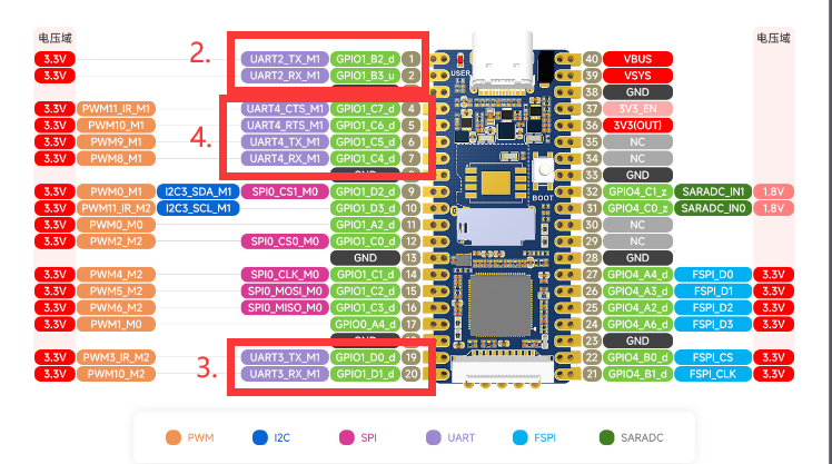
The LuckFox Pico has three serial ports: UART2, UART3, and UART4. Among them, UART2 is the debug port.
The LuckFox Pico Plus has four serial ports: UART2, UART3, UART4, and UART5. Among them, UART2 is the debug port.
】Performing serial port testing using the GPIO sysfs interface:
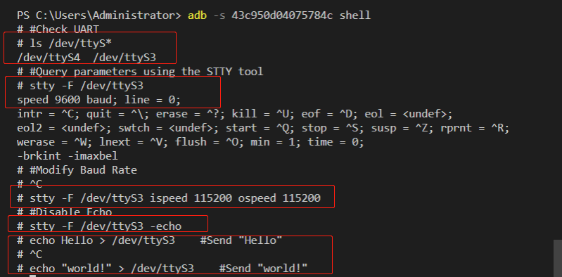
1] View serial port:
root@linaro-alip:/home/linaro# ls /dev/ttyS*
/dev/ttyS3 /dev/ttyS4
##The serial port devices here are UART3 and UART4
2] Use the “stty” tool to query the serial port communication parameters:
linaro@linaro-alip:~$ stty -F /dev/ttyS3
speed 9600 baud; line = 0;
-brkint -imaxbel
##The default baud rate is 9600
3] Modify the baud rate, where ispeed is the input rate and ospeed is the output rate:
stty -F /dev/ttyS3 ispeed 115200 ospeed 115200
4] Disable echo:
stty -F /dev/ttyS3 -echo
## Disabling echo refers to the situation where the characters entered in the terminal or serial communication are no longer displayed on the terminal.
5] Operation process screenshot:
】Communicating with a Windows host:
Connect one end of the serial port module to the computer, and the other end to the physical pins 18 (GND), 19 (UART7_TX), and 20 (UART7_RX) of the LuckFox Pico.
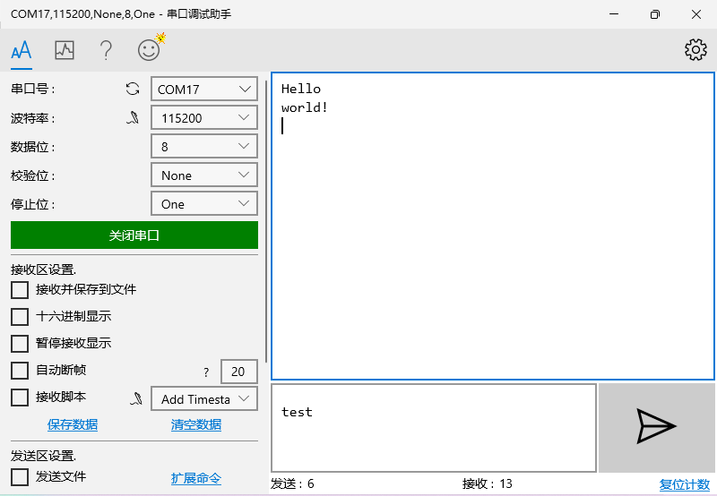
Download and open PuTTY (or any other serial port software), select the serial port, and set the baud rate (default is 9600, please adjust it according to your actual modified value).
Execute the following command on the terminal of the development board to write the strings “Hello” and “world!” to the terminal device file using the echo command:
echo Hello > /dev/ttyS3
echo "world !" > /dev/ttyS3
The serial port debugging assistant on Windows will receive the content:
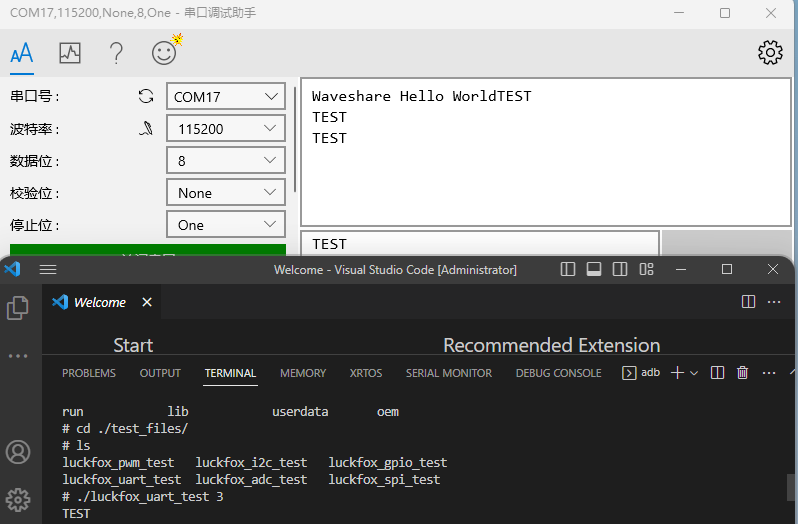
】Test the built-in sample program of the official SDK:
(The following operations need to be performed in the terminal of the Pico development board)
3] Run the test sample program:
chmod 777 ./luckfox_uart_test
## Grant executable permissions to the file
./luckfox_uart_test 3
##The parameter 3 in the example represents UART3.
4] Open the serial communication device to receive data:
TAG:
ESP32-S3 1.69inch LCD Display With QST Attitude Gyro Sensor QMI8658C For Arduino Python
RISC-V
800x480
Onboard ESP32-C6 Development Board
3.5inch RPi LCD (A) Manual Configuration
Sensor
Solar Charge Module
Raspberry Pi Thermal imaging camera
User Guide
Raspberry Pi Screen
Raspberry Pi Prism
RS232 to RJ45
Sipeed Tang Primer 25K GW5A RISCV FPGA Development Board Dock SDRAM GW5A-LV25MG121 Retro Game linux
Raspberry Pi 5 Case
USB to UART
ESP32 C6 Development board 1.9 inch LCD display 1.9inch Screen 172×320 With SD slot RGB LED QMI8658 6-Axis-Sensor ST7789 CST816
Milk-V Duo S 512MB SG2000 RISC-V
Raspberry Pi 5 PCIe To M.2 E KEY NGFF WIFI7 WIFI6 For BE200/AX210/AX200/RTL8822CE
Raspberry Pi 4/5 UPS Uninterruptible Power Supply HAT Lithium Battery Module
Raspberry Pi Pico Display
TAG:
Core2021 LoRa LR2021 HF LF SPI LoRaWAN For Sub-GHz and 2.4GHz
Raspberry Pi 5 inch DSI IPS LCD Display MIPI 800x480 Optional Touchscreen
Raspberry Pi RP2040
2.66inch E-Paper E-ink G Screen Display 360x184 Red/Yellow/Black/White SPI Communication SpotPear
Raspberry Pi 5inch DSI LCD B Display MIPI IPS 800x480 Capacitive TouchScreen
Raspberry Pi 10.1 inch DSI LCD TouchScreen Display 720x1280 RK3576 RK3506 ESP32-P4 Luckfox Lyra
Raspberry Pi 5 Model - 1GB RAM
ESP32 C6 AI 1.54inch Development Board 1.54 inch TouchScreen Display DeepSeek
Raspberry Pi 3b+ PoE
ESP32 GamePad Retro Game MP3 Player FC NES
Raspberry Pi 14-inch Type-C/HDMI 4K TouchScreen 3840×2160 14inch computer
ESP32 C3
ESP32 S3 Development Board 3.5 inch LCD Capacitive Touch Screen 3.5inch Display 320×480 N16R8
Raspberry Pi 5 Argon-NEO-M.2-NVME-PCIE-Expansion-Board Argon NEO 5 Case
Jetson Nano
CPU
EchoEar ESP32 S3 AI Development Board with 1.85-inch LCD Display Cute Cat Pet Chatting Robot N32R16
Industrial ESP32 S3 AI 7inch (C) Development Board 7 inch TouchScreen Display Sensor
Computer Monitor Display
Industrial UART Converter USB RS232/485 FT232RNL Compact Size