- sales/support
Google Chat:---
- sales
+86-0755-88291180
- sales01
sales@spotpear.com
- sales02
dragon_manager@163.com
- support
tech-support@spotpear.com
- CEO-Complaints
zhoujie@spotpear.com
- Only Tech-Support
WhatsApp:13246739196
- Purchase/Shipping/Refund
WhatsApp:13424403025
7-DSI-TOUCH-A User Guide
Features
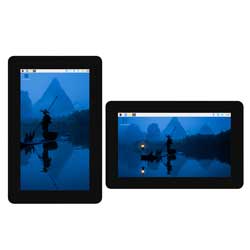
- 7inch DSI touch screen, ten-point capacitive touch control
- IPS display panel with hardware resolution of 720×1280
- Toughened glass capacitive touch panel, hardness up to 6H
- Optical bonding toughened glass panel, clearer picture quality
- Using AF anti-fingerprint process, not easy to get fingerprints and easy to clean
- Drive the LCD through the DSI interface, with a refresh rate of up to 60Hz
- Supports software control of backlight brightness
Electrical Specifications
| Parameters | Minimum Value | Standard Value | Maximum Value | Unit | Note |
| Input voltage | 4.75 | 5.00 | 5.30 | V | Note 1 |
| Input current | - | 0.5 | TBD | A | Note 2 |
| Operating temperature | 0 | 25 | 60 | ℃ | Note 3 |
| Storage temperature | -10 | 25 | 70 | ℃ | Note 3 |
•Note 1: Input voltages exceeding the maximum or improper operation may cause permanent damage to the device.
•Note 2: The input current needs to be ≥ 0.5A, otherwise it will cause the startup failure or display abnormality, and staying in an abnormal state for a long time may cause permanent damage to the device.
•Note 3: Please do not store the display panel in a high-temperature and high-humidity environment for a long time. The display panel should operate within its limits, otherwise it may be damaged.
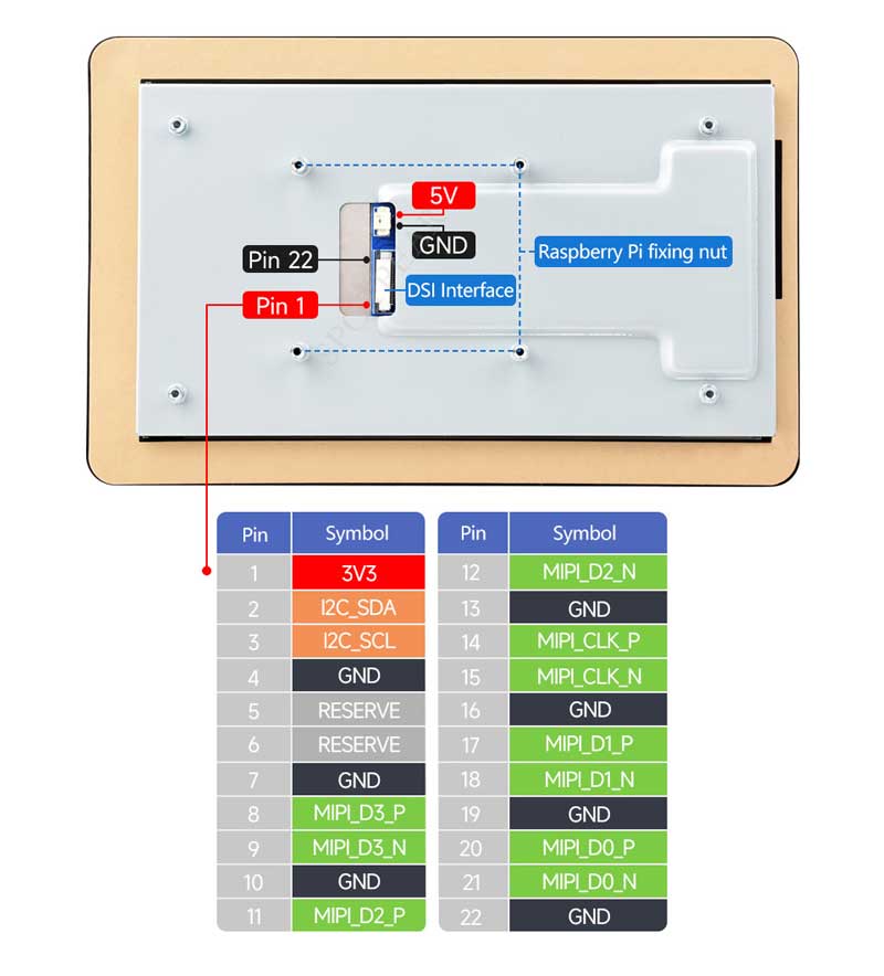
Interfaces
Usage Instructions
Raspberry Pi
Pi5 Hardware Connection
1. Use the "FFC Cable 22PIN 200mm (opposite direction)" to connect the DSI port of the display to the 22PIN DSI port of the Raspberry Pi motherboard.
2. Use the "GPIO cable" to connect the power connector of the display to the 5V GND pin header of the Raspberry Pi motherboard.
3. Secure the Raspberry Pi to the display with M2.5 screws.
The installation effect is as follows: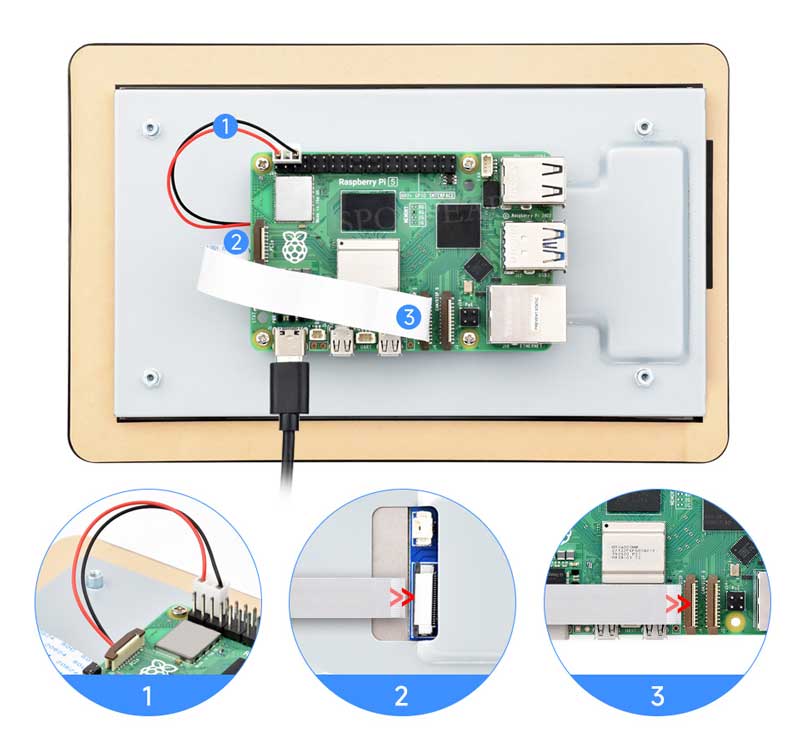
Note: Make sure that the DSI cable is connected in correct direction and 5V power is supplied through the GPIO pins.
Pi4B/3B+/3B/3A+ Hardware Connection
1. Use the "DSI-Cable-12cm" cable to connect the DSI port of the display to the 15PIN DSI port of the Raspberry Pi motherboard.
2. Use the "GPIO cable" to connect the power connector of the display to the 5V GND pin header of the Raspberry Pi motherboard.
3. Secure the Raspberry Pi to the display with M2.5 screws.
The installation effect is as follows: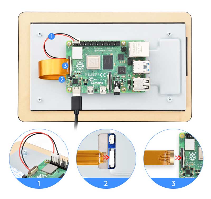
Note: Make sure that the DSI cable is connected in correct direction and 5V power is supplied through the GPIO pins.
Software Settings
Method 1: Flash the Pre-installed Image (recommended)
1. Select pre-installed image, download and unzip it as .img file
2. After the image flashing is completed, connect the TF card to the Raspberry Pi, start the Raspberry Pi, and wait for about 30 seconds for it to be displayed and touched normally.
Method 2: Install the Driver Manually
1. Connect the TF card to the PC, download and use Raspberry Pi Imager to flash the corresponding system image.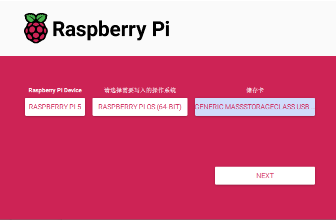
2. After the burning is completed, connect the TF card to the Raspberry Pi, start the Raspberry Pi, and log in to the terminal of the Raspberry Pi (you can connect the Raspberry Pi to the HDMI display or use ssh to log in remotely).
3. Run the following command on the terminal to install the driver:
(This method is only suitable for 64-bit systems)
 wget https://files.waveshare.com/wiki/common/Panel-waveshare-dsi2-driver.zip
 unzip Panel-waveshare-dsi2-driver.zip
 cd panel-waveshare-dsi2-driver
 make
 sudo cp ./waveshare-panel-regulator.ko /lib/modules/$(uname -r)
 sudo cp ./panel-waveshare-dsi-v2.ko /lib/modules/$(uname -r)
 sudo depmod
 sudo modprobe waveshare-panel-regulator
 sudo modprobe panel-waveshare-dsi-v2
 sudo dtc -I dts -O dtb -o vc4-kms-dsi-waveshare-panel-v2.dtbo vc4-kms-dsi-waveshare-panel-v2.dts
 sudo cp vc4-kms-dsi-waveshare-panel-v2.dtbo /boot/overlays/
Edit config.txt file
sudo nano /boot/firmware/config.txt
Add the following code at the end of the file
dtoverlay=vc4-kms-dsi-waveshare-panel-v2,7_0_inch_a
4. Save and exit, restart and wait for about 30 seconds for normal display and touch to work.
Adjusting Backlight Brightness
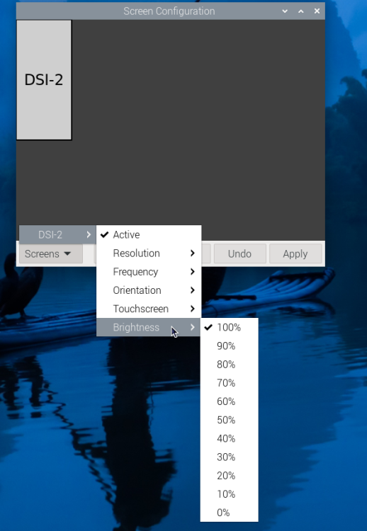
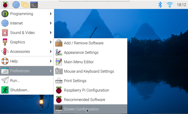
- 1. Open the "Screen Configuration" application;
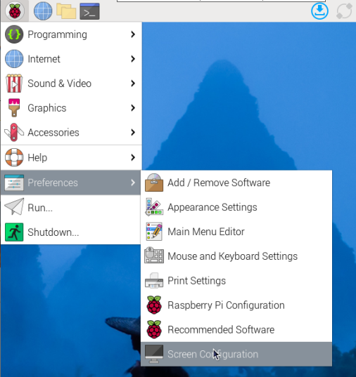
- 2. Go to "Screen" -> "DSI-2" -> "Brightness", check the backlight brightness you need to set, and finally click "Apply" to complete the backlight setting.
Waveshare also provides a corresponding demo (the demo is only used for Bookworm and Bullseye systems), users can download, install and use in the following way:
wget https://files.waveshare.com/wiki/common/Brightness.zip
unzip Brightness.zip
cd Brightness
sudo chmod +x install.sh
./install.sh
After the installation is completed, you can open the demo in the Start Menu -> Accessories -> Brightness, as shown below:
In addition, you can also control the brightness of the backlight by entering the following command on the terminal:
echo X | sudo tee /sys/class/backlight/*/brightness
Where X represents any number from 0 to 255. 0 means the darkest backlight, and 255 means the brightest backlight. For example:
echo 100 | sudo tee /sys/class/backlight/*/brightness
echo 0 | sudo tee /sys/class/backlight/*/brightness
echo 255 | sudo tee /sys/class/backlight/*/brightness
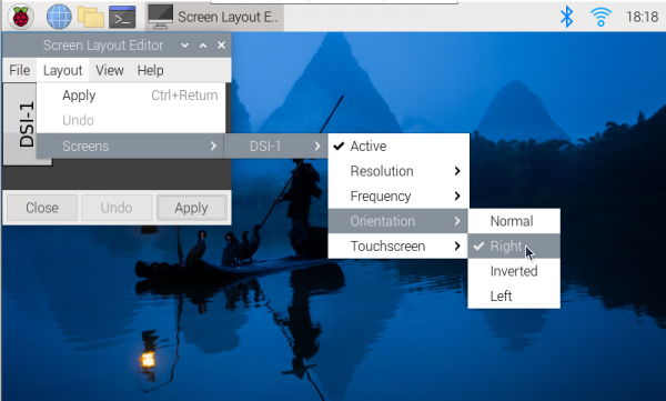
Bookworm Touch Screen Rotation
- 1. Open the "Screen Configuration" application;
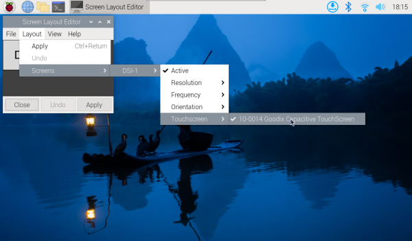
- 2. Go to Screen - > DSI-1 - > Touchscreen and check 10-0014 Goodix Capacitive TouchScreen;
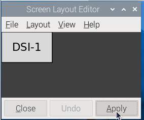
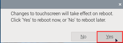
- 3.Click Apply, then close the current window, and reboot according to the pop-up prompts to complete the specified touch screen;
- 4.Go to Screen -> DSI-1 -> Orientation, check the direction you need to rotate, and finally click Apply to complete the display and touch synchronous rotation.
Note: Only the Bookworm system supports the above synchronization rotation method. For the Bullseye and Butser systems, manual separate settings for touch rotation are required after displaying the rotation.
lite Version Display Rotation
sudo nano /boot/firmware/cmdline.txt
#Add a command to display the rotation angle at the beginning of the cmdline.txt file, and save it to take effect after restarting
#Display rotation 90 degrees
video=DSI-1:720x1280M@60,rotate=90
#Display rotation 180 degrees
video=DSI-1:720x1280M@60,rotate=180
#Display rotation 270 degrees
video=DSI-1:720x1280M@60,rotate=270
Note: If you are using Pi5/CM4, the actual recognized DSI display number will prevail, for example DSi-2.
Touch Rotation
sudo nano /etc/udev/rules.d/99-waveshare-touch.rules

#Set the command of touch rotation angle within the file, and it will take effect after the restart
#90°:
ENV{ID_INPUT_TOUCHSCREEN}=="1", ENV{LIBINPUT_CALIBRATION_MATRIX}="0 -1 1 1 0 0"

#180°:
#ENV{ID_INPUT_TOUCHSCREEN}=="1", ENV{LIBINPUT_CALIBRATION_MATRIX}="-1 0 1 0 -1 1"

#270°:
#ENV{ID_INPUT_TOUCHSCREEN}=="1", ENV{LIBINPUT_CALIBRATION_MATRIX}="0 1 0 -1 0 1"

#Save, exit, and reboot
sudo reboot
Luckfox-Omni3576
Hardware Connection
1. Use a 22PIN FPC cable to connect the DSI interface of the display to the DSI interface of the Omni3576 motherboard.
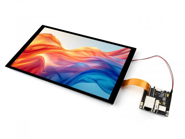
2. Use a 2PIN power cable to connect the power interface of the display to the 40PIN GPIO interface on the Omni3576 motherboard. As shown in the figure below: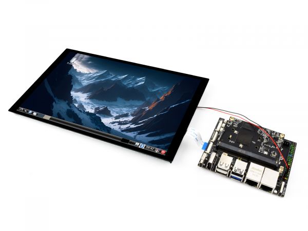
Software Settings
1. Download and use the mirror file from the Luckfox official website to flash the corresponding system image.
2. Connect the Omni3576 motherboard to a 5V power supply, and the screen will light up after the system starts
View Screen Information
- The screen ID available in the current system can be viewed using the following command:
sudo cat /sys/kernel/debug/dri/0/summary
- Under normal circumstances, the following output will be obtained:
Video Port0: DISABLED
Video Port1: ACTIVE
    Connector:DSI-1     Encoder: DSI-203
        bus_format[100a]: RGB888_1X24
        overlay_mode[0] output_mode[0] SDR[0] color-encoding[BT.709] color-range[Full]
    Display mode: 800x1280p60
        clk[70000] real_clk[69883] type[48] flag[a]
        H: 800 840 860 880
        V: 1280 1300 1304 1324
        Fixed H: 800 840 860 880
        Fixed V: 1280 1300 1304 1324
    Esmart1-win0: ACTIVE
        win_id: 1
        format: XR24 little-endian (0x34325258) pixel_blend_mode[0] glb_alpha[0xff]
        color: SDR[0] color-encoding[BT.601] color-range[Limited]
        rotate: xmirror: 0 ymirror: 0 rotate_90: 0 rotate_270: 0
        csc: y2r[0] r2y[0] csc mode[0]
        zpos: 1
        src: pos[0, 0] rect[800 x 1280]
        dst: pos[0, 0] rect[800 x 1280]
        buf[0]: addr: 0x00000000fe44e000 pitch: 3200 offset: 0
Video Port2: DISABLED
Display Rotation
- Rotation command
#Rotate 90 degrees
xrandr -o left
#Rotate 270 degrees
xrandr -o right
#Rotate 180 degrees
xrandr -o inverted
#Rotate 0 degrees
xrandr -o normal
- The effect of using xrandr rotation is a one-time and the screen orientation is restored after the system restarts. If you want the device to rotate automatically upon startup, you need to modify the configuration file:
sudo vim /etc/X11/xorg.conf.d/10-monitor.conf
Add the following statement:
### Valid values for rotation are "normal", "left", "right"
Section "Monitor"
#    Identifier "Default Monitor"
    Identifier  "DSI-1"
    Option      "Rotate" "left"
EndSection
Touch Rotation
- After the system displays rotation, the touch direction is inconsistent, and you need to perform the following operations to touch and rotate:
sudo vim /etc/udev/rules.d/99-luckfox-touch.rules
- Add the corresponding configuration according to your rotation direction, save it, and restart the development board.
90 degrees:
ENV{ID_INPUT_TOUCHSCREEN}=="1", ENV{LIBINPUT_CALIBRATION_MATRIX}="0 -1 1 1 0 0"
180 degrees:
ENV{ID_INPUT_TOUCHSCREEN}=="1", ENV{LIBINPUT_CALIBRATION_MATRIX}="-1 0 1 0 -1 1"
270 degrees:
ENV{ID_INPUT_TOUCHSCREEN}=="1", ENV{LIBINPUT_CALIBRATION_MATRIX}="0 1 0 -1 0 1"
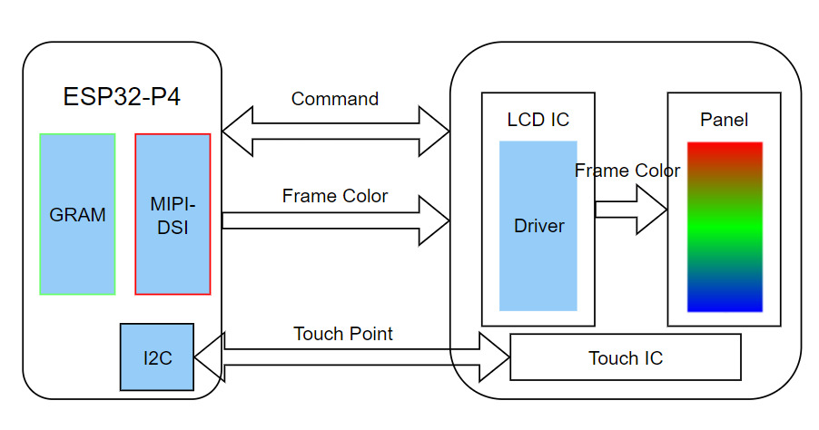
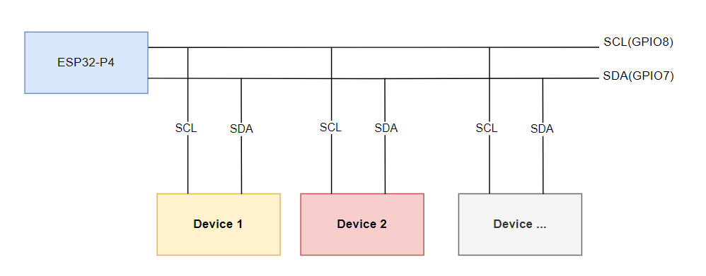
ESP32-P4
Screen Driver
The ESP32-P4-NANO drives the screen via MIPI 2-lane
- The screen driver has been packaged as a component, with the component located at ESP Component Registry
Useidf.py add-dependency "waveshare/esp_lcd_jd9365_10_1"to add components to your ESP-IDF project - You can also directly view the ESP32-P4-NANO driver for this screen on the Wiki: ESP32-P4-NANO_MIPI-DSI
Backlight Control
After connecting the ESP32-P4-NANO with the matching FPC cable and power cable, the backlight can be controlled by writing 0x00~0xFF (full brightness) to the 0x45 device and 0x86 register on the screen through the ESP32-P4-NANO I2C
If you use the ESP32-P4-NANO BSP component, you can control it directly by the following functions
bsp_display_brightness_init();   // Initialize the backlight

bsp_display_backlight_on();      // Turn on the backlight, default full brightness

Bsp_display_backlight_off();      // Turn off the backlight

bsp_display_brightness_set(95); // Set the specific backlight brightness, 0~100
Resources
2D Diagrams
Support
Monday-Friday (9:30-6:30) Saturday (9:30-5:30)
Email: services01@spotpear.com