- sales/support
Google Chat:---
- sales
+86-0755-88291180
- sales01
sales@spotpear.com
- sales02
dragon_manager@163.com
- support
tech-support@spotpear.com
- CEO-Complaints
zhoujie@spotpear.com
- Only Tech-Support
WhatsApp:13246739196
- Purchase/Shipping/Refund
WhatsApp:13424403025
12.3-DSI-TOUCH-A User Guide
Introduction
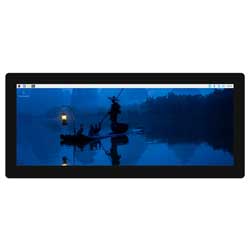
The 12.3-DSI-TOUCH-A is a portrait touchscreen LCD display designed for interactive projects such as tablets, entertainment systems, and information dashboards.
Features
- 12.3inch DSI touch screen, ten-point capacitive touch control
- IPS display panel with hardware resolution of 720×1920
- Optical bonding toughened glass panel, clearer picture quality
- Toughened glass capacitive touch panel, hardness up to 6H
- Drive the LCD through the DSI interface, with a refresh rate of up to 60Hz
- Supports software control of backlight brightness
- All-metal back cover design, pure passive cooling design
Electrical Specifications
| Parameters | Minimum Value | Standard Value | Maximum Value | Unit | Note |
| Input voltage | 4.75 | 5.00 | 5.25 | V | Note 1 |
| Input current | - | 1 | TBD | A | Note 2 |
| Operating temperature | 0 | 25 | 60 | ℃ | Note 3 |
| Storage temperature | -10 | 25 | 70 | ℃ | Note 3 |
•Note 1: Input voltages exceeding the maximum or improper operation may cause permanent damage to the device.
•Note 2: The input current needs to be ≥ 1A, otherwise it will cause the startup failure or display abnormality, and staying in an abnormal state for a long time may cause permanent damage to the device.
•Note 3: Please do not store the display panel in a high-temperature and high-humidity environment for a long time. The display panel should operate within its limits, otherwise it may be damaged.
Interfaces
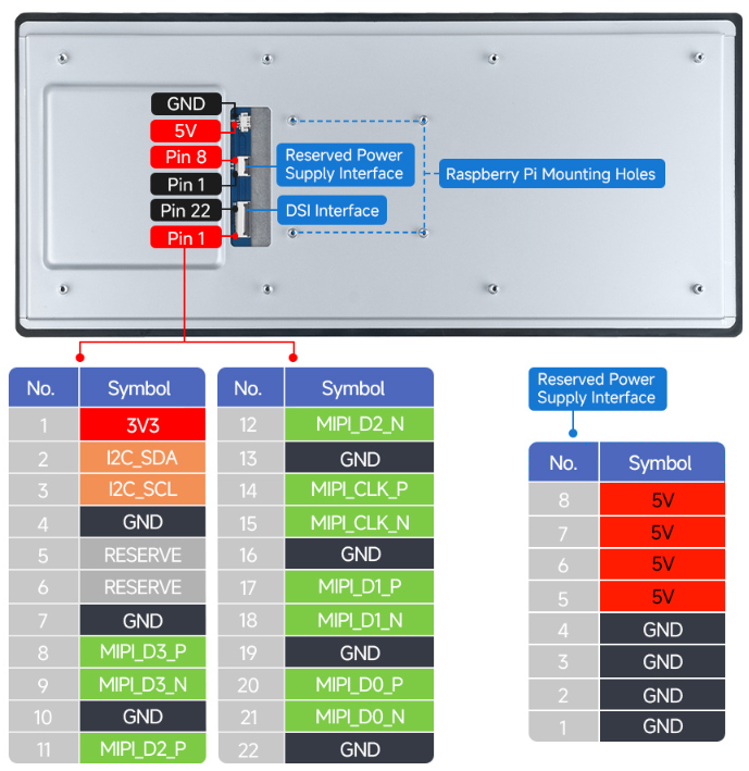
Working with Raspberry Pi
Pi5/CM5 Hardware Connection
1. Use the “FFC Cable 22PIN 200mm (opposite direction)” to connect the DSI port of the display to the 22PIN DSI port of the Raspberry Pi motherboard.
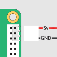
2. Use the "GPIO cable” to connect the power connector of the display to the 5V GND pin header of the Raspberry Pi motherboard.
3. Secure the Raspberry Pi to the display with M2.5 screws.
The installation effect is as follows: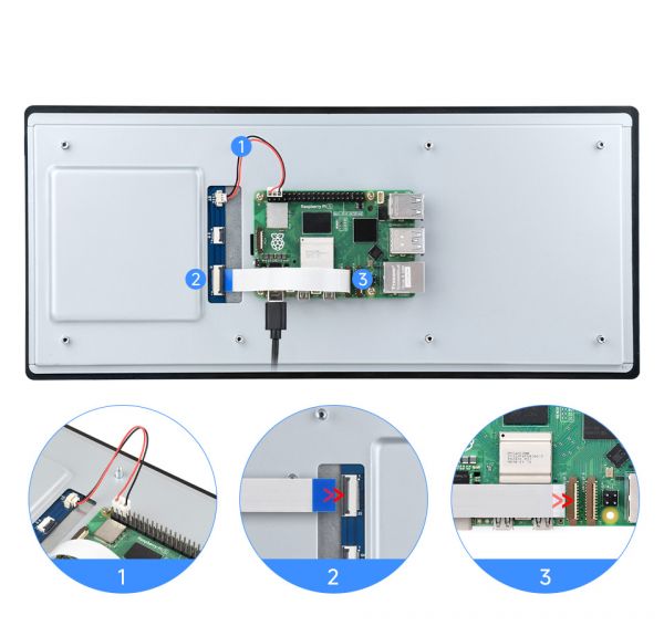
Note: Make sure that the DSI cable is connected in correct direction and 5V power is supplied through the GPIO pins.
Software Settings
Method 1: Burn the pre-installed image (recommended)
1. Select pre-installed image, download and unzip it as .img file
2. After the image flashing is completed, connect the TF card to the Raspberry Pi, start the Raspberry Pi, and wait for about 30 seconds for it to be displayed and touched normally.
Method 2: Install the driver manually
1. Connect the TF card to the PC, download and use Raspberry Pi Imager to flash the corresponding system image.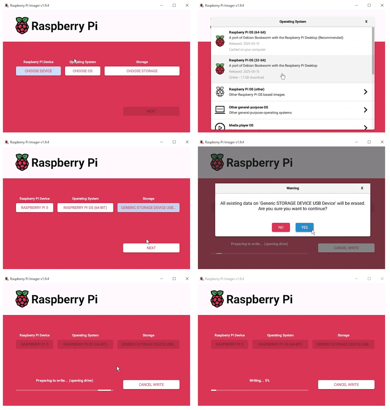
2. After the flashing is completed, connect the TF card to the Raspberry Pi, start the Raspberry Pi, and log in to the terminal of the Raspberry Pi (you can connect the Raspberry Pi to the HDMI display or use ssh to log in remotely).
3. Run the following command on the terminal to install the driver:
(This method is only applicable to 64-bit systems)
 wget https://files.waveshare.com/wiki/common/Panel-waveshare-dsi2-driver.zip
 unzip Panel-waveshare-dsi-v2-driver.zip
 cd panel-waveshare-dsi-v2-driver
 make
 sudo cp ./waveshare-panel-regulator-test.ko /lib/modules/$(uname -r)
 sudo cp ./panel-waveshare-dsi-v2-test.ko /lib/modules/$(uname -r)
 sudo depmod
 sudo modprobe waveshare-panel-regulator-test
 sudo modprobe panel-waveshare-dsi-v2-test
 sudo dtc -I dts -O dtb -o vc4-kms-dsi-waveshare-panel-v2-test.dtbo vc4-kms-dsi-waveshare-panel-v2-test-overlay.dts
 sudo cp vc4-kms-dsi-waveshare-panel-v2-test.dtbo /boot/firmware/overlays/
Edit config.txt file
sudo nano /boot/firmware/config.txt
- Note: Since Pi 5/CM5 has two MIPI DSI interfaces, please make sure that the correct DSI interfaces and commands are used. DSI1 is recommended by default.
Add the following code at the end of the file
dtoverlay=vc4-kms-v3d
#DSI1 Use
dtoverlay=vc4-kms-dsi-waveshare-panel-v2-test,12_3_inch_a_4lane
#DSI0 Use
#dtoverlay=vc4-kms-dsi-waveshare-panel-v2-test,12_3_inch_a_4lane,dsi0
Save and exit, restart and wait for about 30 seconds for normal display and touch to work.
Working with Luckfox-Omni3576
Hardware Connection
1. Use a 22PIN FPC cable to connect the DSI interface of the display to the DSI interface of the Omni3576 motherboard.
2. Use a 2PIN power cable to connect the power interface of the display to the 40PIN GPIO interface on the Omni3576 motherboard. As shown in the figure below: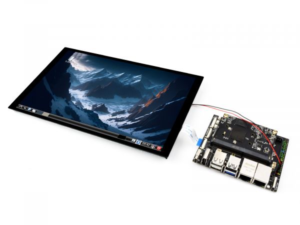
Software Settings
1. Download and use the mirror file from the Luckfox official website to flash the corresponding system image.
2. Connect the Omni3576 motherboard to a 5V power supply, and the screen will light up after the system starts
View Screen Information
- The screen ID available in the current system can be viewed using the following command:
sudo cat /sys/kernel/debug/dri/0/summary
- Under normal circumstances, the following output will be obtained:
Video Port0: DISABLED
Video Port1: ACTIVE
    Connector:DSI-1     Encoder: DSI-203
        bus_format[100a]: RGB888_1X24
        overlay_mode[0] output_mode[0] SDR[0] color-encoding[BT.709] color-range[Full]
    Display mode: 800x1280p60
        clk[70000] real_clk[69883] type[48] flag[a]
        H: 800 840 860 880
        V: 1280 1300 1304 1324
        Fixed H: 800 840 860 880
        Fixed V: 1280 1300 1304 1324
    Esmart1-win0: ACTIVE
        win_id: 1
        format: XR24 little-endian (0x34325258) pixel_blend_mode[0] glb_alpha[0xff]
        color: SDR[0] color-encoding[BT.601] color-range[Limited]
        rotate: xmirror: 0 ymirror: 0 rotate_90: 0 rotate_270: 0
        csc: y2r[0] r2y[0] csc mode[0]
        zpos: 1
        src: pos[0, 0] rect[800 x 1280]
        dst: pos[0, 0] rect[800 x 1280]
        buf[0]: addr: 0x00000000fe44e000 pitch: 3200 offset: 0
Video Port2: DISABLED
Show Rotation
- Rotation command
#Rotate 90 degrees
xrandr -o left
#Rotate 270 degrees
xrandr -o right
#Rotate 180 degrees
xrandr -o inverted
#Rotate 0 degrees
xrandr -o normal
- The effect of using xrandr rotation is a one-time and the screen orientation is restored after the system restarts. If you want the device to rotate automatically upon startup, you need to modify the configuration file:
sudo vim /etc/X11/xorg.conf.d/10-monitor.conf
Add the following statement:
### Valid values for rotation are "normal", "left", "right"
Section "Monitor"
#    Identifier "Default Monitor"
    Identifier  "DSI-1"
    Option      "Rotate" "left"
EndSection
Touch Rotation
- After the system displays rotation, the touch direction is inconsistent, and you need to perform the following operations to touch and rotate:
sudo vim /etc/udev/rules.d/99-luckfox-touch.rules
- Add the corresponding configuration according to your rotation direction, save it, and restart the development board.
90 degrees:
ENV{ID_INPUT_TOUCHSCREEN}=="1", ENV{LIBINPUT_CALIBRATION_MATRIX}="0 -1 1 1 0 0"
180 degrees:
ENV{ID_INPUT_TOUCHSCREEN}=="1", ENV{LIBINPUT_CALIBRATION_MATRIX}="-1 0 1 0 -1 1"
270 degrees:
ENV{ID_INPUT_TOUCHSCREEN}=="1", ENV{LIBINPUT_CALIBRATION_MATRIX}="0 1 0 -1 0 1"
Safety Instructions
To avoid any malfunction or damage to this product, please follow the following instructions:
- Turn off your Raspberry Pi computer and disconnect the external power supply before connecting the device.
- If the cable falls off, pull the locking device on the connector forward, insert the ribbon cable with the metal contacts facing you, and push the locking device back into place.
- This device should be operated in a dry environment between 0~60℃.
- Do not expose the device to water or humid environments during operation, nor place it on conductive surfaces.
- Do not expose it to any overheated environment.
- Be careful not to fold or tighten the ribbon cable.
- Be careful when screwing in the parts. Misalignment of threads may cause irreparable damage and void the warranty.
- Please be careful during transportation to avoid mechanical or electrical damage to printed circuit boards and connectors.
- Store in a cool and dry place.
- Avoid sudden temperature changes, otherwise it may lead to the accumulation of moisture inside the device.
- The screen is fragile and may break.
Resources
Support
Monday-Friday (9:30-6:30) Saturday (9:30-5:30)
Email: services01@spotpear.com