- sales/support
Google Chat:---
- sales
+86-0755-88291180
- sales01
sales@spotpear.com
- sales02
dragon_manager@163.com
- support
tech-support@spotpear.com
- CEO-Complaints
zhoujie@spotpear.com
- Only Tech-Support
WhatsApp:13246739196
- Purchase/Shipping/Refund
WhatsApp:13424403025
- HOME
- >
- ARTICLES
- >
- Common Moudle
- >
- USB HUB
USB-TO-RS232-485 User Guide
Overview
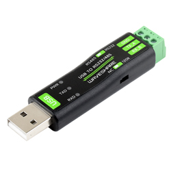
USB TO RS232/485 is a USB to RS232/485 non-isolated serial port converter, featuring the original FT232RNL chip for improved stability and compatibility. It comes with a built-in self-recovering fuse, TVS protection circuit, etc. USB TO RS232/485 offers simple operation, zero-delay automatic transmission and reception conversion, and boasts characteristics such as fast, stable, reliable and safe communication.
Features
- Onboard Original FT232RNL chip. Fast communication, stable and reliable, better compatibility.
- Onboard TVS (Transient Voltage Suppressor), effectively suppresses surge voltage and transient spike voltage in the circuit, lightning-proof & anti-electrostatic.
- Onboard self-recovery fuse and protection diodes, ensure the current/voltage stable outputs, provide over-current/over-voltage proof, and improve shockproof performance.
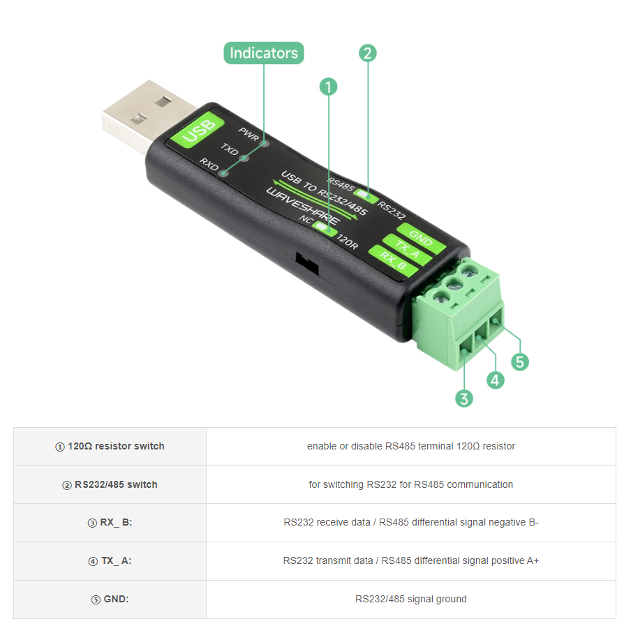
- Onboard RS232/485 communication switching circuit, configured by switch.
- Onboard 120R terminal resistor on the RS485 interface, enabled/disabled via switch.
- 3x LEDs for indicating the power and transceiver status.
- ABS case design, small in size, easy to use, portable and cost-effective.
Parameters
| Model | USB to RS232/RS485 | |
| Host Interface | USB | |
| Device Interface | RS232/RS485 | |
| USB Interface | Operating Level | 5V |
| Interface | Type-A male | |
| Protection | 200mA self-recovery fuse | |
| Transmission Distance | About 5m | |
| RS232 Interface | Interface | Screw Terminal |
| Transmission Distance | About 15m | |
| Transmission Mode | Point to Point | |
| Baud Rate | 300 bps ~ 921600bps | |
| RS485 Interface | Interface | Screw Terminal |
| Direction Control | Hardware automatic control | |
| Protection | Provide TVS diode protection, anti-surge, and ESD protection (onboard 120R resistor) | |
| Transmission Distance | About 1200m (at low rate) | |
| Transmission Mode | Point to multi-point (up to 32 nodes, add the relay for up to 16 nodes) | |
| Baudrate | 300 bps ~ 921600bps | |
| Indicator | PWR | Red power indicator, connect to USB, light on when the voltage is detected |
| TXD | Transmitting indicator, green light is on when data is sent from the USB interface | |
| RXD | Receiving indicator, blue light is on when the data is sent back from the device interface | |
| Usage Environment | Temperature Range | -15℃ ~ 70℃ |
| Humidity Range | 5% ~ 95%RH | |
| OS | Mac, Linux, Android, Windows 11 / 10 / 8.1 / 8 / 7 | |
Onboard Interface
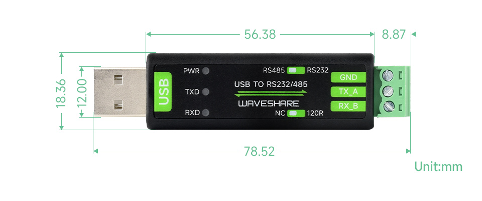
Dimensions
Driver Installation
USB Driver Installation
- Download the VCP Driver.
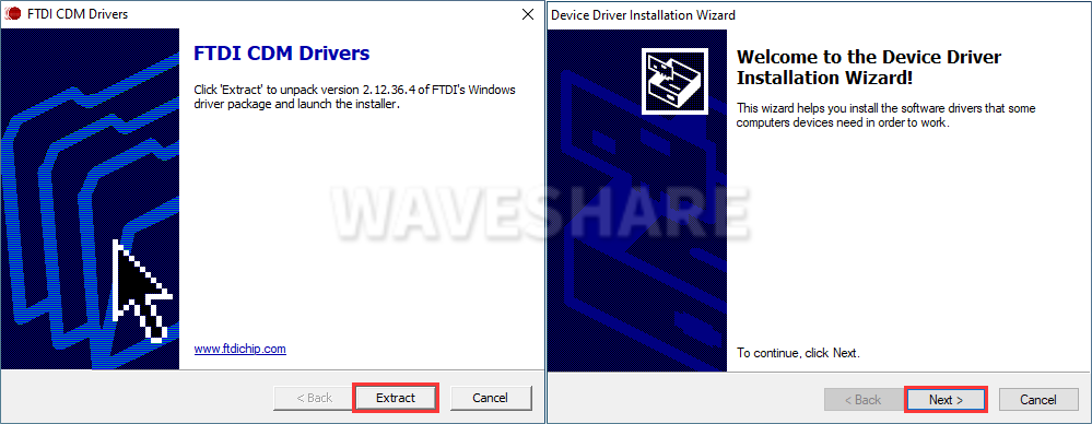
- Double click on CDM212364_Setup.exe and install it.
- Click on Extract, and then "NEXT".
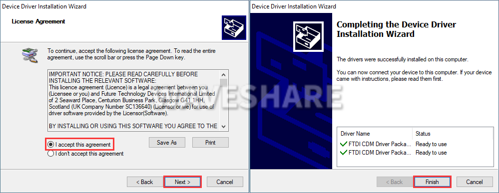
- Click on I accept this agreement, and then click on "NEXT", and click on "Finish".
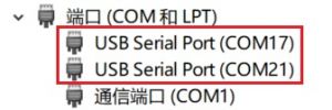
- After connecting the PC, you can see the usable COM port number in the device manager.
Hardware Test
Test environment: PC (Windows)
Required accessories:
- USB TO RS232/485 x 2pcs
- USB-A male-to-female cable x 1 (or directly connect to the USB port of the computer)
- Wires
RS232 Test
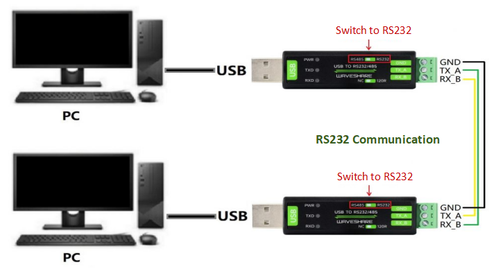
- Connect the RS232 interface of the USB TO RS232/485 module to the RS232 interface, that is, RXD and TXD are connected in a staggered manner, GND and GND are connected, and the toggle switch on top of the module is switched to RS232, and the connection diagram is referenced as follows:
- Open two SSCOM windows and the corresponding COM port numbers.

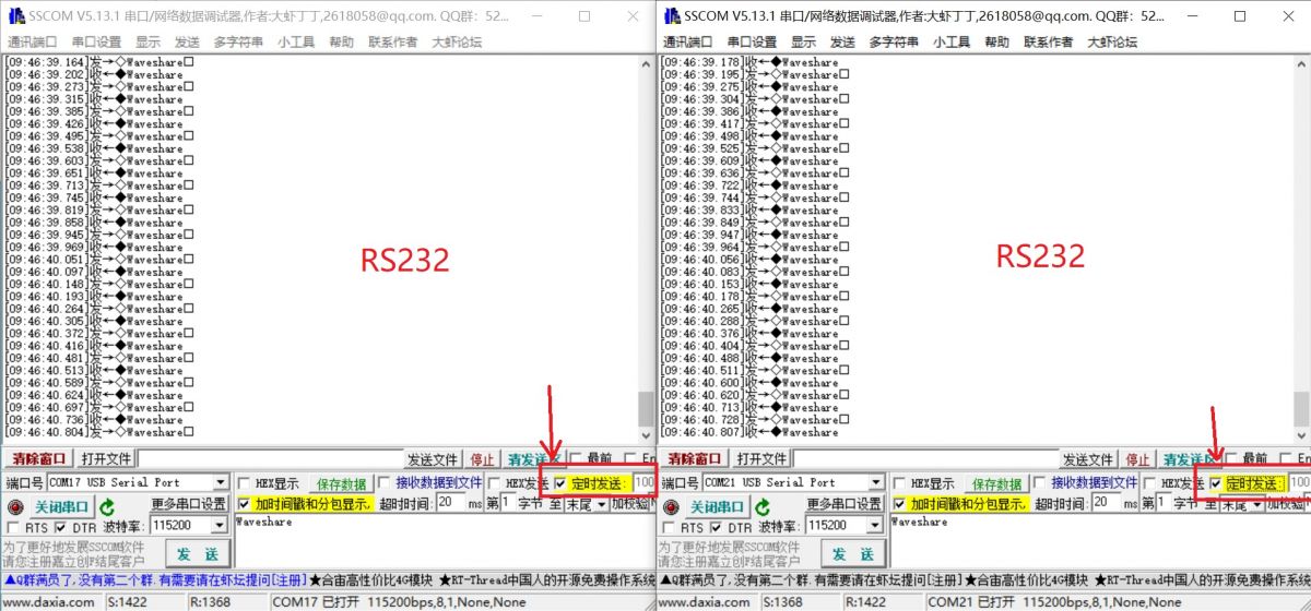
- Select the baud rate as 115200, input the characters to be sent, check show time and package, and click on Open COM:

- Set the two SSCOM windows sending at 100ms intervals, and then you can see the 2 Windows send and receive data normally, the effect as shown below:
RS485 Test
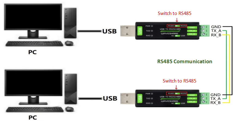
- Connect the RS485 connector of the USB TO RS232/485 module, that is, A+ --> A+, B- --> B-, GND --> GND, and switch the toggle switch on it to RS485, the connection diagram is referenced below:
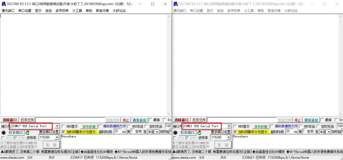
- Open two SSCOM windows on the PC and the corresponding COM ports:
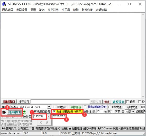
- Select the baud rate as 115200, input the characters to be sent, check show time and package, and Open COM.
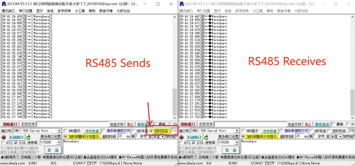
- Select one SSCOM, send it at 100ms intervals, and then you can the 2 Windows send and receive data as shown below:
Resource
Datasheet
Software & Driver
- VCP driver (or you can download it from FTDI website)
- Support Linux driver free.
- SSCOM
Support
Monday-Friday (9:30-6:30) Saturday (9:30-5:30)
Email: services01@spotpear.com
TAG:
Pan-Tilt Kit
RS485 to Ethernet
Jetson Nano
RS485
Raspberry Pi Pico Screen
Raspberry Pi USB Global Shutter Camera 1MP OV9281 120fps Black/White 120fps also For Jeston RDK
Core3566104032
SpotPear
ESP32-S3
ESP32-P4 Smart 86 TV Box Development Board 4 inch 720x720 Display TouchScreen RS485 Relay Camera RJ45 ETH
Raspberry Pi Pico Basics User Guide
LuckFox SC3336
Raspberry Pi 14 inch LCD 2K HDMI /Type C Display Capacitive TouchScreen 2160x1440 For Jetson Nano/mini Computer PC
White
Font-Modulation-Tutorial User Guide
Raspberry Pi 5
Raspberry Pi Pico 1.14inch LCD
RV1106
Industrial ESP32-S3 Relay 8-Channel 8-Ch ESP32-WROOM IOT WiFi Bluetooth HAT For Arduino
ESP32 C3 Round LCD Development Board Electronic EYE 0.71 inch Display Watch Screen GC9A01 160x160