




- sales/support
Google Chat:---
- sales
+86-0755-88291180
- sales01
sales@spotpear.com
- sales02
dragon_manager@163.com
- support
tech-support@spotpear.com
- CEO-Complaints
zhoujie@spotpear.com
- Only Tech-Support
WhatsApp:13246739196
- Purchase/Shipping/Refund
WhatsApp:13424403025
- HOME
- >
- ARTICLES
- >
- Common Moudle
- >
- ESP
ESP32-S3-ePaper-1.54G User Guide
Onboard Resources
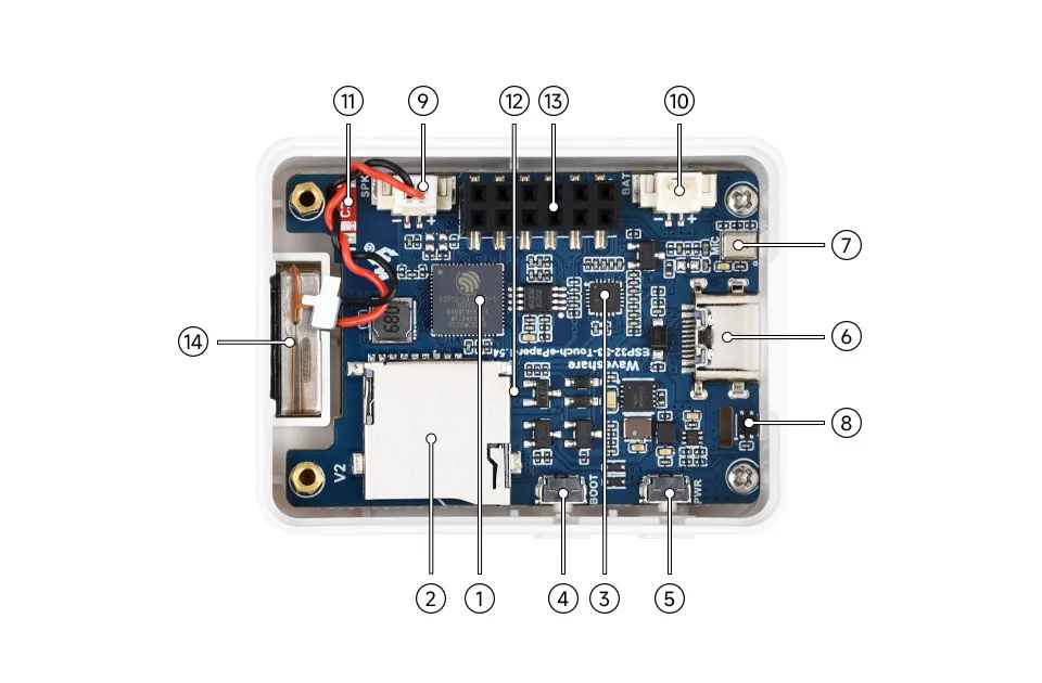
- ESP32-S3-PICO-1-N8R8 Wi-Fi and Bluetooth SoC, running at 240MHz, with integrated 8MB Flash and 8MB PSRAM in a stacked package
- TF Card Slot TF card must be formatted as FAT32 for use
- ES8311 Audio Codec Chip Supports audio input and output, low-power design, suitable for voice recognition and playback applications
- BOOT Button Press and hold the BOOT button to power on again to enter download mode
- PWR Power Button Hold BOOT, re-power on to enter download mode
- Type-C Interface ESP32-S3 USB interface for program flashing and serial logging
- Microphone For audio capture
- SHTC3 Temperature and Humidity Sensor Provides ambient temperature and humidity measurement, enabling environmental monitoring function
- MX1.25 2PIN Speaker Header Audio signal output, for connecting external speaker
- MX1.25 2PIN Lithium Battery Header For connecting a lithium battery
- Onboard Antenna Supports 2.4GHz Wi-Fi (802.11 b/g/n) and Bluetooth 5 (LE)
- PCF85063 (back side) RTC clock chip, supports time-keeping function
- 2 × 6PIN 2.54mm Pitch Female Header Can be used for expansion
- Speaker Plays audio
Peripheral Quick Reference
| Module | Device / Function | Interface | Address / Parameters | GPIO / Signals |
|---|---|---|---|---|
| E-Paper | 1.54G | SPI | 200 x 200 | EPD_PWR=GPIO6, EPD_BUSY=GPIO8, EPD_DC=GPIO10, EPD_CS=GPIO11, EPD_SCLK=GPIO12, EPD_SDI=GPIO13, EPD_RST=GPIO9 |
| RTC | PCF85063ATL | I2C | Common 7-bit address 0x51, 32.768 kHz crystal | SCL=GPIO48, SDA=GPIO47, INT=GPIO5 |
| Battery Sampling | VBAT divided to ADC | ADC | R21 pull-up 200K, R38 pull-down 200K; VBAT=VADC×2 | GPIO4 / BAT_ADC |
| Power Control | BAT_KEY / BAT_Control | GPIO | PWR power function circuit | BAT_KEY=GPIO18, BAT_Control=GPIO17 |
| Audio Capture/Playback | ES8311 | I2S | Common 7-bit address: 0x18 | I2S_MCLK=GPIO14, I2S_SCLK=GPIO15, I2S_ASDOUT=GPIO16, I2S_LRCK=GPIO38, I2S_DSDIN=GPIO45, PA_EN=GPIO42, PA_CTRL=GPIO46 |
| Temperature & Humidity Sensor | SHTC3 | I2C | Common 7-bit address: 0x70 | SCL=GPIO48, SDA=GPIO47 |
| TF Card | TF Card Slot | SDIO | SD_CLK=GPIO39, SD_MOSI=GPIO41, SD_MISO=GPIO40 | |
| USB Type-C | ESP32-S3 native USB | USB | Download, logging | USB_N=GPIO19, USB_P=GPIO20 |
| UART0 | Default serial port | UART | Debug / externally accessible interface | U0TXD=GPIO43, U0RXD=GPIO44 |
| Charging Management | ETA6098 | Power | Single-cell Li-Ion battery charging/discharging | GH1.25 battery connector |
| 3.3V DC-DC | MP1605 | Power | System 3.3V | VCC3V3 |
ePaper Display Specifications
| Display Panel | E-Paper | Display Size | 1.54inch |
|---|---|---|---|
| Display Resolution | 200 × 200 | Grayscale Levels | 2 |
| Communication Interface | SPI | Full Refresh Time | 20s |
| Display Colors | Red, Yellow, Black, White | Fast Refresh Time | 15s |
| Viewing Angle | >170° | Display Mode | Reflective |
Pinout Definition
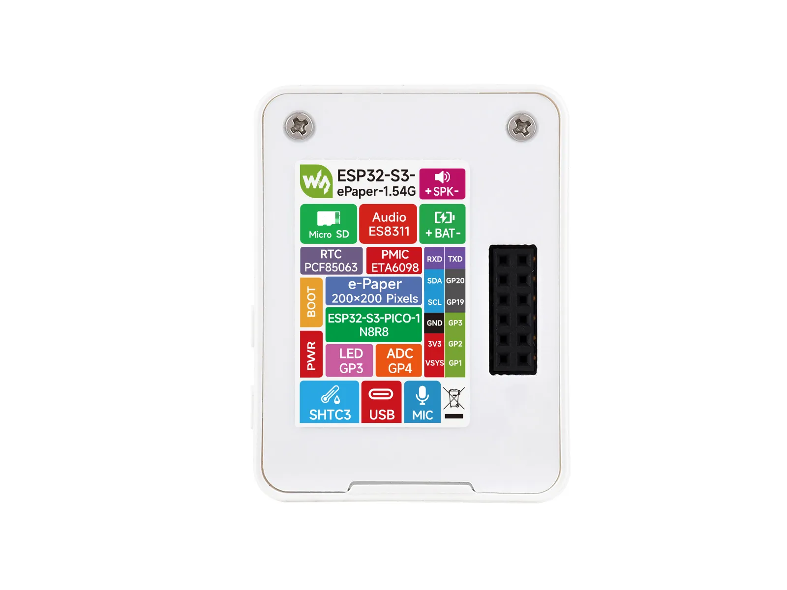
When using the reserved GPIO terminals on the ESP32-S3-ePaper-1.54G board, pay attention to wire colors and corresponding functions to avoid damaging the board due to incorrect wiring habits
Expansion Interface
| Type | Signals |
|---|---|
| Power | 5V / 3V3 / GND |
| I2C | SCL(GPIO48) / SDA(GPIO47) |
| UART | TX(GPIO43) / RX(GPIO44) |
| USB | USB_N(GPIO19)/ USB_P(GPIO20) |
| GPIO | GPIO1 / GPIO2 / GPIO3 |
Full GPIO Allocation
The table below lists the GPIOs already occupied by onboard circuits and those brought out to expansion headers.
| GPIO | Signal Name | Connected To | Remarks |
|---|---|---|---|
| GPIO0 | BOOT / Key1 | BOOT button | Strapping pin; button to enter download mode |
| GPIO1 | GPIO1 | Reserved female header | Expansion header GPIO1 |
| GPIO2 | GPIO2 | Reserved female header | Expansion header GPIO2 |
| GPIO3 | GPIO3 | Reserved female header | Expansion header GPIO3 |
| GPIO4 | BAT_ADC | Battery voltage divider sampling | R21 pull-up 200K, R38 pull-down 200K; VBAT=VADC×2 |
| GPIO5 | RTC_INT | PCF85063 RTC interrupt | - |
| GPIO6 | EPD3V3_EN | E-Paper power switch | E-paper 3.3V supply enable |
| GPIO7 | EPD_TP_RST | Reserved touch for e-Paper | Touch reset pin (reserved) |
| GPIO8 | EPD_BUSY | E-Paper busy status | - |
| GPIO9 | EPD_RST | E-Paper reset | - |
| GPIO10 | EPD_D/C | E-Paper data/command | - |
| GPIO11 | EPD_CS | E-Paper chip select | SPI slave select |
| GPIO12 | EPD_SCLK | E-Paper SPI clock | SPI communication clock |
| GPIO13 | EPD_SDI | E-Paper SPI data | SPI master output data |
| GPIO14 | I2S_MCLK | ES8311 audio master clock | - |
| GPIO15 | I2S_SCLK | ES8311 audio bit clock | - |
| GPIO16 | I2S_ASDOUT | ES8311 audio data output | I2S audio output |
| GPIO17 | BAT_Control | Battery power control | Battery charge/discharge management |
| GPIO18 | BAT_KEY | Battery power enable switch | - |
| GPIO19 | USB_N | USB Type-C D- | ESP32-S3 native USB |
| GPIO20 | USB_P | USB Type-C D+ | ESP32-S3 native USB |
| GPIO21 | EPD_TP_INT | E-Paper touch interrupt | Touch interrupt (reserved) |
| GPIO38 | I2S_LRCK | ES8311 audio frame clock | - |
| GPIO39 | SD_CLK | TF card SDIO clock | - |
| GPIO40 | SD_MISO | TF card SDIO data 0 | - |
| GPIO41 | SD_MOSI | TF card SDIO command | - |
| GPIO42 | PA_EN | ES8311 power supply enable | - |
| GPIO43 | U0TXD | Reserved UART TX female header | Expansion header TX |
| GPIO44 | U0RXD | Reserved UART RX female header | Expansion header RX |
| GPIO45 | I2S_DSDIN | ES8311 audio data input | I2S audio capture |
| GPIO46 | PA_CTRL | Audio amplifier enable - | |
| GPIO47 | SDA | I2C data bus | Shared by RTC/SHTC3/ES8311/EPD_TP |
| GPIO48 | SCL | I2C clock bus | Shared by RTC/SHTC3/ES8311/EPD_TP |
Precautions
- When connecting external I2C devices, avoid address conflicts with
0x18,0x70,0x51. GPIO19/GPIO20are connected to USB Type-C and are not recommended for use as general-purpose GPIO.GPIO0is the BOOT pin, andEN/CHIP_PUis the reset signal; they are not recommended for general user input.GPIO33toGPIO37are used for the integrated Octal SPI PSRAM and cannot be used for other functions.
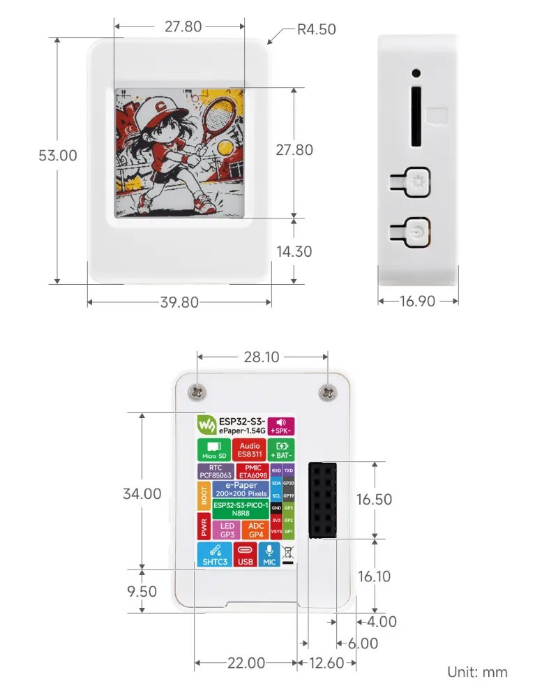
Dimensions
Working with Arduino
This chapter contains the following sections. Please read as needed:
Arduino Getting Started
New to Arduino ESP32 development and looking for a quick start? We have prepared a comprehensive Getting Started Tutorial for you.
- Section 0: Getting to Know ESP32
- Section 1: Installing and Configuring Arduino IDE
- Section 2: Arduino Basics
- Section 3: Digital Output/Input
- Section 4: Analog Input
- Section 5: Pulse Width Modulation (PWM)
- Section 6: Serial Communication (UART)
- Section 7: I2C Communication
- Section 8: SPI Communication
- Section 9: Wi-Fi Basics
- Section 10: Web Server
- Section 11: Bluetooth
- Section 12: LVGL GUI Development
- Section 13: Comprehensive Project
Note: This tutorial uses the ESP32-S3-Zero as a reference example, and all hardware code is based on its pinout. Before you start, we recommend checking the pinout of your development board to ensure the pin configuration is correct.
Setting Up Development Environment
1. Installing and Configuring the Arduino IDE
For the ESP32-S3-ePaper-1.54G development board, the Arduino IDE requires the installation of arduino-esp32 v3.2.0 or higher.
Please refer to the tutorial Installing and Configuring Arduino IDE to download and install the Arduino IDE and add ESP32 support.
2. Installing Libraries
- When installing Arduino libraries, there are typically two methods: Install Online and Install Offline. If the library installation requires Install Offline, you must use the provided library file.
- For most libraries, users can easily search for and install them via the Arduino IDE's online Library Manager. However, some open-source or custom libraries are not synchronized to the Arduino Library Manager and therefore cannot be found through online search. In this case, users can only install these libraries manually via offline methods.
- The example program package for the ESP32-S3-ePaper-1.54G development board can be downloaded from here. The
Arduino\librariesdirectory within the package already contains all the library files required for this tutorial.
| Library/File Name | Description | Version | Installation Method |
|---|---|---|---|
| SensorLib | Sensor control library | v0.3.1 | "Install Online" or "Install Offline" |
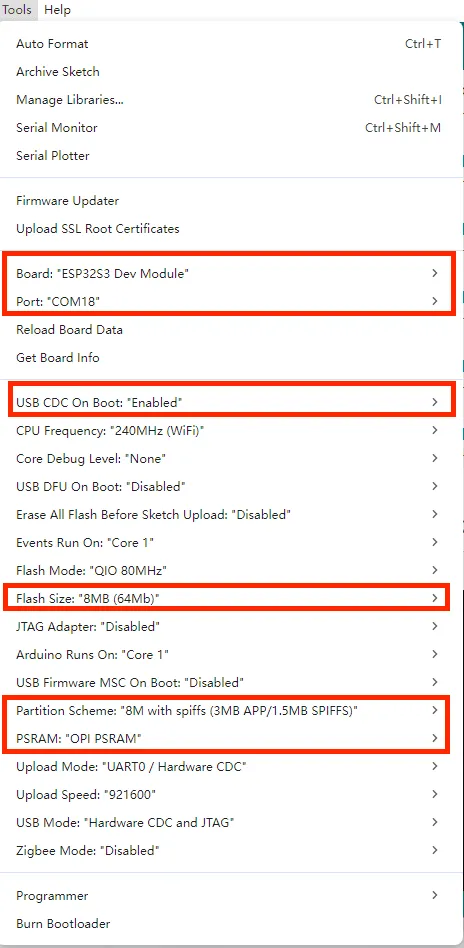
3. Arduino Project Parameter Settings
Example
The Arduino examples are located in the Arduino/examples directory of the example package.
| Example | Basic Program Description | Dependency Library |
|---|---|---|
| 01_ADC_Test | Get the voltage value of the lithium battery | - |
| 02_I2C_PCF85063 | Print real-time time of RTC chip | SensorLib |
| 03_I2C_STHC3 | Get data from SHTC3 temperature & humidity sensor | - |
| 04_SD_Card | Load and display TF card information | - |
| 05_WIFI_AP | Set to AP mode to obtain the IP address of the access device | - |
| 06_WIFI_STA | Set to STA mode to connect to Wi-Fi and obtain an IP address | - |
| 07_Audio_out | Read audio data and play audio | - |
| 08_E_paper_test | E-paper display refresh example | - |
01_ADC_Test
Example Description
- The analog voltage connected through the GPIO is converted to digital by the ADC, and then the actual lithium battery voltage is calculated and printed to the terminal.
Hardware Connection
- Connect the board to the computer using a USB cable
Code Analysis
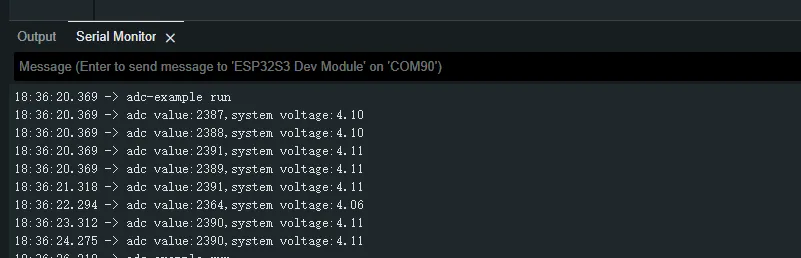
adc_bsp_init(void): Initializes ADC1, including creating an ADC one-shot trigger unit and configuring Channel 3 of ADC1.adc_get_value(float *value,int *data): Reads the value from Channel 3 of ADC1, calculates the corresponding voltage based on the reference voltage and resolution, and stores it at the location pointed to by the passed pointer. Stores 0 if the read fails.adc_example(void* parameter): After initializing ADC1, creates an ADC task. This task reads the ADC value every second and calculates the system voltage from the raw ADC reading.
Operation Result
After the program is compiled and downloaded, you can view the printed ADC values and voltage output by opening the Serial Monitor, as shown in the following image:
02_I2C_PCF85063
Example Description
- Through the I2C protocol, initialize the PCF85063 chip, set the time, and then periodically read the time and print it to the terminal
Hardware Connection
- Connect the board to the computer using a USB cable
Code Analysis
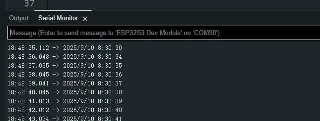
void i2c_rtc_loop_task(void *arg): Creates an RTC task to implement the RTC function, reading the clock of the RTC chip every second and outputting it to the terminal.
Operation Result
After the program is compiled and downloaded, open the serial port monitoring to see the RTC time of the printout, as shown in the following figure:
03_I2C_STHC3
Example Description
- Initialize the SHTC3 chip through the I2C protocol, and then print the temperature and humidity information read every 1 second to the terminal
Hardware Connection
- Connect the board to the computer using a USB cable
Code Analysis
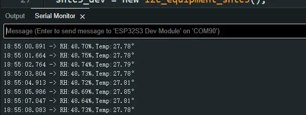
void i2c_SHTC3_loop_task(void *arg): Creates a task for the SHTC3 sensor to periodically obtain temperature and humidity data.
Operation Result
Open the serial port monitor, you can see the printed temperature and humidity data, as shown in the figure below:
04_SD_Card
Example Description
- Drive the TF card through SDMMC, and print the TF card information to the terminal after successfully mounting.
Hardware Connection
- Install a FatFs-formatted TF card into the board before powering on
Code Analysis
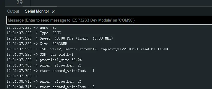
sdcard_init(void): Initializes the TF card using 1-line SDMMC mode.sdcard_loop_task(void *arg): A task to test TF card read/write functionality. You need to uncomment the#define sdcard_write_Testmacro definition.//#define sdcard_write_Test
Operation Result
Click on the serial port monitoring device, you can see the output information of the TF card, as shown in the figure below:
05_WIFI_AP
Example Description
- This example can set the development board as a hotspot, allowing phones or other devices in STA mode to connect to the development board.
Hardware Connection
- Connect the board to the computer using a USB cable
Code Analysis
In the
05_WIFI_AP.inofile, locatessidandpassword. Phones or other STA mode devices can then connect to the board using this SSID and password.const char *ssid = "ESP32_AP";const char *password = "12345678";
Operation Result
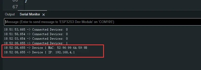
After flashing the program, open the Serial Terminal. If a device successfully connects to the hotspot, the MAC address of that device will be output, as shown:
06_WIFI_STA
Example Description
- This example configures the development board as a STA device to connect to a router, thereby accessing the system network.
Hardware Connection
- Connect the board to the computer using a USB cable
Code Analysis
In the
06_WIFI_STA.inofile, locatessidandpassword, and modify them to match the SSID and Password of an available router in your current environment.const char *ssid = "you_ssid";const char *password = "you_password";
Operation Result
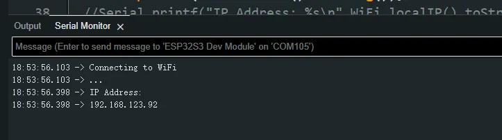
After flashing the program, open the Serial Terminal. If the device successfully connects to the hotspot, the obtained IP address will be output, as shown in the figure:
07_Audio_out
Example Description
- This example demonstrates playing PCM audio data on the ESP32-S3-ePaper-1.54G.
Hardware Connection
- Connect the board to the computer using a USB cable
Operation Result
- The device will play auido directly without showing content on the screen
08_E_paper_test
Example Description
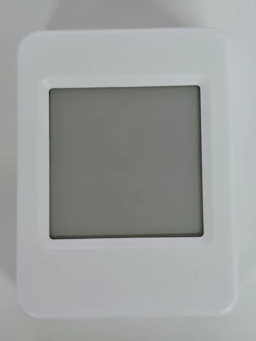
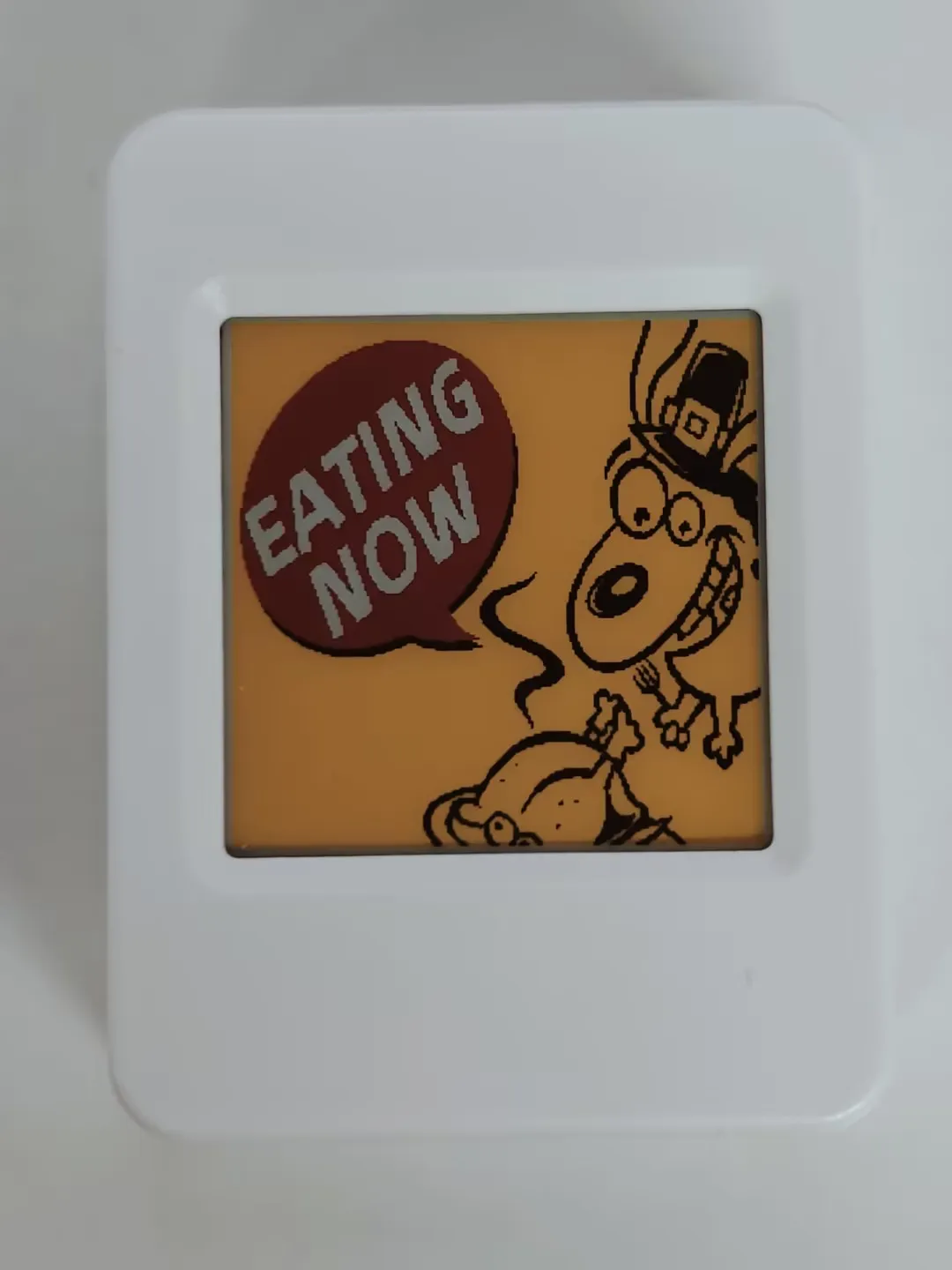
- This example is a native Arduino example for the ESP32-S3-ePaper-1.54G, demonstrating e-paper initialization, clearing the screen, displaying images, drawing basic shapes, and rendering text.
Hardware Connection
- Connect the board to the computer using a USB cable
Operation Result
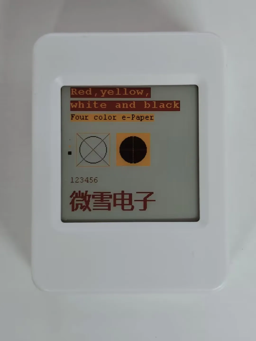
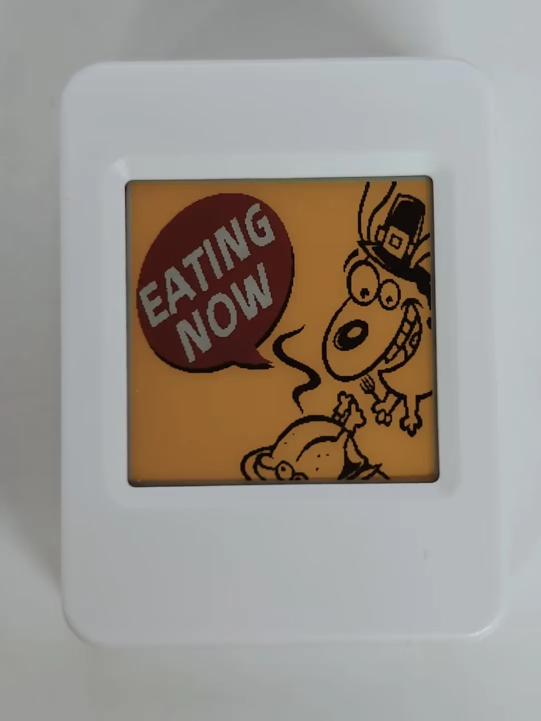
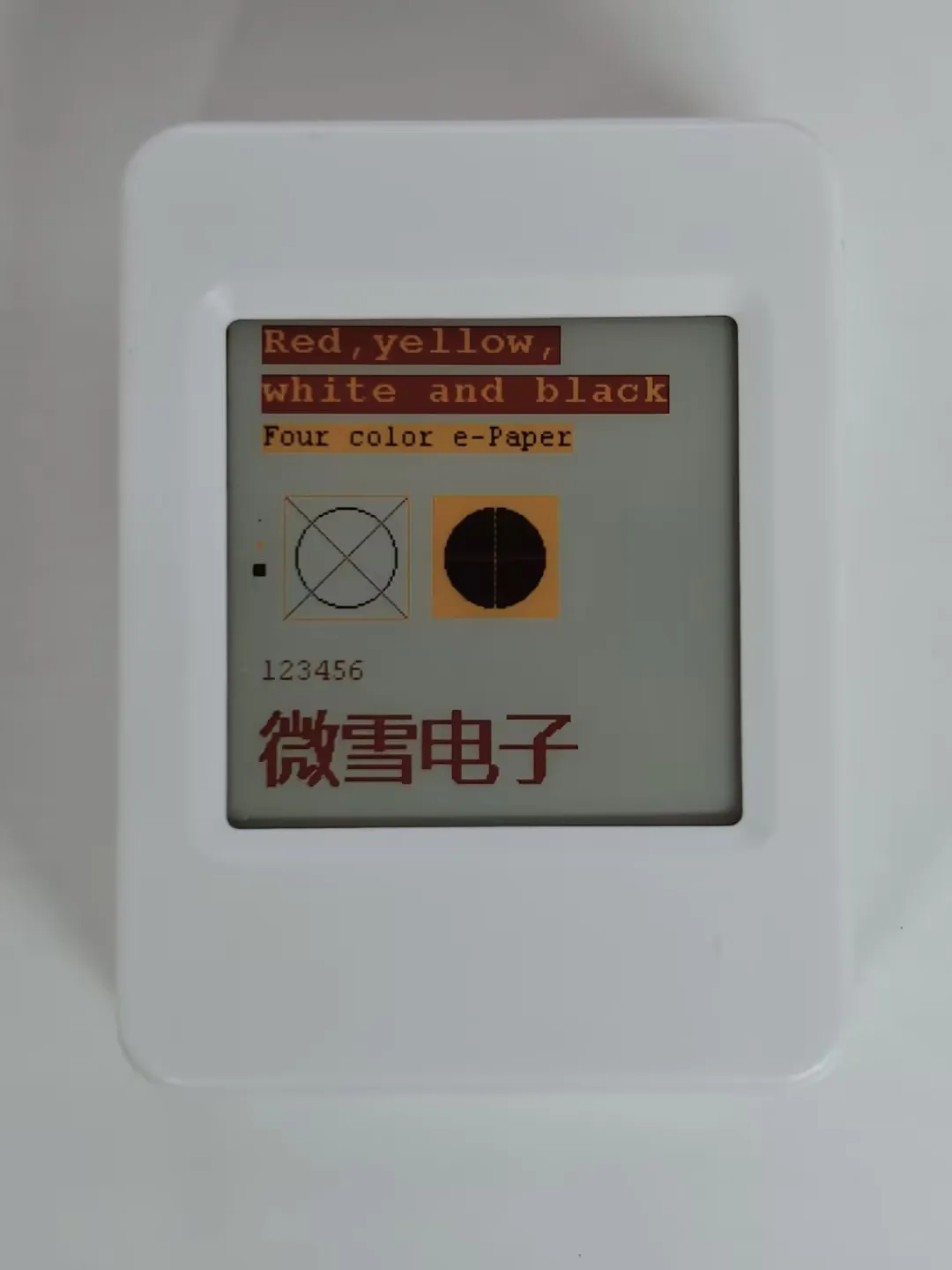
- The screen refreshes, clears, displays an image, and draws basic graphics and text.
ESP-IDF
This chapter contains the following sections. Please read as needed:
ESP-IDF Getting Started
New to ESP32 ESP-IDF development and looking to get started quickly? We have prepared a general Getting Started Tutorial for you.
- Section 1: Environment Setup
- Section 2: Running Examples
- Section 3: Creating a Project
- Section 4: Using Components
- Section 5: Debugging
- Section 6: FreeRTOS
- Section 7: Peripherals
- Section 8: Wi-Fi Programming
- Section 9: BLE Programming
Please Note: This tutorial uses the ESP32-S3-Zero as a teaching example, and all hardware code is based on its pinout. Before you start, it is recommended that you check the pinout of your development board to ensure the pin configuration is correct.
Setting Up Development Environment
For the ESP32-S3-ePaper-1.54G development board, ESP-IDF version V5.5.1 or above is required.
The following guide uses Windows as an example, demonstrating development using VS Code + the ESP-IDF extension. macOS and Linux users should refer to the official documentation.
The screenshots in this section use ESP-IDF V5.5.2 as an example. When installing, please select the ESP-IDF version that matches your board's example.
Install the ESP-IDF Development Environment
Download the installation manager from the ESP-IDF Installation Manager page. This is Espressif's latest cross-platform installer. The following steps demonstrate how to use its offline installation feature.
Click the Offline Installer tab on the page, then select Windows as the operating system and the ESP-IDF version you need (the version shown in the screenshot is for reference only — choose the version that fits your actual needs).
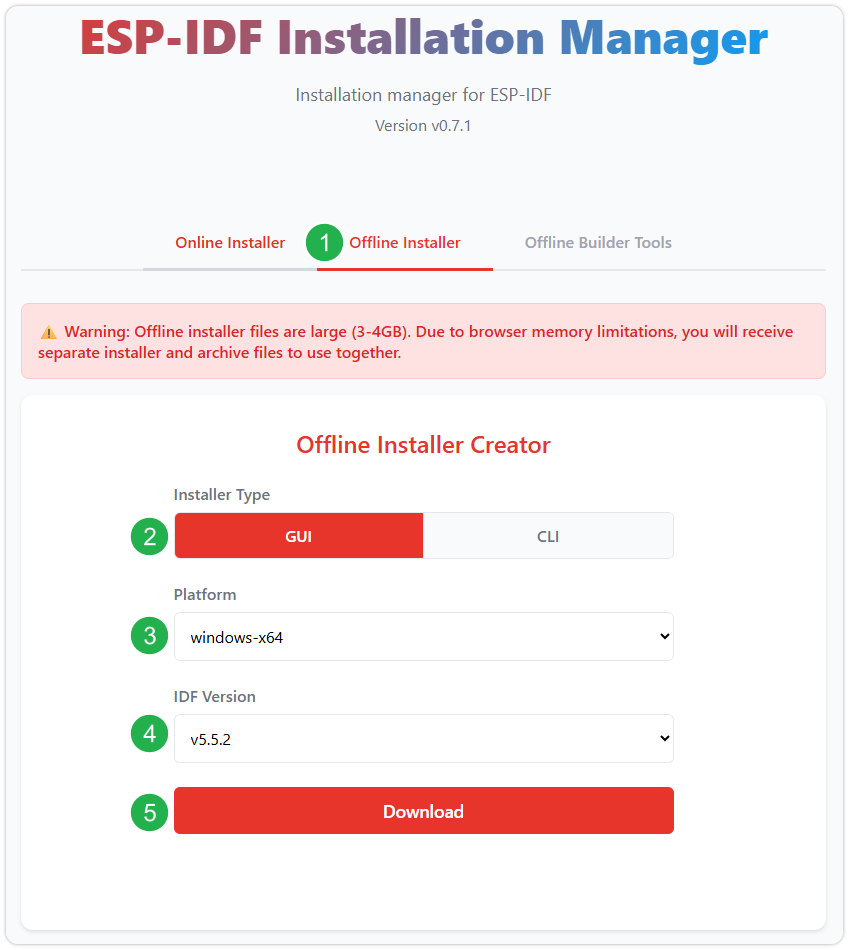
After confirming your selection, click the download button. The browser will automatically download two files: the ESP-IDF Offline Package (.zst) and the ESP-IDF Installer (.exe).
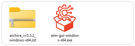
Please wait for both files to finish downloading.
Once the download is complete, double-click to run the ESP-IDF Installer (eim-gui-windows-x64.exe).
The installer will automatically detect if the offline package exists in the same directory. Click Install from archive.
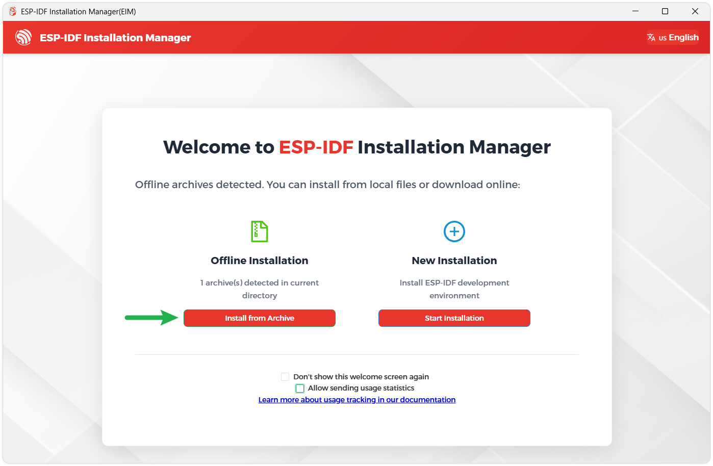
Next, select the installation path. We recommend using the default path. If you need to customize it, ensure the path does not contain Chinese characters or spaces. Click Start installation to proceed.
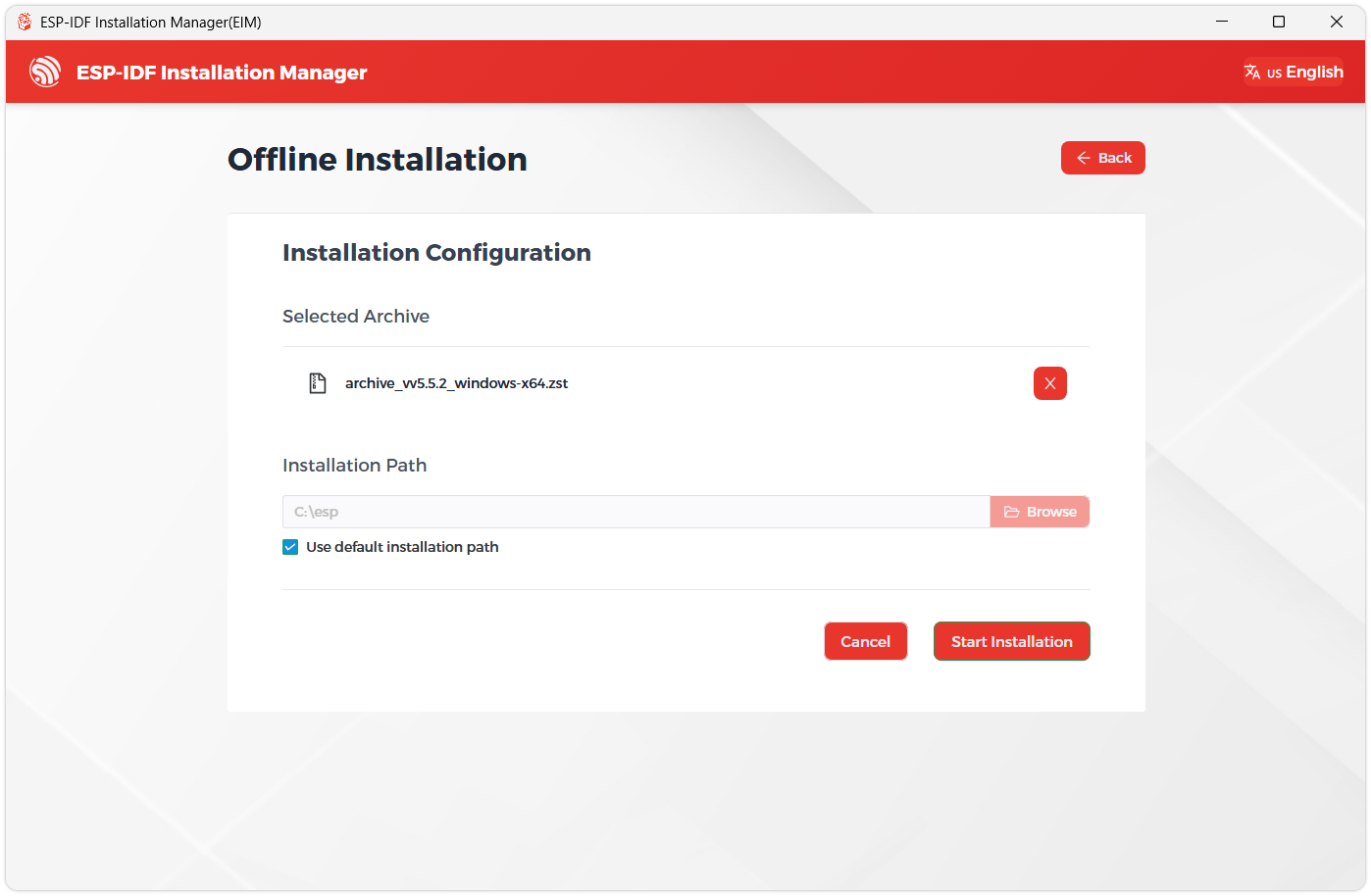
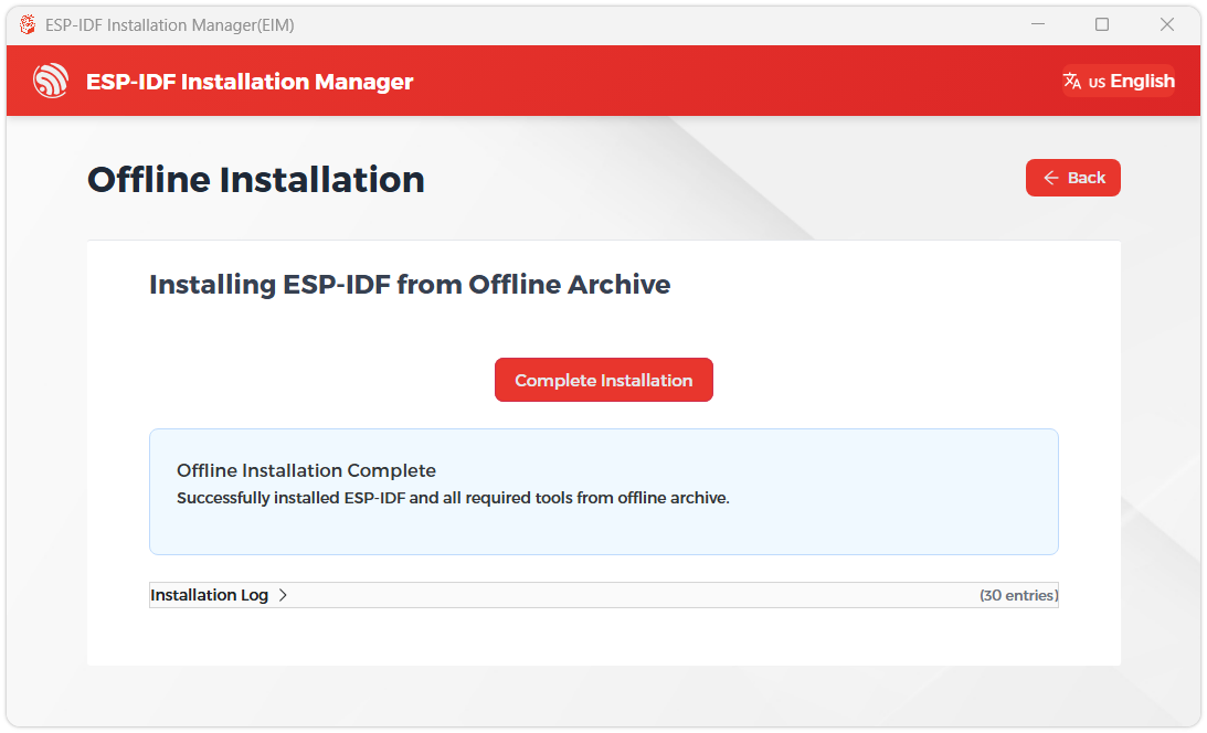
When you see the following screen, the ESP-IDF installation is successful.
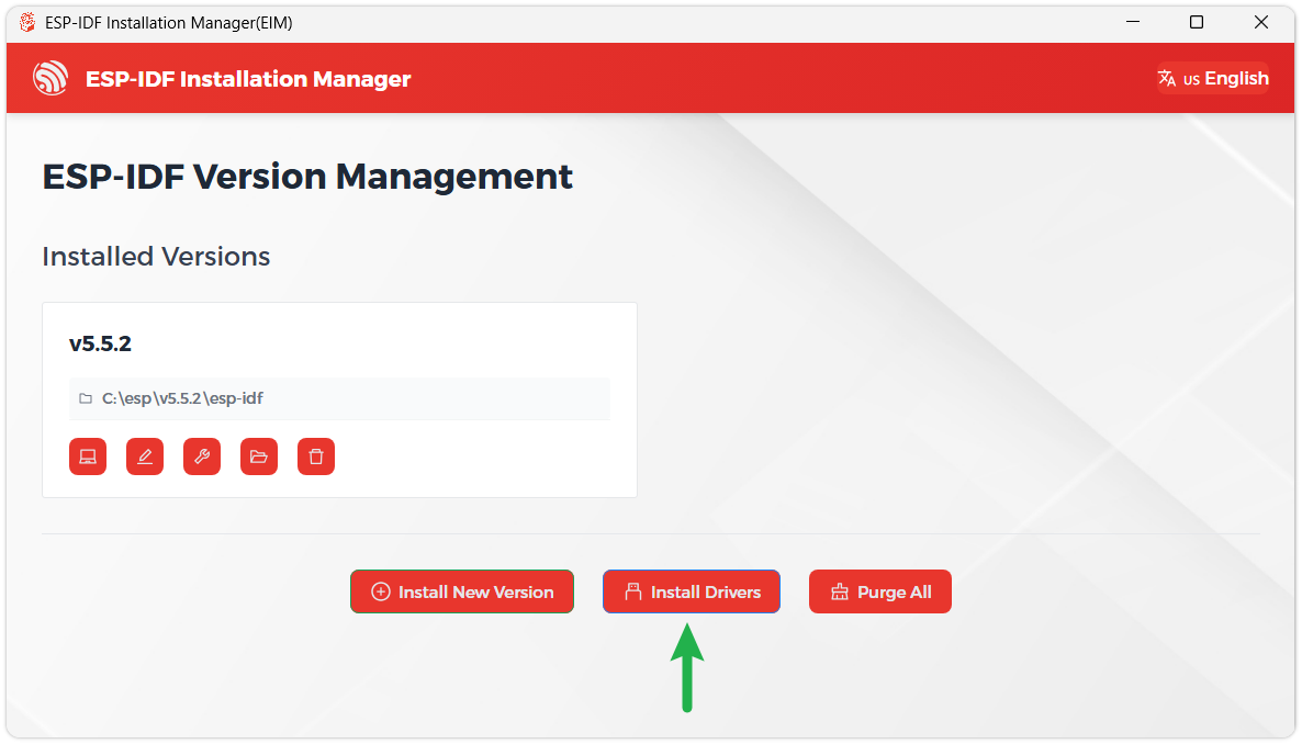
We recommend installing the drivers as well. Click Finish installation, then select Install driver.
Install Visual Studio Code and the ESP-IDF Extension
Download and install Visual Studio Code.
During installation, it is recommended to check Add "Open with Code" action to Windows Explorer file context menu to facilitate opening project folders quickly.
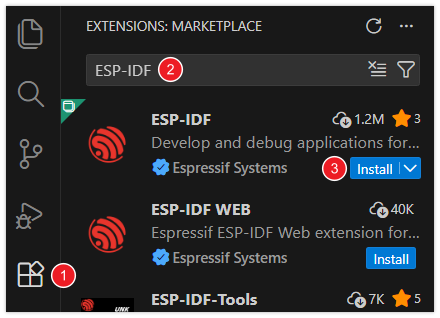
In VS Code, click the Extensions icon
 in the Activity Bar on the side (or use the shortcut Ctrl + Shift + X) to open the Extensions view.
Enter ESP-IDF in the search box, locate the ESP-IDF extension, and click Install.
For ESP-IDF extension versions ≥ 2.0, the extension will automatically detect and recognize the ESP-IDF environment installed in the previous steps, requiring no manual configuration.
Example
The ESP-IDF examples are located in the ESP-IDF directory of the example package.
| Example | Basic Program Description | Dependency Library |
|---|---|---|
| 01_ADC_Test | Get the voltage value of the lithium battery | - |
| 02_I2C_PCF85063 | Print real-time time of RTC chip | SensorLib |
| 03_I2C_STHC3 | Get data from SHTC3 temperature & humidity sensor | - |
| 04_SD_Card | Load and display TF card information | - |
| 05_WIFI_AP | Set to AP mode to obtain the IP address of the access device | - |
| 06_WIFI_STA | Set to STA mode to connect to Wi-Fi and obtain an IP address | - |
| 07_Audio_Test | Get microphone data and play it through the speaker | - |
| 08_BATT_PWR_Test | Use lithium battery power, control system power with the PWR button | - |
| 09_E_paper_test | E-paper display refresh example | - |
01_ADC_Test
Example Description
- The analog voltage connected through the GPIO is converted to digital by the ADC, and then the actual lithium battery voltage is calculated and printed to the terminal.
Hardware Connection
- Connect the board to the computer using a USB cable
Code Analysis
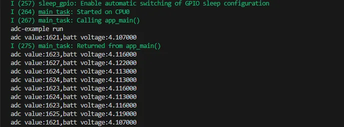
Adc_PortInit(void): Initializes ADC1, including creating an ADC one-time trigger unit and configuring channel 3 for ADC1float Adc_GetBatteryVoltage(int *data): Reads the value from ADC1 channel 3 and returns the actual voltage value.uint8_t Adc_GetBatteryLevel(void): Returns the battery percentage.void Adc_LoopTask(void *arg): Creates an ADC task that reads the ADC value and prints it to the serial port every second.
Operation Result
After the program is compiled and downloaded, you can view the printed ADC values and voltage output by opening the Serial Monitor, as shown in the following image:
02_I2C_PCF85063
Example Description
- Through the I2C protocol, initialize the PCF85063 chip, set the time, and then periodically read the time and print it to the terminal
Hardware Connection
- Connect the board to the computer using a USB cable
Code Analysis
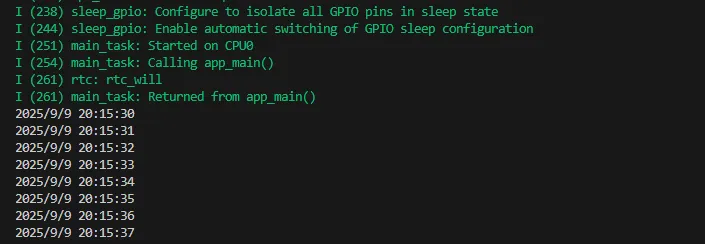
void i2c_rtc_loop_task(void *arg): Creates an RTC task to implement the RTC function, reading the clock of the RTC chip every second and outputting it to the terminal.
Operation Result
After the program is compiled and downloaded, open the serial port monitoring to see the RTC time of the printout, as shown in the following figure:
03_I2C_STHC3
Example Description
- Uses the I2C protocol to initialize and configure the SHTC3 chip, then reads and prints temperature and humidity information to the terminal every second.
Hardware Connection
- Connect the board to the computer using a USB cable
Code Analysis
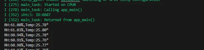
void i2c_SHTC3_loop_task(void *arg): Creates a task for the SHTC3 sensor to periodically obtain temperature and humidity data.
Operation Result
Open the serial port monitor, you can see the printed temperature and humidity data, as shown in the figure below:
04_SD_Card
Example Description
- Drive the TF card through SDMMC, and print the TF card information to the terminal after successfully mounting.
Hardware Connection
- Install a FatFs-formatted TF card into the board before powering on
Code Analysis
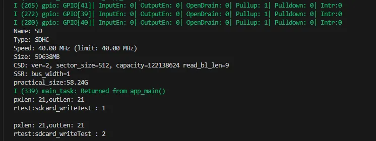
sdcard_init(void): Initializes the TF card using 1-line SDMMC mode.sdcard_loop_task(void *arg): A task to test TF card read/write functionality. You need to uncomment the#define sdcard_write_Testmacro definition.
Operation Result
Click to open the Serial Monitor device. You can see the output TF card information; practical_size indicates the actual capacity of the TF card, as shown below:
05_WIFI_AP
Example Description
- This example can set the development board as a hotspot, allowing phones or other devices in STA mode to connect to the development board.
Hardware Connection
- Connect the board to the computer using a USB cable
Code Analysis
- In the
05_WIFI_AP.inofile, locate thessidandpassword. Phones or other STA mode devices can then connect to the development board using this SSID and password.#define EXAMPLE_ESP_WIFI_SSID "waveshare_esp32"#define EXAMPLE_ESP_WIFI_PASSWORD "wav123456"
Operation Result
After flashing the program, open the serial terminal, if the device is successfully connected to the hotspot, the MAC address and IP address of the device will be output, as shown in the figure:

06_WIFI_STA
Example Description
- This example configures the development board as a STA device to connect to a router, thereby accessing the system network.
Hardware Connection
- Connect the board to the computer using a USB cable
Code Analysis
- In the file
esp_wifi_bsp.c, findssidandpassword, then modify them to the SSID and Password of an available router in your current environment.wifi_config_t wifi_config = {.sta = {.ssid = "PDCN",.password = "1234567890",},};
Operation Result
After flashing the program, open the Serial Terminal. If the device successfully connects to the hotspot, the obtained IP address will be output, as shown in the figure:

07_Audio_Test
Example Description
- This example demonstrates how to acquire microphone data and then play it back through the speaker.
Hardware Connection
- Connect the board to the computer using a USB cable
Code Analysis
i2c_master_Init(): Initializes the I2C bus.user_ui_init(): Initializes the global UI.user_button_init(): Initializes the audio interface.
Operation Result
After the program is flashed, the screen shows nothing.
TIP- Press and hold the BOOT button to enter recording mode. Speak into the MIC, then release the BOOT button to play back the recording.
- Double-click the PWR button to play a piece of music
- Click the PWR button to interrupt music playback
08_BATT_PWR_Test
Example Description
- Demonstrates how to control the system power via the PWR button when powered by the lithium battery.
Hardware Connection
- Connect the board to the computer using a USB cable
Code Analysis
user_button_init(): Initializes the buttons and their trigger events.example_button_pwr_task(void* parmeter): Task that waits for button event triggers.
Operation Result
After the program is flashed, disconnect USB power and connect a lithium battery. Press and hold the PWR button to power on. The screen shows nothing.
TIP- Press and hold the PWR button. Wait for the green LED to light up, indicating successful startup, then release the button.
- Press and hold the PWR button again, then release. The green LED turns off, indicating successful power-off.
09_E_paper_test
Example Description
- This example is a native IDF example for the ESP32-S3-ePaper-1.54G, demonstrating e-paper initialization, clearing the screen, displaying images, drawing basic shapes, and rendering text.
Hardware Connection
- Connect the board to the computer using a USB cable
Operation Result
- The screen refreshes, clears, displays an image, and draws basic graphics and text.
Resources
1. Hardware Resources
Development Board Design Files
2. Technical Manuals
ESP32-S3 Chip Official Manuals
Datasheets
3. Example
Support
Monday-Friday (9:30-6:30) Saturday (9:30-5:30)
Email: services01@spotpear.com
[Tutorial Navigation]
- Onboard Resources
- ePaper Display Specifications
- Pinout Definition
- Dimensions
- Working with Arduino
- Arduino Getting Started
- Setting Up Development Environment
- 1. Installing and Configuring the Arduino IDE
- 2. Installing Libraries
- 3. Arduino Project Parameter Settings
- Example
- ESP-IDF
- Resources
- Support