


- sales/support
Google Chat:---
- sales
+86-0755-88291180
- sales01
sales@spotpear.com
- sales02
dragon_manager@163.com
- support
tech-support@spotpear.com
- CEO-Complaints
zhoujie@spotpear.com
- Only Tech-Support
WhatsApp:13246739196
- Purchase/Shipping/Refund
WhatsApp:13424403025
- HOME
- >
- ARTICLES
- >
- Common Moudle
- >
- ESP
ESP32-C6-Touch-AMOLED-2.16 User Guide
Features
- Powered by the ESP32-C6 high-performance 32-bit RISC-V processor, with a main frequency of up to 160MHz
- Supports Wi-Fi 6, Bluetooth 5, and IEEE 802.15.4 (Zigbee 3.0 and Thread) wireless communication with excellent RF performance and onboard antenna
- Built-in 512KB HP SRAM, 16KB LP SRAM, and 320KB ROM, with external 16MB Flash
- Features a Type-C interface, enhancing user convenience and device compatibility
- Onboard 2.16inch capacitive touch high-definition AMOLED display, 480 × 480 resolution, 16.7M colors, enabling clear display of color images
- Built-in CO5300 driver chip and CST9220 capacitive touch controller chip, communicating via QSPI and I2C interfaces respectively, minimizing the use of I/O pins
- Onboard QMI8658 six-axis inertial measurement unit (3-axis accelerometer, 3-axis gyroscope) for motion posture detection, step counting, etc.
- Onboard PCF85063 RTC chip, powered by the AXP2101 with battery backup for uninterrupted operation
- Onboard KEY and BOOT side-mounted buttons for custom function development
- Onboard 3.7V MX1.25 lithium battery charge/discharge interface
- Exposed 1x I2C, 1x UART, and 1x USB solder pads for connecting external devices and debugging
- Benefits of using AXP2101 include efficient power management, support for multiple output voltages, charging and battery management functions, and optimized battery life
- Adopts AMOLED screen, featuring advantages of high contrast, wide viewing angle, rich colors, fast response, thinner design, and low power consumption, flexibility, etc.
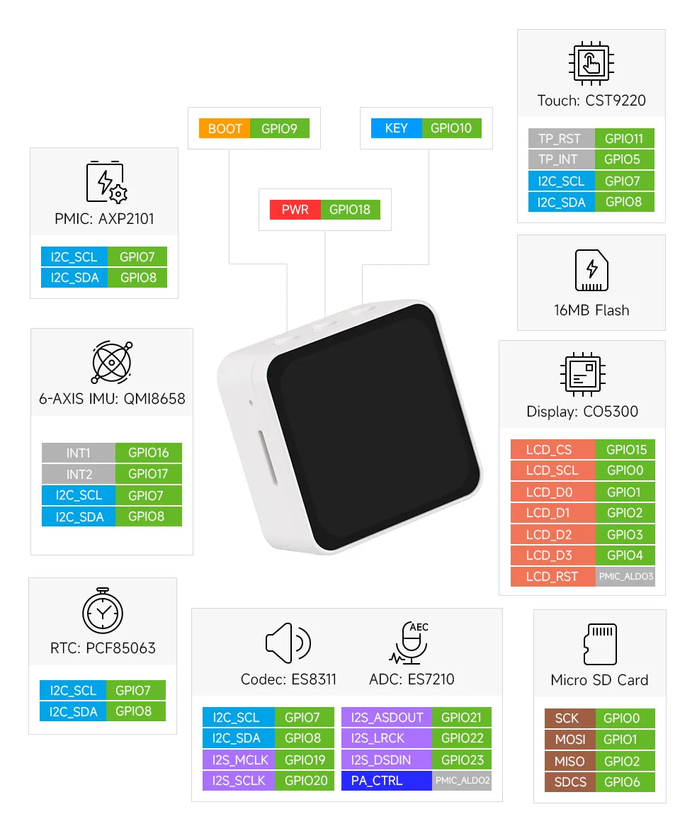
Onboard Resources
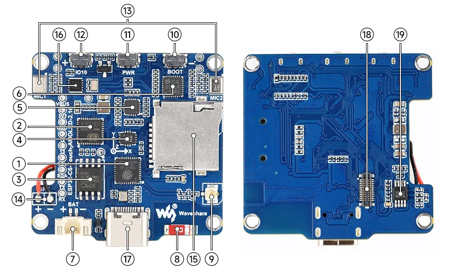
- ESP32-C6 Integrates a RISC-V single-core processor running at 160MHz, supports 2.4GHz Wi-Fi 6 and BLE 5
- AXP2101 Highly integrated power management chip
- 16MB NOR-Flash for data storage
- QMI8658 6-axis IMU includes a 3-axis gyroscope and a 3-axis accelerometer
- ES8311 Low power audio codec IC
- ES7210 ADC chip for echo cancellation circuitry
- MX1.25 Lithium Battery Header MX1.25 2PIN connector for connecting a 3.7V lithium battery, supports charging and discharging
- Onboard Chip Antenna Supports 2.4GHz Wi-Fi (802.11 b/g/n) and Bluetooth 5 (LE)
- IPEX1 Connector Switching to use the external antenna via resoldering an onboard resistor
- BOOT Button Hold the BOOT button and power on the device again to enter download mode
- PWR Button The device powers on by default when power is connected; long press to power off, short press to power on
- KEY Button Can be used for custom functions
- Dual Microphone Array Design Dual microphone array, supporting richer voice interaction functions
- 2PIN Speaker Pads Audio output signal, supports connecting an external speaker
- TF Card Slot Supports FAT32-formatted TF card for data expansion
- PCF85063 RTC clock chip, supporting time-keeping functionality
- Type-C Port ESP32‑C6 USB port for programming and log output
- Screen Interface Exclusively for connecting the screen
- Speaker Amplifier Chip Professional audio power amplifier chip providing clear and full audio output, ensuring a high-quality external playback experience
Interface Introduction
AMOLED Display Specifications
| PARAMETER | VALUE | PARAMETER | VALUE |
|---|---|---|---|
| DISPLAY PANEL | AMOLED | DISPLAY SIZE | 2.16inch |
| DISPLAY RESOLUTION | 480 × 480 pixels | DISPLAY COLOR | 16.7M |
| BRIGHTNESS | 600 cd/㎡ | CONTRAST RATIO | 100000:1 |
| COMMUNICATION INTERFACE | QSPI | DRIVER IC | CO5300 |
| TOUCH TYPE | Capacitive touch | TOUCH IC | CST9220 |
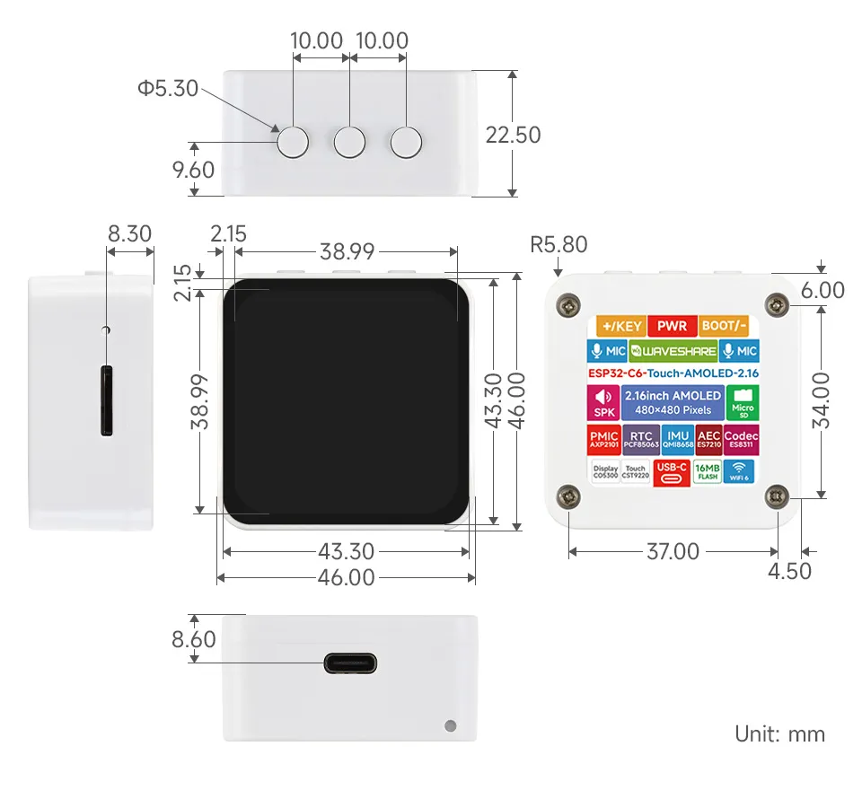
Dimensions
Working with Arduino
This chapter contains the following sections. Please read as needed:
Arduino Getting Started
New to Arduino ESP32 development and looking for a quick start? We have prepared a comprehensive Getting Started Tutorial for you.
- Section 0: Getting to Know ESP32
- Section 1: Installing and Configuring Arduino IDE
- Section 2: Arduino Basics
- Section 3: Digital Output/Input
- Section 4: Analog Input
- Section 5: Pulse Width Modulation (PWM)
- Section 6: Serial Communication (UART)
- Section 7: I2C Communication
- Section 8: SPI Communication
- Section 9: Wi-Fi Basics
- Section 10: Web Server
- Section 11: Bluetooth
- Section 12: LVGL GUI Development
- Section 13: Comprehensive Project
Note: This tutorial uses the ESP32-S3-Zero as a reference example, and all hardware code is based on its pinout. Before you start, we recommend checking the pinout of your development board to ensure the pin configuration is correct.
Setting Up Development Environment
1. Installing and Configuring Arduino IDE
For the ESP32-C6-Touch-AMOLED-2.16 development board, Arduino IDE requires arduino-esp32 version v3.3.0 or later.
Please refer to the tutorial Installing and Configuring Arduino IDE to download and install the Arduino IDE and add ESP32 support.
2. Installing Libraries
- When installing Arduino libraries, there are typically two methods: Install Online and Install Offline. If the library installation requires Install Offline, you must use the provided library file.
- For most libraries, users can easily search for and install them via the Arduino IDE's online Library Manager. However, some open-source or custom libraries are not synchronized to the Arduino Library Manager and therefore cannot be found through online search. In this case, users can only install these libraries manually via offline methods.
- The sample program package for the ESP32-C6-Touch-AMOLED-2.16 development board can be downloaded from here. The
Arduino\librariesdirectory within the package already contains all the library files required for this tutorial.
| Library/File Name | Description | Version | Installation Method |
|---|---|---|---|
| LVGL | Graphical library | v8.* / v9.* | "Install Offline" |
| SensorLib | Sensor control library | v0.3.1 | "Install Online" or "Install Offline" |
There are strong dependencies between versions of LVGL and its driver libraries. For example, a driver written for LVGL v8 may not be compatible with LVGL v9. To ensure that the examples can be reproduced reliably, it is recommended to use the specific versions listed in the table above. Mixing different versions of libraries may lead to compilation failures or runtime errors.
3. Arduino Project Parameter Settings
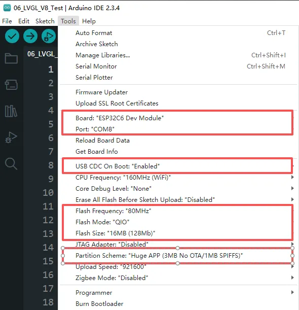
Demo
The Arduino demos are located in the Arduino/examples directory of the demo package.
| Demo | Basic Program Description | Dependency Library |
|---|---|---|
| 01_ADC_Test | Get the voltage value of the lithium battery | - |
| 02_I2C_PCF85063 | Print real-time time of RTC chip | SensorLib |
| 03_I2C_QMI8658 | Print the raw data from IMU | SensorLib |
| 04_SD_Card | Load and display the information of the TF card | - |
| 05_WIFI_AP | Set to AP mode to obtain the IP address of the access device | - |
| 06_WIFI_STA | Set to STA mode to connect to WiFi and obtain an IP address | - |
| 07_BATT_PWR_Test | Control power via the PWR button when powered solely by the lithium battery | - |
| 08_Audio_Test | Play the sound recorded by the microphone through the speaker | - |
| 09_LVGL_V8_Test | LVGL V8 demo | LVGL V8.* |
| 10_LVGL_V9_Test | LVGL V9 demo | LVGL V9.* |
01_AXP2101_Test
Demo Description
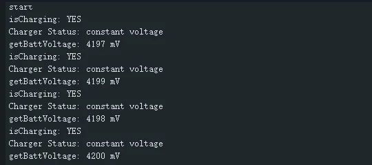
- Obtain power information by driving the AXP2101 and print it to the terminal.
Hardware Connection
- Connect the board to the computer using a USB cable
Code Analysis
axp2101.setDC1Voltage(3300);      //Set DCDC1 voltage to 3.3V
axp2101.setALDO1Voltage(3300);    //Set DCDC1 voltage to 3.3V
axp2101.setALDO2Voltage(3300);    //Set DCDC1 voltage to 3.3V
axp2101.setALDO3Voltage(3300);    //Set DCDC1 voltage to 3.3V
axp2101.setALDO4Voltage(3300);    //Set DCDC1 voltage to 3.3V
axp2101.setPrechargeCurr(XPOWERS_AXP2101_PRECHARGE_50MA);     //Set precharge current to 50mA
axp2101.setChargerConstantCurr(XPOWERS_AXP2101_CHG_CUR_500MA);  //Set constant charging current to 500mA
axp2101.setChargerTerminationCurr(XPOWERS_AXP2101_CHG_ITERM_50MA);  //Set termination charging current to 50mA
axp2101.getBattVoltage();   //Get lithium battery voltage
Operation Result
After compiling and downloading the program, open the Serial Monitor to see the printed power information, as shown in the figure below:
02_I2C_QMI8658
Demo Description
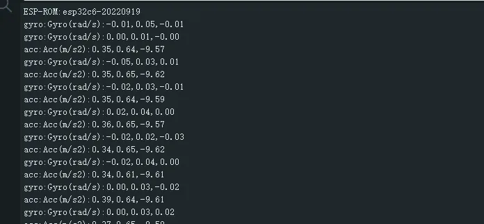
- Obtain attitude information by driving the QMI8658 and print it to the terminal.
Hardware Connection
- Connect the board to the computer using a USB cable
Code Analysis
qmi8658_set_accel_range(&qmi8658, QMI8658_ACCEL_RANGE_8G); // Set accelerometer range to ±8G (G = gravitational acceleration)
qmi8658_set_accel_odr(&qmi8658, QMI8658_ACCEL_ODR_1000HZ); // Set accelerometer output data rate to 1000Hz
qmi8658_set_gyro_range(&qmi8658, QMI8658_GYRO_RANGE_512DPS); // Set gyroscope range to ±512°/s
qmi8658_set_gyro_odr(&qmi8658, QMI8658_GYRO_ODR_1000HZ); // Set gyroscope output data rate to 1000Hz
qmi8658_set_accel_unit_mps2(&qmi8658, true); // Set accelerometer output unit to m/s²
qmi8658_set_gyro_unit_rads(&qmi8658, true); // Set gyroscope output unit to rad/s
qmi8658_set_display_precision(&qmi8658, 4); // Set output/print precision to 4 decimal places
Operation Result
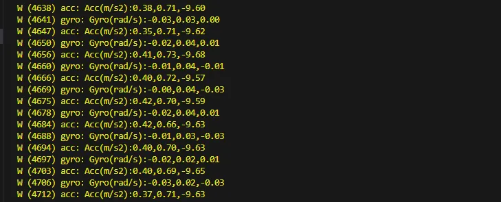
After compiling and downloading the program, open the Serial Monitor to see the printed attitude information, as shown in the figure below:
03_I2C_QMI8658
Demo Description
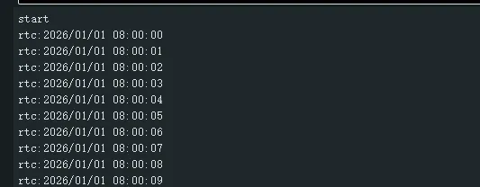
- Set and obtain time by driving the PCF85063, and print it to the terminal.
Hardware Connection
- Connect the board to the computer using a USB cable
Code Analysis
pcf85063a_datetime_t datatime = {
  .year = 2026,
  .month = 1,
  .day = 1,
  .hour = 8,
  .min = 0,
  .sec = 0
};
pcf85063a_set_time_date(&pcf85063, datatime);  /*Set start time 2026/1/1 08:00:00*/
pcf85063a_get_time_date(&pcf85063, &datatime);  /*Get current time*/
Operation Result
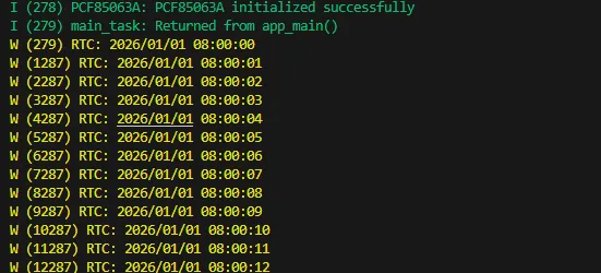
After the program is compiled and downloaded, open the serial port monitoring to see the RTC time of the printout, as shown in the following figure:
04_SD_Card
Demo Description
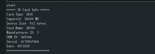
- Drive the TF card using SDSPI and print the TF card information to the terminal.
Hardware Connection
- Connect the board to the computer using a USB cable
Code Analysis
esp_vfs_fat_sdspi_mount(SdName_, &host, &slot_config, &mount_config, &sdCardHead);  //Mount sdcard to fatfs filesystem
int SDPort_WriteFile(const char *path, const void *data, size_t data_len);  //Write data to file
int SDPort_ReadFile(const char *path, uint8_t *buffer, size_t *outLen);  //Read data from file
int SDPort_ReadOffset(const char *path, void *buffer, size_t len, size_t offset);  //Read data from file with offset
int SDPort_WriteOffset(const char *path, const void *data, size_t len, bool append);  //Write data to file with offset
Operation Result
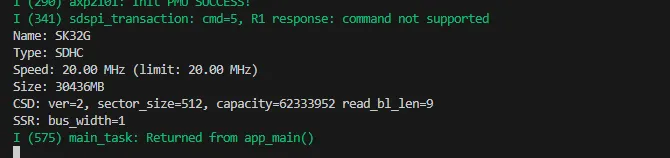
- After compiling and downloading the program, open the Serial Monitor to see the printed TF card information, as shown in the figure below:
05_WIFI_STA
Demo Description
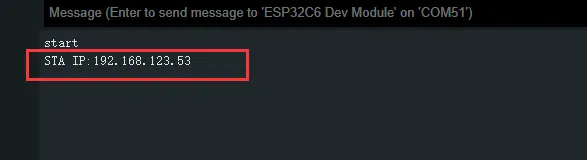
- Set the development board to Wi-Fi STA mode, connect to an AP router, and print the obtained IP address to the terminal.
Hardware Connection
- Connect the board to the computer using a USB cable
Code Analysis
nvs_flash_init();                                    // Initialize NVS (non-volatile storage) for saving Wi-Fi configuration data
esp_netif_init();                                    // Initialize TCP/IP stack, required for network communication
esp_event_loop_create_default();                     // Create default event loop for system event distribution (e.g., Wi-Fi events)
esp_netif_create_default_wifi_sta();                 // Create default Wi-Fi STA (Station) interface for connecting to a router
esp_netif_create_default_wifi_ap();                  // Create default Wi-Fi AP (Access Point) interface for providing a hotspot
strcpy((char*)sta_config.sta.ssid, "ESP32_STA");     // Set the router's SSID
strcpy((char*)sta_config.sta.password, "12345678");  // Set the router's password
esp_wifi_set_mode(WIFI_MODE_STA);                    // Set ESP32 Wi-Fi mode
Operation Result
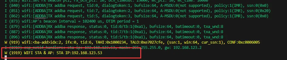
- After compiling and downloading the program, open the Serial Monitor to see the printed IP address, as shown in the figure below:
06_WIFI_AP
Demo Description
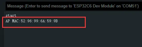
- Set the development board to Wi-Fi AP mode. Other STA devices can connect to this AP, and upon successful connection, the device's MAC address will be printed to the terminal.
Hardware Connection
- Connect the board to the computer using a USB cable
Code Analysis
nvs_flash_init();                                      // Initialize NVS (non-volatile storage) for saving Wi-Fi configuration data
esp_netif_init();                                      // Initialize TCP/IP stack, required for network communication
esp_event_loop_create_default();                       // Create default event loop for system event distribution (e.g., Wi-Fi events)
esp_netif_create_default_wifi_sta();                   // Create default Wi-Fi STA (Station) interface for connecting to a router
esp_netif_create_default_wifi_ap();                    // Create default Wi-Fi AP (Access Point) interface for providing a hotspot
strcpy((char*)ap_config.ap.ssid, "ESP32_AP");          // Set the AP's SSID to "ESP32_AP"
strcpy((char*)ap_config.ap.password, "12345678");      // et the AP's password to "12345678" (at least 8 characters)
ap_config.ap.max_connection = 4;                       // Set a maximum of 4 devices to connect simultaneously
ap_config.ap.authmode = WIFI_AUTH_WPA_WPA2_PSK;        // Set authentication mode to WPA/WPA2 PSK (password authentication)
esp_wifi_set_mode(WIFI_MODE_AP);                       // Set Wi-Fi mode to AP mode (hotspot only)
esp_wifi_set_config(WIFI_IF_AP, &ap_config);           // Apply the AP configuration to enable the Wi-Fi hotspot
Operation Result
- After compiling and downloading the program, open the Serial Monitor to see the printed MAC address, as shown in the figure below:
07_Audio_Test
Demo Description
- Implement recording and playback by driving the ES8311 and ES7210 Codec chips.
Hardware Connection
- Connect the board to the computer using a USB cable
Code Analysis
esp_err_t play_pcm_from_spiffs(uint8_t *play_buf, const char *file_path,bool *Music_flag); // Read audio data from the spiffs filesystem and play it
void fac_play_read_storage(uint8_t *play_buf); // Read binary recording data from the filesystem and play it
void fac_rec_write_storage(uint8_t *rec_buf,size_t max_size); // Save recorded data to spiffs
Operation Result
After compiling and downloading the program, the display on the development board will appear as shown below:
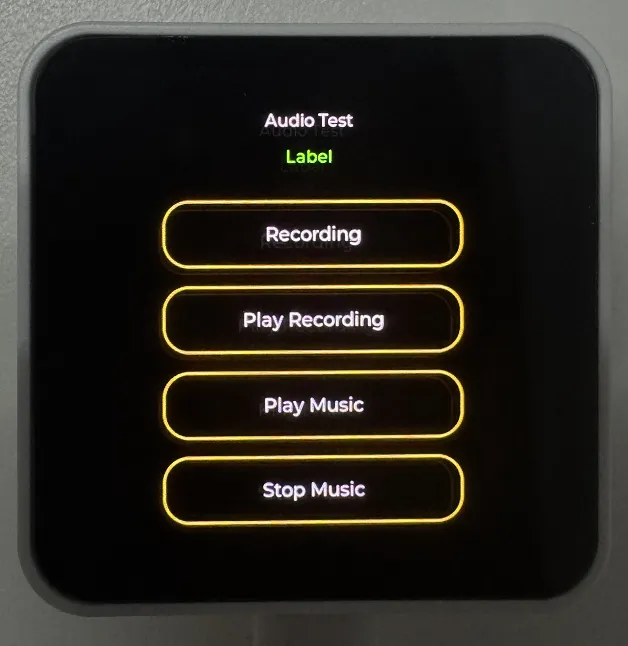 TIP
TIP- Click Recording to record; recording lasts 3 seconds
- Click Play Recording to play the recording
- Click Play Music to play music
- Click Stop Music to pause music
08_LVGL_V8_Test
Demo Description
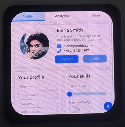
- By porting LVGL V8, this helps users quickly get started with UI design.
Hardware Connection
- Connect the board to the computer using a USB cable
Code Analysis
#define Brightness_Test_EN  1 // Set to 0 to disable backlight test, default is 1
Custom_PmicPortInit(&user_i2cbus,0x34); // Initialize power IC
user_display = new DisplayPort(user_i2cbus,480,480); // Initialize the screen
user_display->DisplayPort_TouchInit(); // Initialize touch
Lvgl_PortInit(*user_display); // Initialize LVGL interface
Operation Result
- After compiling and downloading the program, the display on the development board will appear as shown below:

09_LVGL_V9_Test
Demo Description
- By porting LVGL V9, this helps users quickly get started with UI design.
Hardware Connection
- Connect the board to the computer using a USB cable
Code Analysis
#define Brightness_Test_EN  1 // Set to 0 to disable backlight test, default is 1
Custom_PmicPortInit(&user_i2cbus,0x34); // Initialize power IC
user_display = new DisplayPort(user_i2cbus,480,480); // Initialize the screen
user_display->DisplayPort_TouchInit(); // Initialize touch
Lvgl_PortInit(*user_display); // Initialize LVGL interface
Operation Result
- After compiling and downloading the program, the display on the development board will appear as shown below:
ESP-IDF
This chapter contains the following sections. Please read as needed:
ESP-IDF Getting Started
New to ESP32 ESP-IDF development and looking to get started quickly? We have prepared a general Getting Started Tutorial for you.
- Section 1: Environment Setup
- Section 2: Running Examples
- Section 3: Creating a Project
- Section 4: Using Components
- Section 5: Debugging
- Section 6: FreeRTOS
- Section 7: Peripherals
- Section 8: Wi-Fi Programming
- Section 9: BLE Programming
Please Note: This tutorial uses the ESP32-S3-Zero as a teaching example, and all hardware code is based on its pinout. Before you start, it is recommended that you check the pinout of your development board to ensure the pin configuration is correct.
Setting Up Development Environment
For the ESP32-C6-Touch-AMOLED-2.16 development board, development is based on ESP-IDF V5.5.2. It is recommended to use the same version for testing and development, as other versions may have compatibility issues.
The following guide uses Windows as an example, demonstrating development using VS Code + the ESP-IDF extension. macOS and Linux users should refer to the official documentation.
Install the ESP-IDF Development Environment
Download the installation manager from the ESP-IDF Installation Manager page. This is Espressif's latest cross-platform installer. The following steps demonstrate how to use its offline installation feature.
Click the Offline Installer tab on the page, then select Windows as the operating system and choose your desired version from the filter bar.
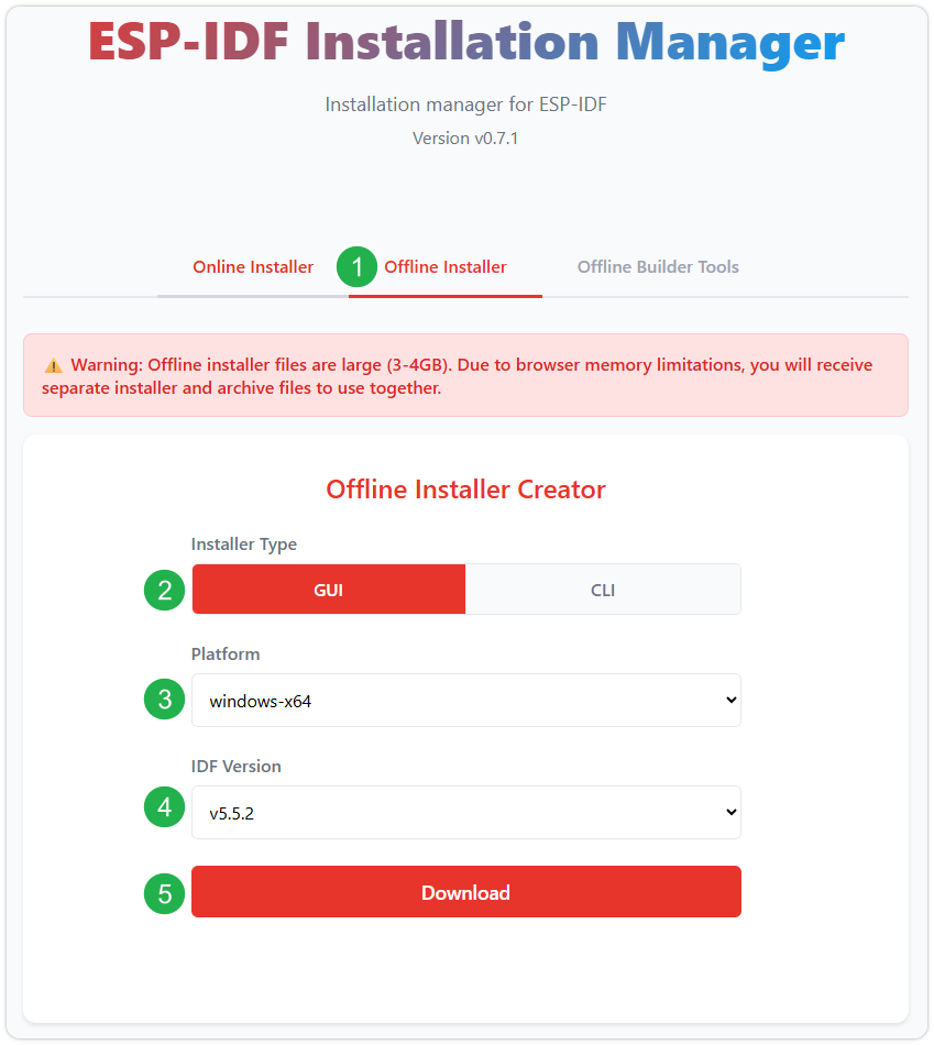
After confirming your selection, click the download button. The browser will automatically download two files: the ESP-IDF Offline Package (.zst) and the ESP-IDF Installer (.exe).
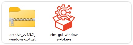
Please wait for both files to finish downloading.
Once the download is complete, double-click to run the ESP-IDF Installer (eim-gui-windows-x64.exe).
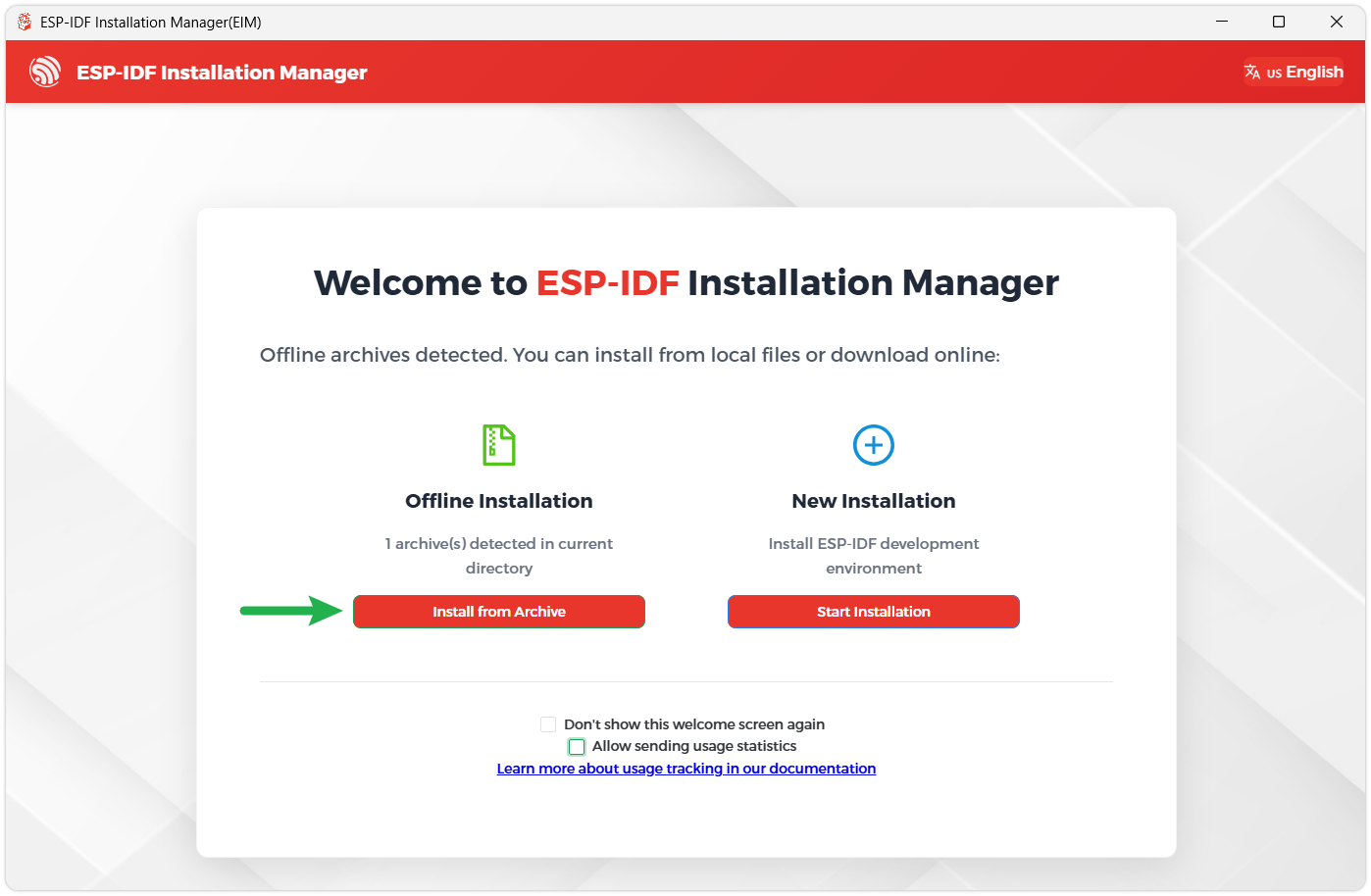
The installer will automatically detect if the offline package exists in the same directory. Click Install from archive.
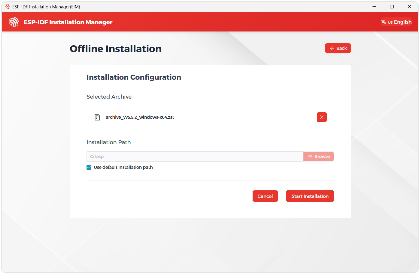
Next, select the installation path. We recommend using the default path. If you need to customize it, ensure the path does not contain Chinese characters or spaces. Click Start installation to proceed.
When you see the following screen, the ESP-IDF installation is successful.
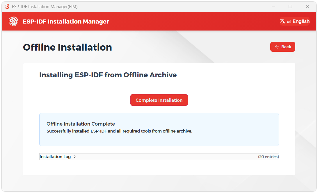
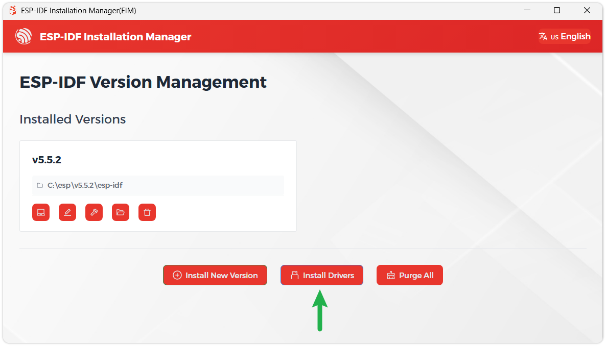
We recommend installing the drivers as well. Click Finish installation, then select Install driver.
Install Visual Studio Code and the ESP-IDF Extension
Download and install Visual Studio Code.
During installation, it is recommended to check Add "Open with Code" action to Windows Explorer file context menu to facilitate opening project folders quickly.
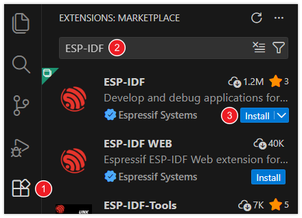
In VS Code, click the Extensions icon
 in the Activity Bar on the side (or use the shortcut Ctrl + Shift + X) to open the Extensions view.
Enter ESP-IDF in the search box, locate the ESP-IDF extension, and click Install.
For ESP-IDF extension versions ≥ 2.0, the extension will automatically detect and recognize the ESP-IDF environment installed in the previous steps, requiring no manual configuration.
Demo
The ESP-IDF demos are located in the ESP-IDF directory of the demo package.
| Demo | Basic Program Description | Dependency Library |
|---|---|---|
| 01_AXP2101_Test | Drive the AXP2101 power management chip to obtain relevant power information | - |
| 02_I2C_QMI8658 | Print raw attitude data from the QMI chip | - |
| 03_I2C_PCF85063 | Print real-time time from the RTC chip | - |
| 04_SD_Card | Load and display TF card information | - |
| 05_WIFI_STA | Set to STA mode, can connect to AP and obtain IP address | - |
| 06_WIFI_AP | Set to AP mode to obtain the IP address of the access device | - |
| 07_Audio_Test | Play the sound recorded by the microphone through the speaker | - |
| 08_LVGL_V8_Test | LVGL V8 demo | LVGL V8.* |
| 09_LVGL_V9_Test | LVGL V9 demo | LVGL V9.* |
| 10_FactoryProgram | Comprehensive demo | LVGL V9.* |
01_AXP2101_Test
Demo Description
- Obtain power information by driving the AXP2101 and print it to the terminal.
Hardware Connection
- Connect the board to the computer using a USB cable
Code Analysis
axp2101.setDC1Voltage(3300);      //Set DCDC1 voltage to 3.3V
axp2101.setALDO1Voltage(3300);    //Set DCDC1 voltage to 3.3V
axp2101.setALDO2Voltage(3300);    //Set DCDC1 voltage to 3.3V
axp2101.setALDO3Voltage(3300);    //Set DCDC1 voltage to 3.3V
axp2101.setALDO4Voltage(3300);    //Set DCDC1 voltage to 3.3V
axp2101.setPrechargeCurr(XPOWERS_AXP2101_PRECHARGE_50MA);     //Set precharge current to 50mA
axp2101.setChargerConstantCurr(XPOWERS_AXP2101_CHG_CUR_500MA);  //Set constant charging current to 500mA
axp2101.setChargerTerminationCurr(XPOWERS_AXP2101_CHG_ITERM_50MA);  //Set termination charging current to 50mA
axp2101.getBattVoltage();   //Get lithium battery voltage
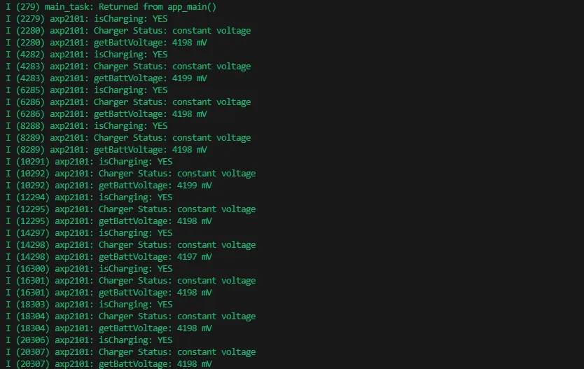
Operation Result
After compiling and downloading the program, open the Serial Monitor to see the printed power information, as shown in the figure below:
02_I2C_QMI8658
Demo Description
- Obtain attitude information by driving the QMI8658 and print it to the terminal.
Hardware Connection
- Connect the board to the computer using a USB cable
Code Analysis
qmi8658_set_accel_range(&qmi8658, QMI8658_ACCEL_RANGE_8G); // Set accelerometer range to ±8G (G = gravitational acceleration)
qmi8658_set_accel_odr(&qmi8658, QMI8658_ACCEL_ODR_1000HZ); // Set accelerometer output data rate to 1000Hz
qmi8658_set_gyro_range(&qmi8658, QMI8658_GYRO_RANGE_512DPS); // Set gyroscope range to ±512°/s
qmi8658_set_gyro_odr(&qmi8658, QMI8658_GYRO_ODR_1000HZ); // Set gyroscope output data rate to 1000Hz
qmi8658_set_accel_unit_mps2(&qmi8658, true); // Set accelerometer output unit to m/s²
qmi8658_set_gyro_unit_rads(&qmi8658, true); // Set gyroscope output unit to rad/s
qmi8658_set_display_precision(&qmi8658, 4); // Set output/print precision to 4 decimal places
Operation Result
After compiling and downloading the program, open the Serial Monitor to see the printed attitude information, as shown in the figure below:
03_I2C_QMI8658
Demo Description
- Set and obtain time by driving the PCF85063, and print it to the terminal.
Hardware Connection
- Connect the board to the computer using a USB cable
Code Analysis
pcf85063a_datetime_t datatime = {
  .year = 2026,
  .month = 1,
  .day = 1,
  .hour = 8,
  .min = 0,
  .sec = 0
};
pcf85063a_set_time_date(&pcf85063, datatime);  /*Set start time 2026/1/1 08:00:00*/
pcf85063a_get_time_date(&pcf85063, &datatime);  /*Get current time*/
Operation Result
After the program is compiled and downloaded, open the serial port monitoring to see the RTC time of the printout, as shown in the following figure:
04_SD_Card
Demo Description
- Drive the TF card using SDSPI and print the TF card information to the terminal.
Hardware Connection
- Connect the board to the computer using a USB cable
Code Analysis
esp_vfs_fat_sdspi_mount(SdName_, &host, &slot_config, &mount_config, &sdCardHead);  //Mount sdcard to fatfs filesystem
int SDPort_WriteFile(const char *path, const void *data, size_t data_len);  //Write data to file
int SDPort_ReadFile(const char *path, uint8_t *buffer, size_t *outLen);  //Read data from file
int SDPort_ReadOffset(const char *path, void *buffer, size_t len, size_t offset);  //Read data from file with offset
int SDPort_WriteOffset(const char *path, const void *data, size_t len, bool append);  //Write data to file with offset
Operation Result
- After compiling and downloading the program, open the Serial Monitor to see the printed TF card information, as shown in the figure below:
05_WIFI_STA
Demo Description
- Set the development board to Wi-Fi STA mode, connect to an AP router, and print the obtained IP address to the terminal.
Hardware Connection
- Connect the board to the computer using a USB cable
Code Analysis
nvs_flash_init();                                    // Initialize NVS (non-volatile storage) for saving Wi-Fi configuration data
esp_netif_init();                                    // Initialize TCP/IP stack, required for network communication
esp_event_loop_create_default();                     // Create default event loop for system event distribution (e.g., Wi-Fi events)
esp_netif_create_default_wifi_sta();                 // Create default Wi-Fi STA (Station) interface for connecting to a router
esp_netif_create_default_wifi_ap();                  // Create default Wi-Fi AP (Access Point) interface for providing a hotspot
strcpy((char*)sta_config.sta.ssid, "ESP32_STA");     // Set the router's SSID
strcpy((char*)sta_config.sta.password, "12345678");  // Set the router's password
esp_wifi_set_mode(WIFI_MODE_STA);                    // Set ESP32 Wi-Fi mode
Operation Result
- After compiling and downloading the program, open the Serial Monitor to see the printed IP address, as shown in the figure below:
06_WIFI_AP
Demo Description
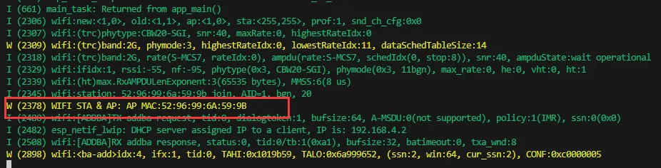
- Set the development board to Wi-Fi AP mode. Other STA devices can connect to this AP, and upon successful connection, the device's MAC address will be printed to the terminal.
Hardware Connection
- Connect the board to the computer using a USB cable
Code Analysis
nvs_flash_init();                                      // Initialize NVS (non-volatile storage) for saving Wi-Fi configuration data
esp_netif_init();                                      // Initialize TCP/IP stack, required for network communication
esp_event_loop_create_default();                       // Create default event loop for system event distribution (e.g., Wi-Fi events)
esp_netif_create_default_wifi_sta();                   // Create default Wi-Fi STA (Station) interface for connecting to a router
esp_netif_create_default_wifi_ap();                    // Create default Wi-Fi AP (Access Point) interface for providing a hotspot
strcpy((char*)ap_config.ap.ssid, "ESP32_AP");          // Set the AP's SSID to "ESP32_AP"
strcpy((char*)ap_config.ap.password, "12345678");      // et the AP's password to "12345678" (at least 8 characters)
ap_config.ap.max_connection = 4;                       // Set a maximum of 4 devices to connect simultaneously
ap_config.ap.authmode = WIFI_AUTH_WPA_WPA2_PSK;        // Set authentication mode to WPA/WPA2 PSK (password authentication)
esp_wifi_set_mode(WIFI_MODE_AP);                       // Set Wi-Fi mode to AP mode (hotspot only)
esp_wifi_set_config(WIFI_IF_AP, &ap_config);           // Apply the AP configuration to enable the Wi-Fi hotspot
Operation Result
- After compiling and downloading the program, open the Serial Monitor to see the printed MAC address, as shown in the figure below:
07_Audio_Test
Demo Description
- Implement recording and playback by driving the ES8311 and ES7210 Codec chips.
Hardware Connection
- Connect the board to the computer using a USB cable
Code Analysis
esp_err_t play_pcm_from_spiffs(uint8_t *play_buf, const char *file_path,bool *Music_flag); // Read audio data from the spiffs filesystem and play it
void fac_play_read_storage(uint8_t *play_buf); // Read binary recording data from the filesystem and play it
void fac_rec_write_storage(uint8_t *rec_buf,size_t max_size); // Save recorded data to spiffs
Operation Result
After compiling and downloading the program, the display on the development board will appear as shown below:
 TIP
TIP- Click Recording to record; recording lasts 3 seconds
- Click Play Recording to play the recording
- Click Play Music to play music
- Click Stop Music to pause music
08_LVGL_V8_Test
Demo Description
- By porting LVGL V8, this helps users quickly get started with UI design.
Hardware Connection
- Connect the board to the computer using a USB cable
Code Analysis
#define Brightness_Test_EN  1 // Set to 0 to disable backlight test, default is 1
Custom_PmicPortInit(&user_i2cbus,0x34); // Initialize power IC
user_display = new DisplayPort(user_i2cbus,480,480); // Initialize the screen
user_display->DisplayPort_TouchInit(); // Initialize touch
Lvgl_PortInit(*user_display); // Initialize LVGL interface
Operation Result
- After compiling and downloading the program, the display on the development board will appear as shown below:

09_LVGL_V9_Test
Demo Description
- By porting LVGL V9, this helps users quickly get started with UI design.
Hardware Connection
- Connect the board to the computer using a USB cable
Code Analysis
#define Brightness_Test_EN  1 // Set to 0 to disable backlight test, default is 1
Custom_PmicPortInit(&user_i2cbus,0x34); // Initialize power IC
user_display = new DisplayPort(user_i2cbus,480,480); // Initialize the screen
user_display->DisplayPort_TouchInit(); // Initialize touch
Lvgl_PortInit(*user_display); // Initialize LVGL interface
Operation Result
- After compiling and downloading the program, the display on the development board will appear as shown below:

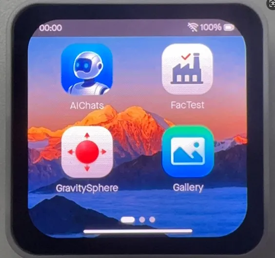
10_FactoryProgram
Demo Description
- Factory firmware. Users can flash the provided factory firmware to quickly get to know the development board.
Hardware Connection
- Connect the board to the computer using a USB cable
Operation Result
After flashing the factory firmware and restarting, the display on the development board will appear as shown below:
Resources
1. Hardware Resources
Development Board Design Files
2. Technical Manuals
ESP32-C6 Chip Official Manuals
Datasheets
3. Demo
Support
Monday-Friday (9:30-6:30) Saturday (9:30-5:30)
Email: services01@spotpear.com
[Tutorial Navigation]
- Features
- Onboard Resources
- Interface Introduction
- AMOLED Display Specifications
- Dimensions
- Working with Arduino
- Arduino Getting Started
- Setting Up Development Environment
- 1. Installing and Configuring Arduino IDE
- 2. Installing Libraries
- 3. Arduino Project Parameter Settings
- Demo
- ESP-IDF
- Resources
- Support