




- sales/support
Google Chat:---
- sales
+86-0755-88291180
- sales01
sales@spotpear.com
- sales02
dragon_manager@163.com
- support
tech-support@spotpear.com
- CEO-Complaints
zhoujie@spotpear.com
- Only Tech-Support
WhatsApp:13246739196
- Purchase/Shipping/Refund
WhatsApp:13424403025
- HOME
- >
- ARTICLES
- >
- Common Moudle
- >
- ESP
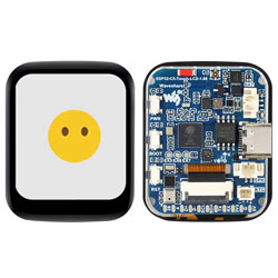
ESP32-C5-Touch-LCD-1.69 User Guide
Features
- Equipped with a high-performance RISC-V 32-bit processor and a low-power RISC-V 32-bit processor; the high-performance processor runs up to 240 MHz, and the low-power processor runs up to 48 MHz
- Integrated Wi-Fi 6, Bluetooth 5, and IEEE 802.15.4 (Zigbee 3.0 and Thread) wireless connectivity
- Onboard 320 KB ROM, 384 KB HP SRAM, 16 KB LP SRAM, and external 16 MB Flash
- Type-C port
- Onboard 1.69inch LCD screen with 240 × 280 resolution and 262K colors, capable of displaying colorful images clearly
- Built-in ST7789V2 driver IC, communicating via SPI interface, minimizing GPIO pin usage
- Onboard QMI8658 6-axis IMU (3-axis accelerometer, 3-axis gyroscope) for motion posture detection, step counting, etc.
- Onboard PCF85063 RTC chip for convenient RTC functionality implementation
- Onboard RST, BOOT, and a user-configurable side button for custom function development
- Onboard 3.7V MX1.25 lithium battery charge/discharge interface
- Onboard ES8311 audio codec chip, microphone, and speaker for voice applications such as XiaoZhi AI
- Exposed GPIO, I2C, USB, and UART pads for external devices and debugging, allowing flexible peripheral configuration
- Supports flexible clock and independent module power control for low-power operation in various scenarios
Onboard Resources
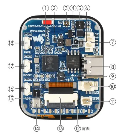
ESP32-C5HR8 Features a RISC-V 32-bit processor, integrates 384 KB HP SRAM and 320 KB ROM, supports 2.4 GHz/5 GHz dual-band Wi-Fi 6, Bluetooth 5 (LE), and IEEE 802.15.4 (Zigbee 3.0, Thread)
DC-DC Buck-Boost Converter Chip
IPEX 4 Antenna Connector
16MB Flash Memory
ETA6098 Battery Charging Management Chip
BQ27220 Fuel Gauge Chip Provides Battery capacity information
MX1.25 2P Lithium Battery Header MX1.25 2P connector for 3.7 V lithium battery, supports charging and discharging
Type-C Port for programming and serial logging
QMI8658 6-axis IMU, includes a 3-axis gyroscope and a 3-axis accelerometer
MX1.25 Speaker Header
SH1.0 RTC Battery Header For connecting a CR2032 Battery with an SH1.0 connector (1.0 mm pitch, forward type)
ES8311 (back side) Audio capture and codec chip
LCD Display Connector For connecting the LCD display
Microphone For audio signal capture
PCF85063 RTC Chip
RST Button Reset button; can also be used with the BOOT button to enter the download mode
BOOT Button Can be used as a custom button
PWR Button Press and hold for 3 seconds to power ON/OFF
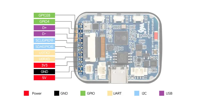
Pin Definitions
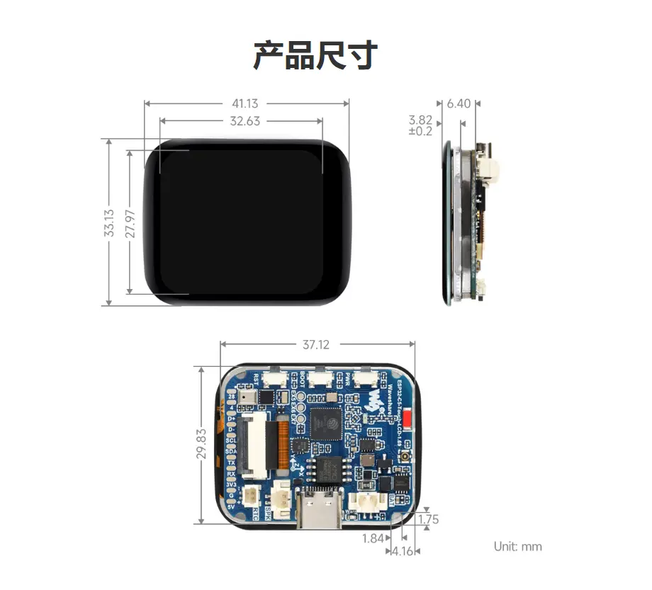
Dimensions
Working with Arduino
This chapter includes the following sections. Please read as needed:
Arduino Getting Started
New to Arduino ESP32 development and looking for a quick start? We have prepared a comprehensive Getting Started Tutorial for you.
- Section 0: Getting to Know ESP32
- Section 1: Installing and Configuring Arduino IDE
- Section 2: Arduino Basics
- Section 3: Digital Output/Input
- Section 4: Analog Input
- Section 5: Pulse Width Modulation (PWM)
- Section 6: Serial Communication (UART)
- Section 7: I2C Communication
- Section 8: SPI Communication
- Section 9: Wi-Fi Basics
- Section 10: Web Server
- Section 11: Bluetooth
- Section 12: LVGL GUI Development
- Section 13: Comprehensive Project
Note: This tutorial uses the ESP32-S3-Zero as a reference example, and all hardware code is based on its pinout. Before you start, we recommend checking the pinout of your development board to ensure the pin configuration is correct.
Setting Up the Development Environment
Install Arduino IDE
Please refer to the Install and Configure Arduino IDE Tutorial to install the Arduino IDE and add ESP32 board support.
Select Board and Port
After connecting the ESP32-C5-Touch-LCD-1.69 to your computer, select the corresponding serial port in the "Tools" menu.
Install Example Libraries
The Arduino examples are located in the example/arduino/examples directory. Before running an example, first extract example/arduino/ESP32_C5_Touch_LCD_1in69.zip, then copy the extracted library into the Arduino default libraries directory.
The Arduino libraries folder is typically located at:
C:/Users/<username>/Documents/Arduino/libraries
You can also check the "Sketchbook location" in Arduino IDE via "File > Preferences", and find the libraries folder under that path.
Example
| Example | Basic Description |
|---|---|
| 01_RGB_Test | Screen color cycling test |
| 02_Mic_Speaker_Test | Microphone and speaker test |
| 03_IMU_Test | IMU test |
| 04_Bat_Test | Battery detection test |
| 05_RTC_Test | RTC test |
| 06_LVGL_Demo_Test | LVGL example test |
01_RGB_Test
Hardware Connection
- Connect the development board to a computer using a USB cable.
Code Analysis
RGB color cycling test code
static const uint16_t Colors[] = {
    0xF800,  // Red
    0x07E0,  // Green
    0x001F,  // Blue
    0xFFFF,  // White
    0x0000,  // Black
};

static const char *ColorNames[] = {
    "R", "G", "B", "W", "BL",
};

void setup(void)
{
    Serial.begin(115200);
    delay(200);

    if (!bsp_display_init()) {
        Serial.println("bsp_display_init failed");
        while (true) {
            delay(1000);
        }
    }

    bsp_display_backlight_on();
    bsp_display_brightness_set(100);
}

void loop(void)
{
    bsp_display_fill(Colors[color_index]);
    Serial.printf("Show color: %s (%u)\n", ColorNames[color_index], color_index);

    color_index++;
    if (color_index >= (sizeof(Colors) / sizeof(Colors[0]))) {
        color_index = 0;
    }

    delay(2000);
}
Code Explanation
Colors[]/ColorNames[]: RGB565 color values and name arrays (red/green/blue/white/black) for cycling through full-screen fills.bsp_display_init(): Initializes the SPI bus and ST7789 LCD panel.bsp_display_backlight_on(): Turns on the LCD backlight.bsp_display_brightness_set(100): Sets backlight brightness to 100%.bsp_display_fill(Colors[color_index]): Fills the entire screen with the specified RGB565 color.Serial.printf(...): Outputs the current color name and index via serial for debugging.
Expected Behavior
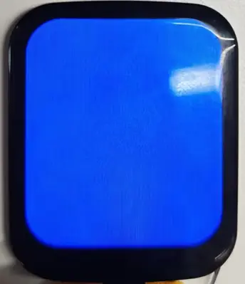
- The screen displays pure colors in sequence: red, green, blue, white, black, each for 2 seconds before switching.
- The serial port outputs the current color name and index every 2 seconds.
02_Mic_Speaker_Test
Hardware Connection
- Connect the development board to a computer using a USB cable.
Code Analysis
Microphone loopback playback code
constexpr size_t audio_frame_bytes = 1024;
constexpr uint8_t speaker_volume = 70;
constexpr uint8_t mic_gain_db = 18;

uint8_t audio_buffer[audio_frame_bytes];

void setup()
{
    Serial.begin(115200);

    if (!bsp_audio_init()) {
        Serial.println("bsp_audio_init failed");
        return;
    }

    bsp_audio_set_speaker_volume(speaker_volume);
    bsp_audio_set_mic_gain(mic_gain_db);

    Serial.println("microphone loopback to speaker");
}

void loop()
{
    size_t bytes_read = 0;
    size_t bytes_written = 0;

    if (!bsp_audio_read(audio_buffer, sizeof(audio_buffer), &bytes_read) || (bytes_read == 0)) {
        Serial.println("bsp_audio_read failed");
        delay(10);
        return;
    }

    if (!bsp_audio_write(audio_buffer, bytes_read, &bytes_written) || (bytes_written != bytes_read)) {
        Serial.println("bsp_audio_write failed");
        delay(10);
    }
}
Code Explanation
bsp_audio_init(): Initializes the I2S bus and ES8311 codec.bsp_audio_set_speaker_volume(70): Sets speaker volume to 70.bsp_audio_set_mic_gain(18): Sets microphone gain to 18dB.bsp_audio_read(audio_buffer, ...): Reads 1024 bytes of audio data from the microphone.bsp_audio_write(audio_buffer, ...): Writes the read audio data to the speaker, implementing real-time loopback.
Expected Behavior
- Serial output shows
microphone loopback to speaker. - Speaking into the microphone allows real-time playback from the speaker.
03_IMU_Test
Hardware Connection
- Connect the development board to a computer using a USB cable.
Code Analysis
QMI8658 initialization and data reading code
#define QMI8658_I2C_ADDRESS 0x6B

static QMI8658 imu(Wire);
static AccelData accel_data = { 0 };
static GyroData gyro_data = { 0 };

void setup(void)
{
    Serial.begin(115200);

    bsp_display_brightness_init();
    bsp_display_brightness_set(100);

    if (!bsp_i2c_init()) {
        Serial.println("I2C init failed");
        while (true) {
            delay(1000);
        }
    }

    imu.init(imu_calibration, QMI8658_I2C_ADDRESS);
    imu.setAccelRange(8);
    imu.setGyroRange(512);
    imu.setAccelODR(1000);
    imu.setGyroODR(1000);

    Serial.println("QMI8658 ready");
}

void loop(void)
{
    imu.update();
    imu.getAccel(&accel_data);
    imu.getGyro(&gyro_data);

    Serial.print("ACC[g] ");
    Serial.print(accel_data.accelX, 3);
    Serial.print(", ");
    Serial.print(accel_data.accelY, 3);
    Serial.print(", ");
    Serial.print(accel_data.accelZ, 3);
    Serial.print("  GYRO[dps] ");
    Serial.print(gyro_data.gyroX, 3);
    Serial.print(", ");
    Serial.print(gyro_data.gyroY, 3);
    Serial.print(", ");
    Serial.print(gyro_data.gyroZ, 3);
    Serial.print("  TEMP[C] ");
    Serial.println(imu.getTemp(), 2);

    delay(100);
}
Code Explanation
bsp_i2c_init(): Initializes the I2C bus (SDA=GPIO8, SCL=GPIO9, 400kHz).imu.init(imu_calibration, QMI8658_I2C_ADDRESS): Initializes the QMI8658 with I2C address 0x6B.imu.setAccelRange(8)/imu.setGyroRange(512): Sets accelerometer range to ±8g and gyroscope range to ±512dps.imu.setAccelODR(1000)/imu.setGyroODR(1000): Sets accelerometer and gyroscope output data rate to 1000Hz.imu.update(): Updates sensor data.imu.getAccel(&accel_data)/imu.getGyro(&gyro_data): Reads accelerometer and gyroscope data.imu.getTemp(): Reads temperature data.
Expected Behavior
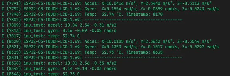
- After serial output
QMI8658 ready, it prints accelerometer (g), gyroscope (dps), and temperature (°C) data every 100ms. - When the development board is slightly tilted or rotated, the accelerometer and gyroscope data will change accordingly.
04_Bat_Test
Hardware Connection
- Connect the development board to a computer using a USB cable.
- Connect a Lithium battery to the development board.
Code Analysis
Battery information reading and display code
static const uint16_t battery_capacity_mah = 1500;

static const bsp_display_lvgl_partial_cfg_t battery_display_cfg = {
    .use_psram = false,
    .double_buffer = false,
    .buffer_height = 120,
};

static void bat_update_label(const bsp_bat_info_t *bat_info)
{
    const char *battery_state = "Idle";
    const char *battery_note = "";

    battery_state = (bat_info->ma > 0) ? "Charging" : ((bat_info->ma < 0) ? "Discharging" : "Idle");
    battery_note = (bat_info->ma == 0) ? "battery not connected or full" : "battery connected";

    lv_label_set_text_fmt(battery_label,
        "Battery Test\n"
        "State: %s\n"
        "Voltage: %u mV\n"
        "Current: %d mA\n"
        "SOC: %u %%\n"
        "Temp: %d C\n"
        "Capacity: %u mAh\n"
        "%s",
        battery_state,
        bat_info->mv,
        bat_info->ma,
        bat_info->soc,
        bat_info->tc,
        battery_capacity_mah,
        battery_note);
}

void setup(void)
{
    bsp_display_start_partial(&battery_display_cfg);
    bsp_display_brightness_set(100);
    bsp_bat_init(battery_capacity_mah);

    bsp_display_lock(0);
    battery_label = lv_label_create(lv_scr_act());
    lv_obj_align(battery_label, LV_ALIGN_TOP_LEFT, 10, 10);
    lv_label_set_text(battery_label, "Battery Test\nBattery status updating");
    bsp_display_unlock();
}

void loop(void)
{
    bsp_bat_info_t bat_info = {};

    if (!bsp_get_bat_info(&bat_info)) {
        Serial.println("battery info update failed");
        return;
    }

    if (bat_info_changed(&battery_last_info, &bat_info)) {
        if (bsp_display_lock(0)) {
            bat_update_label(&bat_info);
            battery_last_info = bat_info;
            bsp_display_unlock();
        }
    }

    delay(1000);
}
Code Explanation
bsp_display_start_partial(&battery_display_cfg): Starts LVGL in partial refresh mode to reduce framebuffer memory usage.bsp_bat_init(battery_capacity_mah): Initializes the BQ27220 fuel gauge with battery capacity set to 1500mAh.bsp_get_bat_info(&bat_info): Reads battery information (voltage/current/SOC/temperature, etc.).bsp_display_lock(0)/bsp_display_unlock(): Acquires/releases the LVGL mutex for thread safety.lv_label_set_text_fmt(battery_label, ...): Formats and updates the battery information label.bat_info_changed(...): Checks whether battery data has changed to avoid unnecessary refreshes.
Expected Behavior
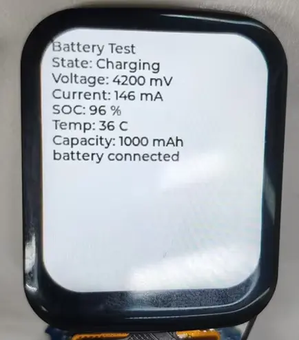
- The screen displays battery status information: State (Charging/Discharging/Idle), Voltage (mV), Current (mA), SOC (%), Temperature (°C), Capacity (mAh).
- Serial output also shows battery data.
- When a battery is connected and current is non-zero, the state shows Charging or Discharging; when no battery is connected or fully charged, it shows Idle.
05_RTC_Test
Hardware Connection
- Connect the development board to a computer using a USB cable.
Code Analysis
RTC initialization and time reading code
static PCF85063A rtc(Wire);
static void rtc_set_to_build_time(void)
{
struct tm now_tm = {};
const char *build_date = __DATE__;
const char *build_time = __TIME__;
now_tm.tm_year = ((build_date[7] - '0') * 1000 + (build_date[8] - '0') * 100 +
(build_date[9] - '0') * 10 + (build_date[10] - '0')) - 1900;
now_tm.tm_mon = month_from_build_date(build_date);
now_tm.tm_mday = (build_date[4] == ' ') ? (build_date[5] - '0')
: ((build_date[4] - '0') * 10 + (build_date[5] - '0'));
now_tm.tm_hour = (build_time[0] - '0') * 10 + (build_time[1] - '0');
now_tm.tm_min = (build_time[3] - '0') * 10 + (build_time[4] - '0');
now_tm.tm_sec = (build_time[6] - '0') * 10 + (build_time[7] - '0');
rtc.set(&now_tm);
}
void setup(void)
{
Serial.begin(115200);
bsp_display_brightness_init();
bsp_display_brightness_set(100);
bsp_i2c_init();
rtc.begin();
if (rtc.oscillator_stop()) {
Serial.println("RTC lost power, set to build time");
rtc_set_to_build_time();
} else {
Serial.println("RTC running");
}
}
void loop(void)
{
time_t current_time = rtc.time(NULL);
struct tm *now_tm = localtime(¤t_time);
Serial.printf("%04d-%02d-%02d %02d:%02d:%02d\r\n",
now_tm->tm_year + 1900,
now_tm->tm_mon + 1,
now_tm->tm_mday,
now_tm->tm_hour,
now_tm->tm_min,
now_tm->tm_sec);
delay(1000);
}
Code Explanation
bsp_i2c_init(): Initializes the I2C bus.rtc.begin(): Initializes the PCF85063A RTC chip.rtc.oscillator_stop(): Checks whether the RTC oscillator has stopped (power loss); returns true if time is lost.rtc_set_to_build_time(): Sets RTC time using the compile time (__DATE__/__TIME__).rtc.time(NULL): Reads the RTC timestamp.localtime(¤t_time): Converts timestamp to local time structure for formatted output.
Expected Behavior
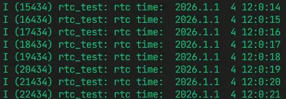
- Serial output shows
RTC runningorRTC lost power, set to build time. - Then outputs time in
YYYY-MM-DD HH:MM:SSformat every second.
06_LVGL_Demo_Test
Hardware Connection
- Connect the development board to a computer using a USB cable.
Code Analysis
LVGL Benchmark initialization code
static const bsp_display_lvgl_full_frame_cfg_t lgvl_config = {
    .use_psram = true,
    .double_buffer = true,
    .full_refresh = true,
};

void setup(void)
{
    Serial.begin(115200);
    bsp_display_start_full_frame(&lgvl_config);
    bsp_display_brightness_set(100);

    bsp_display_lock(0);
    lv_demo_benchmark_set_max_speed(true);
    lv_demo_benchmark();
    bsp_display_unlock();
}

void loop(void)
{
    delay(1000);
}
Code Explanation
bsp_display_start_full_frame(&lgvl_config): Starts LVGL in full-frame mode with PSRAM, double buffering, and full refresh enabled for best display performance.bsp_display_brightness_set(100): Sets backlight brightness to 100%.bsp_display_lock(0)/bsp_display_unlock(): Acquires/releases the LVGL mutex for thread-safe UI operations.lv_demo_benchmark_set_max_speed(true): Sets benchmark to maximum speed mode.lv_demo_benchmark(): Starts the LVGL benchmark performance test.
Expected Behavior
- The screen sequentially displays various LVGL benchmark test scenes (rectangle, shadow, text, image, animation, and other rendering performance tests).
- After the test completes, a summary of FPS scores is displayed.
Working with ESP-IDF
This chapter includes the following sections, please read as needed:
ESP-IDF Getting Started
New to ESP32 ESP-IDF development and looking to get started quickly? We have prepared a general Getting Started Tutorial for you.
- Section 1: Environment Setup
- Section 2: Running Examples
- Section 3: Creating a Project
- Section 4: Using Components
- Section 5: Debugging
- Section 6: FreeRTOS
- Section 7: Peripherals
- Section 8: Wi-Fi Programming
- Section 9: BLE Programming
Please Note: This tutorial uses the ESP32-S3-Zero as a teaching example, and all hardware code is based on its pinout. Before you start, it is recommended that you check the pinout of your development board to ensure the pin configuration is correct.
Setting Up the Development Environment
The ESP32-C5-Touch-LCD-1.69 example project requires ESP-IDF v5.3 or newer.
The following guide uses Windows as an example, demonstrating development using VS Code + the ESP-IDF extension. macOS and Linux users should refer to the official documentation.
The screenshots in this section use ESP-IDF V5.5.2 as an example. When installing, please select the ESP-IDF version that matches your board's example.
Install the ESP-IDF Development Environment
Download the installation manager from the ESP-IDF Installation Manager page. This is Espressif's latest cross-platform installer. The following steps demonstrate how to use its offline installation feature.
Click the Offline Installer tab on the page, then select Windows as the operating system and the ESP-IDF version you need (the version shown in the screenshot is for reference only — choose the version that fits your actual needs).
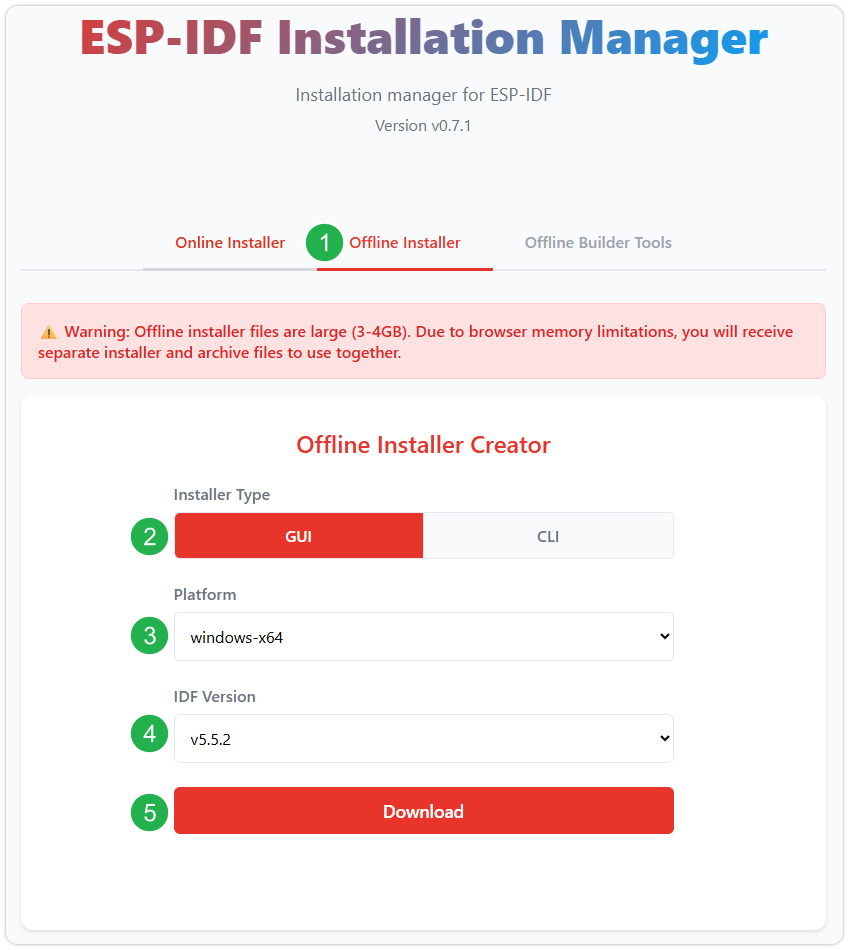
After confirming your selection, click the download button. The browser will automatically download two files: the ESP-IDF Offline Package (.zst) and the ESP-IDF Installer (.exe).
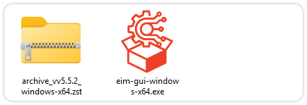
Please wait for both files to finish downloading.
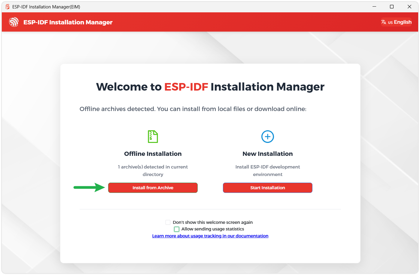
Once the download is complete, double-click to run the ESP-IDF Installer (eim-gui-windows-x64.exe).
The installer will automatically detect if the offline package exists in the same directory. Click Install from archive.
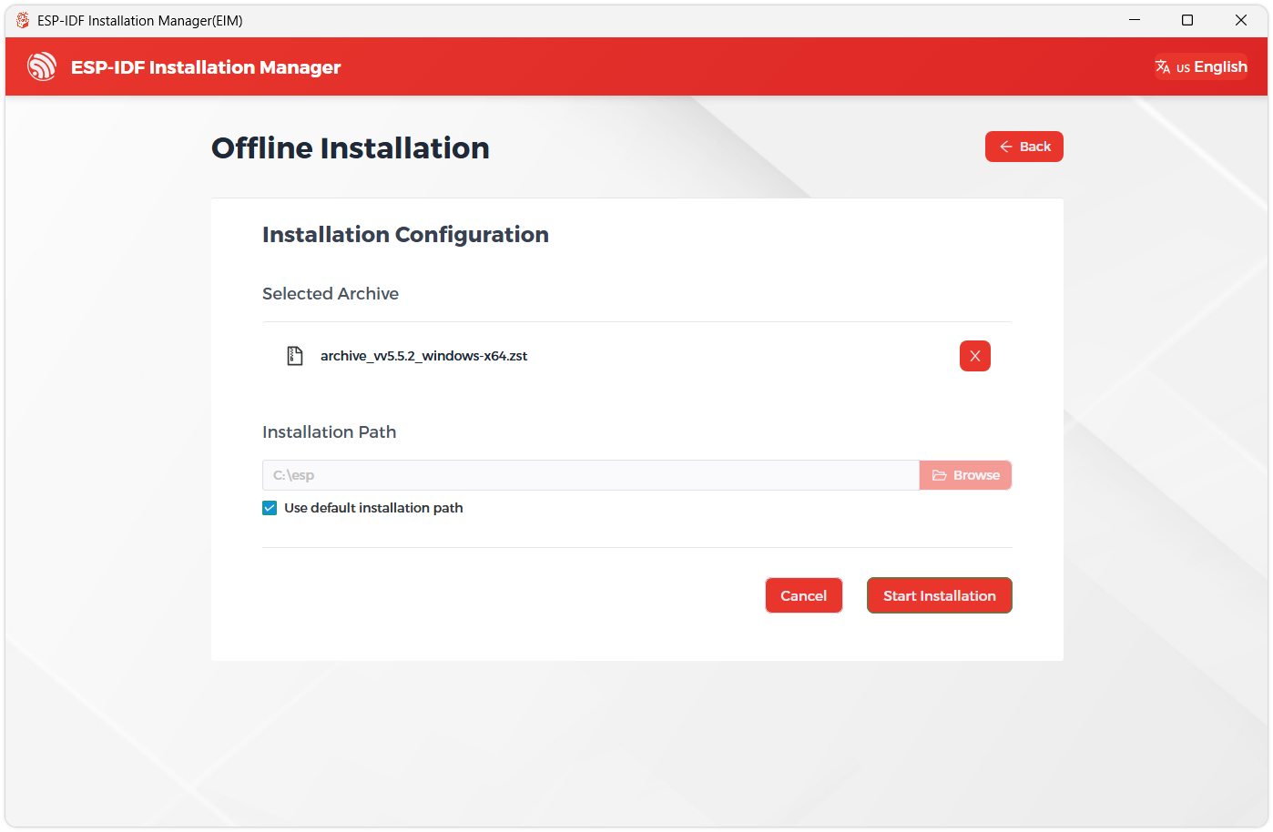
Next, select the installation path. We recommend using the default path. If you need to customize it, ensure the path does not contain Chinese characters or spaces. Click Start installation to proceed.
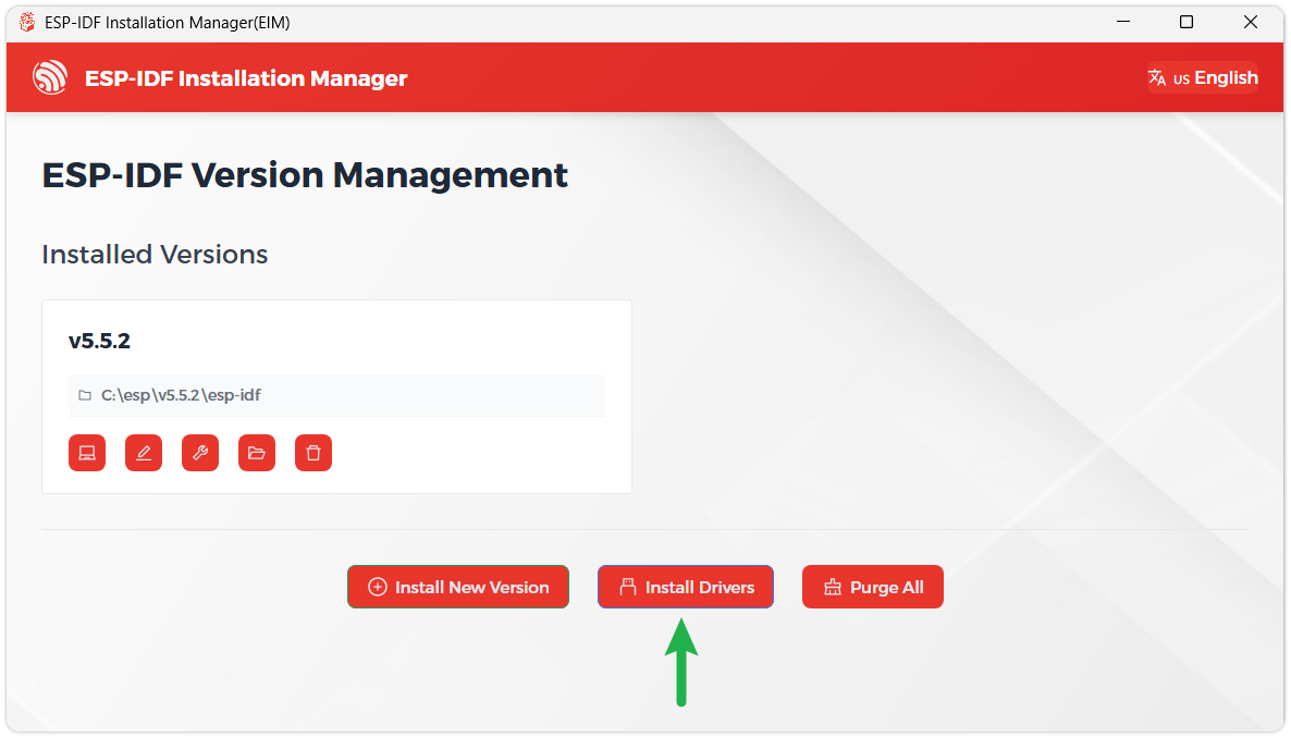
When you see the following screen, the ESP-IDF installation is successful.
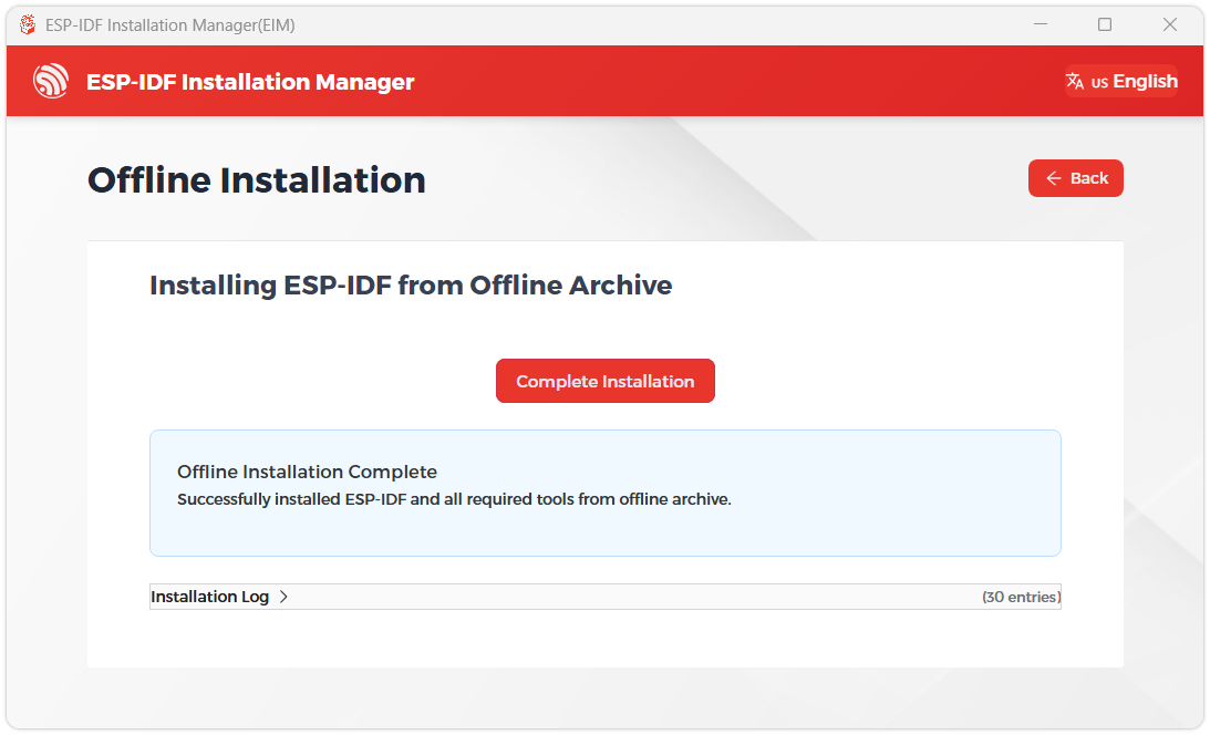
We recommend installing the drivers as well. Click Finish installation, then select Install driver.
Install Visual Studio Code and the ESP-IDF Extension
Download and install Visual Studio Code.
During installation, it is recommended to check Add "Open with Code" action to Windows Explorer file context menu to facilitate opening project folders quickly.
In VS Code, click the Extensions icon
 in the Activity Bar on the side (or use the shortcut Ctrl + Shift + X) to open the Extensions view.
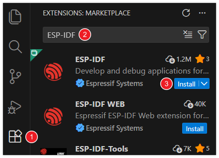
Enter ESP-IDF in the search box, locate the ESP-IDF extension, and click Install.
For ESP-IDF extension versions ≥ 2.0, the extension will automatically detect and recognize the ESP-IDF environment installed in the previous steps, requiring no manual configuration.
If installation fails or a reinstall is needed, you can try deleting the C:\Users\%Username%\esp and C:\Users\%Username%\.espressif folders and then retry.
Building and Flashing
Navigate to the ESP-IDF example project directory and run:
cd example/esp-idf
idf.py build flash monitor
If you need to specify a serial port, replace COMx with the actual port, for example COM5:
idf.py -p COMx build flash monitor
Example
ESP-IDF examples are located in the example/esp-idf/main/examples directory, and the project entry is example/esp-idf/main/main.c. At any time, keep only one example or application macro set to 1, and set all others to 0.
#define EXAMPLE_RGB_TEST            1
#define EXAMPLE_MIC_SPEAKER_TEST    0
#define EXAMPLE_IMU_TEST            0
#define EXAMPLE_BAT_TEST            0
#define EXAMPLE_RTC_TEST            0
#define EXAMPLE_LVGL_DEMO_TEST      0
#define EXAMPLE_Brookesia_TEST      0

#define APPS_WIFI_Connect           0
#define APPS_Clock                  0
#define APPS_Honeycomb_Demo         0
By default, the RGB color cycling test runs. To run another example, change the corresponding macro to 1 and set all others to 0.
| Example | Basic Description |
|---|---|
| 01_RGB_Test | Screen color cycling test |
| 02_Mic_Speaker_Test | Microphone and speaker test |
| 03_IMU_Test | IMU test |
| 04_Bat_Test | Battery detection test |
| 05_RTC_Test | RTC test |
| 06_LVGL_Demo_Test | LVGL example test |
| 07_Brookesia_Test | Brookesia example test |
| 08_WIFI_Connect | Wi-Fi provisioning application |
| 09_Clock_Display | Clock display application |
| 10_Honeycomb_Demo | Honeycomb icon interactive demonstration |
01_RGB_Test
Hardware Connection
- Connect the development board to a computer using a USB cable.
Code Analysis
RGB color cycling test code
void rgb_test_run(void)
{
    static const uint16_t colors[] = { RGB565_RED, RGB565_GREEN, RGB565_BLUE };
    static const char *color_names[] = { "red", "green", "blue" };
    bsp_display_cfg_t display_cfg = {0};
    esp_lcd_panel_handle_t panel = NULL;
    uint16_t *draw_buffer = NULL;
    size_t color_index = 0;

    ESP_ERROR_CHECK(bsp_display_new(&display_cfg, &panel, NULL));
    ESP_ERROR_CHECK(bsp_display_brightness_init());
    ESP_ERROR_CHECK(bsp_display_brightness_set(100));

    draw_buffer = heap_caps_malloc(BSP_LCD_H_RES * RGB_TEST_BLOCK_LINES * sizeof(uint16_t), MALLOC_CAP_DMA);

    while (true) {
        ESP_LOGI(TAG, "show color: %s", color_names[color_index]);
        rgb_test_draw_color(panel, draw_buffer, colors[color_index]);
        vTaskDelay(pdMS_TO_TICKS(RGB_TEST_DELAY_MS));

        color_index++;
        if (color_index >= (sizeof(colors) / sizeof(colors[0]))) {
            color_index = 0;
        }
    }
}
Code Explanation
bsp_display_new(&display_cfg, &panel, NULL): Initializes the LCD panel and returns a panel handle.bsp_display_brightness_init()/bsp_display_brightness_set(100): Initializes and sets backlight brightness to 100%.heap_caps_malloc(..., MALLOC_CAP_DMA): Allocates a DMA-compatible draw buffer for bulk pixel transfers.rgb_test_draw_color(panel, draw_buffer, colors[color_index]): Writes the specified color to the LCD in 20-line blocks, refreshing the entire screen block by block.vTaskDelay(pdMS_TO_TICKS(RGB_TEST_DELAY_MS)): Each color stays for 1 second.
Expected Behavior
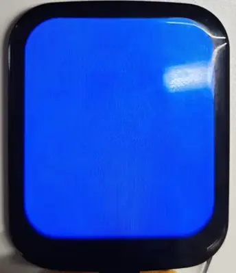
- The screen displays red, green, and blue in sequence, each for 1 second.
- The serial port outputs the current color name every second.
02_Mic_Speaker_Test
Hardware Connection
- Connect the development board to a computer using a USB cable.
Code Analysis
Microphone loopback playback code
void mic_speaker_test_run(void)
{
    uint8_t audio_buffer[MIC_SPEAKER_TEST_FRAME_BYTES];
    esp_codec_dev_handle_t speaker = NULL;
    esp_codec_dev_handle_t microphone = NULL;
    esp_codec_dev_sample_info_t codec_fs = {
        .sample_rate = BSP_AUDIO_OUTPUT_SAMPLE_RATE_HZ,
        .bits_per_sample = 16,
        .channel = 1,
    };

    ESP_ERROR_CHECK(bsp_audio_init(NULL));

    speaker = bsp_audio_codec_speaker_init();
    microphone = bsp_audio_codec_microphone_init();

    ESP_ERROR_CHECK(esp_codec_dev_open(speaker, &codec_fs));
    ESP_ERROR_CHECK(esp_codec_dev_set_out_vol(speaker, MIC_SPEAKER_TEST_VOLUME));
    ESP_ERROR_CHECK(esp_codec_dev_set_in_gain(microphone, MIC_SPEAKER_TEST_GAIN));

    ESP_LOGI(TAG, "microphone loopback to speaker");

    while (true) {
        ESP_ERROR_CHECK(esp_codec_dev_read(microphone, audio_buffer, sizeof(audio_buffer)));
        ESP_ERROR_CHECK(esp_codec_dev_write(speaker, audio_buffer, sizeof(audio_buffer)));
    }
}
Code Explanation
bsp_audio_init(NULL): Initializes the I2S bus and ES8311 codec.bsp_audio_codec_speaker_init()/bsp_audio_codec_microphone_init(): Initializes the speaker and microphone codec devices, respectively.esp_codec_dev_open(speaker, &codec_fs): Opens the speaker device in 16-bit mono format.esp_codec_dev_set_out_vol(speaker, 70): Sets speaker volume to 70.esp_codec_dev_set_in_gain(microphone, 18): Sets microphone gain to 18dB.esp_codec_dev_read(...)/esp_codec_dev_write(...): Reads 1024 bytes from the microphone and writes them to the speaker for real-time loopback.
Expected Behavior
- Serial output shows
microphone loopback to speaker. - Speaking into the microphone allows real-time playback from the speaker.
03_IMU_Test
Hardware Connection
- Connect the development board to a computer using a USB cable.
Code Analysis
QMI8658 data reading code
void imu_test_run(void)
{
    qmi8658_data_t data = {0};

    ESP_ERROR_CHECK(bsp_i2c_init());
    ESP_ERROR_CHECK(bsp_qmi8658_init());

    while (true) {
        ESP_ERROR_CHECK(bsp_qmi8658_get_data(&data));
        ESP_LOGI(TAG, "accel: %.2f %.2f %.2f m/s2", data.accelX, data.accelY, data.accelZ);
        ESP_LOGI(TAG, "gyro: %.2f %.2f %.2f rad/s", data.gyroX, data.gyroY, data.gyroZ);
        ESP_LOGI(TAG, "temp: %.2f C", data.temperature);
        vTaskDelay(pdMS_TO_TICKS(IMU_TEST_DELAY_MS));
    }
}
Code Explanation
bsp_i2c_init(): Initializes the I2C bus (SDA=GPIO8, SCL=GPIO9, 400kHz).bsp_qmi8658_init(): Initializes the QMI8658 6-axis sensor at I2C address 0x6B.bsp_qmi8658_get_data(&data): Reads accelerometer, gyroscope, and temperature data into theqmi8658_data_tstructure.ESP_LOGI(TAG, ...): Outputs accelerometer (m/s²), gyroscope (rad/s), and temperature (°C) via serial.vTaskDelay(pdMS_TO_TICKS(IMU_TEST_DELAY_MS)): Reads data at the interval defined by the macro.
Expected Behavior
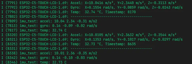
- The serial port outputs accelerometer, gyroscope, and temperature data every 500ms.
- Tilting or rotating the board causes the data to change accordingly.
04_Bat_Test
Hardware Connection
- Connect the development board to a computer using a USB cable.
- Connect a Lithium battery to the development board.
Code Analysis
Battery information reading and display code
void bat_test_run(uint16_t battery_capacity_mah)
{
    bsp_bat_info_t bat_info = {0};
    lv_display_t *display = NULL;
    lv_obj_t *label = NULL;

    display = bsp_display_start();
    ESP_ERROR_CHECK(bsp_display_brightness_set(100));
    ESP_ERROR_CHECK(bsp_bat_init(battery_capacity_mah));

    ESP_ERROR_CHECK(bsp_display_lock(0));
    label = lv_label_create(lv_screen_active());
    lv_obj_align(label, LV_ALIGN_TOP_LEFT, 10, 10);
    bsp_display_unlock();

    while (true) {
        ret = bsp_get_bat_info(&bat_info);
        if (ret != ESP_OK) {
            ESP_LOGW(TAG, "battery info update failed: %s", esp_err_to_name(ret));
            continue;
        }

        battery_state = (bat_info.ma > 0) ? "Charging" : ((bat_info.ma < 0) ? "Discharging" : "Idle");

        ESP_ERROR_CHECK(bsp_display_lock(0));
        lv_label_set_text_fmt(label,
            "Battery Test\n"
            "State: %s\n"
            "Voltage: %u mV\n"
            "Current: %d mA\n"
            "SOC: %u %%\n"
            "Temp: %u C\n"
            "Capacity: %u mAh\n"
            "%s",
            battery_state,
            bat_info.mv,
            bat_info.ma,
            bat_info.soc,
            bat_info.tc,
            battery_capacity_mah,
            battery_note);
        bsp_display_unlock();

        vTaskDelay(pdMS_TO_TICKS(BAT_TEST_DELAY_MS));
    }
}
Code Explanation
bsp_display_start(): Starts the LVGL display.bsp_bat_init(battery_capacity_mah): Initializes the BQ27220 fuel gauge with the battery capacity (passed as parameter, default 1000mAh).bsp_get_bat_info(&bat_info): Reads battery information (voltage/current/SOC/temperature/capacity, etc.).bsp_display_lock(0)/bsp_display_unlock(): Acquires/releases the LVGL mutex for thread-safe UI operations.lv_label_set_text_fmt(label, ...): Formats and updates the battery information label, including state, voltage, current, SOC, temperature, and capacity.
Expected Behavior
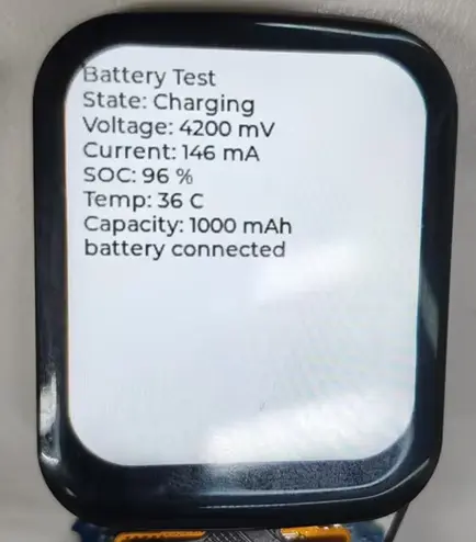
- The screen displays battery status information: State (Charging/Discharging/Idle), Voltage (mV), Current (mA), SOC (%), Temperature (°C), Capacity (mAh).
- Serial output also shows battery data.
- When a battery is connected and current is non-zero, the state shows Charging or Discharging; when no battery is connected or fully charged, it shows Idle.
05_RTC_Test
Hardware Connection
- Connect the development board to a computer using a USB cable.
Code Analysis
RTC initialization and time reading code
void rtc_test_run(void)
{
    char datetime_str[32];
    pcf85063a_datetime_t time = {
        .year = 2026,
        .month = 1,
        .day = 1,
        .dotw = 4,
        .hour = 12,
        .min = 0,
        .sec = 0,
    };

    ESP_ERROR_CHECK(bsp_rtc_init());
    ESP_ERROR_CHECK(bsp_set_rtc_time_date(time));

    while (true) {
        ESP_ERROR_CHECK(bsp_get_rtc_time_date(&time));
        ESP_ERROR_CHECK(bsp_datetime_to_str(datetime_str, sizeof(datetime_str), time));
        ESP_LOGI(TAG, "rtc time: %s", datetime_str);
        vTaskDelay(pdMS_TO_TICKS(RTC_TEST_DELAY_MS));
    }
}
Code Explanation
bsp_rtc_init(): Initializes the PCF85063A RTC chip.bsp_set_rtc_time_date(time): Sets the initial RTC time (example sets 2026-01-01 12:00:00).bsp_get_rtc_time_date(&time): Reads the current time from the RTC into thepcf85063a_datetime_tstructure.bsp_datetime_to_str(datetime_str, ...): Converts the time structure to a string for display.vTaskDelay(pdMS_TO_TICKS(RTC_TEST_DELAY_MS)): Reads time at the interval defined by the macro.
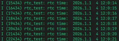
Expected Behavior
- The serial port outputs
rtc time: YYYY-MM-DD HH:MM:SSevery second.
06_LVGL_Demo_Test
Hardware Connection
- Connect the development board to a computer using a USB cable.
Code Analysis
LVGL Widgets Example Code
void lvgl_test_run(void)
{
    lv_display_t *display = NULL;

    display = bsp_display_start();
    ESP_ERROR_CHECK(display ? ESP_OK : ESP_FAIL);
    ESP_ERROR_CHECK(bsp_display_brightness_set(100));

    ESP_ERROR_CHECK(bsp_display_lock(0));

    /* Running Widgets Demo */
    lv_demo_widgets();
    bsp_display_unlock();

    ESP_LOGI(TAG, "LVGL demo started");

    while (true) {
        vTaskDelay(pdMS_TO_TICKS(LVGL_TEST_DELAY_MS));
    }
}
Code Explanation
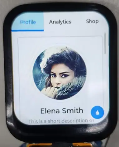
bsp_display_start(): Starts the LVGL display, initializing the LCD panel and LVGL core.bsp_display_brightness_set(100): Sets backlight brightness to 100%.bsp_display_lock(0)/bsp_display_unlock(): Acquires/releases the LVGL mutex for thread-safe UI operations.lv_demo_widgets(): Starts the LVGL Widgets example, showcasing common widgets such as buttons, sliders, switches, and charts.
Expected Behavior
- The screen displays the LVGL Widgets example interface with buttons, sliders, switches, charts, and other widgets.
- Touch interaction with the widgets is supported.
07_Brookesia_Test
Hardware Connection
- Connect the development board to a computer using a USB cable.
Code Analysis
Brookesia Phone initialization code
bool init_phone_system(void)
{
    ESP_Brookesia_PhoneStylesheet_t *stylesheet = nullptr;

    bsp_display_lock(0);

    phone = new (std::nothrow) ESP_Brookesia_Phone(display);
    stylesheet = new (std::nothrow) ESP_Brookesia_PhoneStylesheet_t(ESP_BROOKESIA_PHONE_DEFAULT_DARK_STYLESHEET());

    stylesheet->core.manager.flags.enable_app_save_snapshot = 0;
    stylesheet->core.manager.app.max_running_num = 1;
    stylesheet->home.flags.enable_recents_screen = 0;

    phone->addStylesheet(stylesheet);
    phone->activateStylesheet(stylesheet);
    phone->setTouchDevice(bsp_display_get_input_dev());

    phone->registerLvLockCallback(phone_lvgl_lock, 0);
    phone->registerLvUnlockCallback(phone_lvgl_unlock);

    phone->begin();
    phone->installApp(&minimal_app);

    bsp_display_unlock();
    return true;
}
Code Explanation
ESP_Brookesia_Phone(display): Creates a Brookesia Phone instance bound to the LVGL display.ESP_Brookesia_PhoneStylesheet_t(...): Uses the default dark theme stylesheet.phone->addStylesheet(stylesheet)/phone->activateStylesheet(stylesheet): Adds and activates the stylesheet.phone->setTouchDevice(bsp_display_get_input_dev()): Sets the touch input device.phone->registerLvLockCallback(...)/phone->registerLvUnlockCallback(...): Registers LVGL lock callbacks for thread safety.phone->begin(): Starts the Phone UI framework.phone->installApp(&minimal_app): Installs a minimal example app (displays "Hello Brookesia" text).
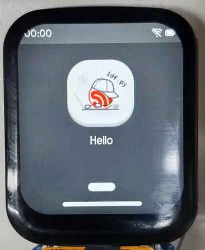
Expected Behavior
- The screen shows the Brookesia Phone interface with a status bar and app launcher.
- Tapping the app icon opens the "Hello Brookesia Minimal App" page.
08_WIFI_Connect
Hardware Connection
- Connect the development board to a computer using a USB cable.
Code Analysis
Wi-Fi AP and Captive Portal code
void wifi_connect_test_run(void)
{
    lv_display_t *display = NULL;

    wifi_connect_init_stack();
    wifi_connect_start_network();

    ESP_ERROR_CHECK(bsp_display_set_partial_mode(true, 40));

    display = bsp_display_start();
    ESP_ERROR_CHECK(bsp_display_brightness_set(100));
    ESP_ERROR_CHECK(bsp_display_lock(0));
    wifi_connect_create_screen();
    bsp_display_unlock();

    while (true) {
        vTaskDelay(pdMS_TO_TICKS(WIFI_CONNECT_IDLE_MS));
    }
}
Code Explanation
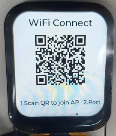
wifi_connect_init_stack(): Initializes NVS, network interface, and the default event loop.wifi_connect_start_network(): Creates an AP (SSID based on MAC address), starts HTTP and DNS servers for Captive Portal.bsp_display_set_partial_mode(true, 40): Sets LVGL to partial refresh mode to reduce memory usage.wifi_connect_create_screen(): Creates a provisioning screen with a QR code and status bar; the QR code contains the AP's SSID and password.- After the user's phone connects to the AP, the provisioning page automatically appears; after entering home Wi-Fi credentials, the device connects automatically.
Expected Behavior
- The screen displays a QR code and AP information; scanning the QR code and connecting to the AP automatically opens the provisioning page.
- Entering the home Wi-Fi SSID and password on the provisioning page allows the device to connect to Wi-Fi and display connection status and IP address on the screen.
09_Clock_Display
Hardware Connection
- Connect the development board to a computer using a USB cable.
Code Analysis
Clock application initialization code
void clock_test_run(void)
{
    lv_display_t *display = NULL;

    ESP_ERROR_CHECK(bsp_i2c_init());
    ESP_ERROR_CHECK(bsp_rtc_init());
    ESP_ERROR_CHECK(bsp_display_set_partial_mode(true, 40));

    display = bsp_display_start();
    ESP_ERROR_CHECK(bsp_display_brightness_set(100));
    ESP_ERROR_CHECK(bsp_display_lock(0));
    clock_app_create_screen();
    bsp_display_unlock();

    while (true) {
        vTaskDelay(pdMS_TO_TICKS(CLOCK_APP_IDLE_MS));
    }
}
Code Explanation
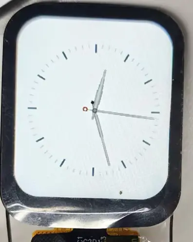
bsp_i2c_init()/bsp_rtc_init(): Initializes the I2C bus and the PCF85063A RTC, providing the time source for the clock.bsp_display_set_partial_mode(true, 40): Sets LVGL to partial refresh mode to reduce memory usage.bsp_display_start(): Starts the LVGL display.bsp_display_brightness_set(100): Sets backlight brightness to 100%.bsp_display_lock(0)/bsp_display_unlock(): Acquires/releases the LVGL mutex for thread-safe UI operations.clock_app_create_screen(): Creates the clock interface, loads the Classic watch face, and starts a timer to refresh the hands.vTaskDelay(pdMS_TO_TICKS(CLOCK_APP_IDLE_MS)): Idles at the interval defined by the macro.
Expected Behavior
- The screen displays an analog clock face with hour, minute, and second hands moving in real time according to the RTC.
10_Honeycomb_Demo
Hardware Connection
- Connect the development board to a computer using a USB cable.
Code Analysis
Honeycomb icon layout code
void honeycomb_demo_run(void)
{
    lv_display_t *display = NULL;

    display = bsp_display_start();
    ESP_ERROR_CHECK(bsp_display_brightness_set(100));
    ESP_ERROR_CHECK(bsp_display_lock(0));
    honeycomb_demo_create_screen();
    bsp_display_unlock();

    while (true) {
        vTaskDelay(pdMS_TO_TICKS(1000));
    }
}

static void honeycomb_demo_drag_event_cb(lv_event_t *event)
{
    lv_indev_t *indev = lv_indev_active();
    lv_point_t vector = {0};

    lv_indev_get_vect(indev, &vector);
    honeycomb_offset.x += vector.x;
    honeycomb_offset.y += vector.y;
    honeycomb_demo_refresh_layout();
}
Code Explanation
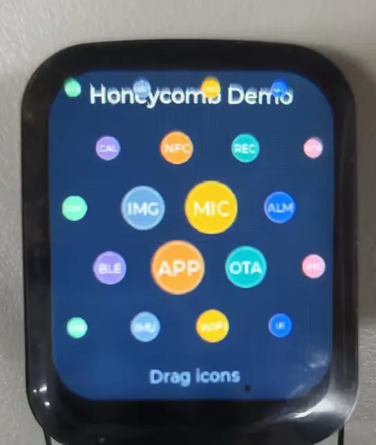
bsp_display_start(): Starts the LVGL display.honeycomb_demo_create_screen(): Creates a honeycomb layout with 25 circular icons arranged in a 5-column honeycomb grid.honeycomb_demo_drag_event_cb(...): Touch-drag callback that updates icon positions based on finger sliding offset.honeycomb_demo_refresh_layout(): Refreshes the icon layout, scaling each icon according to its distance from the screen center (closer = larger).honeycomb_demo_calculate_scale(distance): Calculates the icon scale using a quadratic decay function to achieve a fisheye magnifying effect.
Expected Behavior
- The screen displays colorful circular icons in a honeycomb arrangement, with the center icon enlarged and edge icons shrunk.
- Dragging with a finger pans the icon array; icons scale dynamically with position, creating a fisheye interaction effect.
XiaoZhi AI Application Tutorial
XiaozhiAI (XiaoZhi AI) is an open-source AI voice chatbot project based on the ESP32 development board, aiming to bring the general intelligence of large language models (LLMs) to edge devices. It provides a software-hardware integrated solution supporting full-duplex voice conversations and IoT device control, dedicated to assisting developers in building highly customized physical AI agents quickly and at low cost.
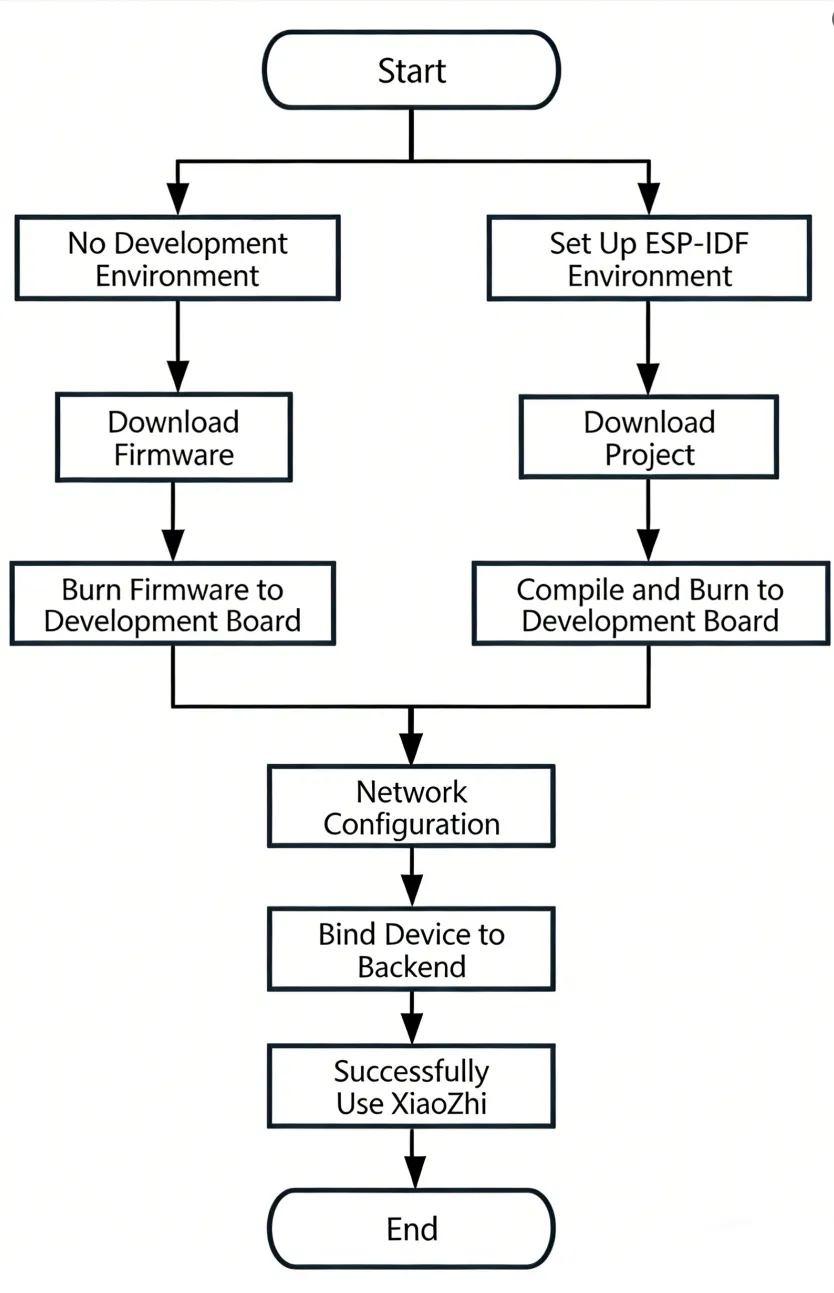
This article demonstrates how to flash firmware for Waveshare ESP32 development boards that support XiaoZhi AI, covering two methods: flashing without a development environment (directly flashing precompiled firmware) and flashing with a development environment (compiling from source and flashing).
0. Firmware Flashing Process Reference
This section uses the ESP32-S3-Touch-AMOLED-1.8 development board as an example. The steps are similar for other development boards.
Please first confirm that your hardware is listed in the XiaoZhi AI Supported Products List.
1. Flashing Without a Development Environment
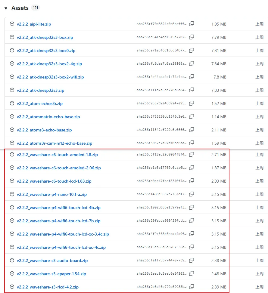
1.1 Download Firmware from XiaoZhi Official GitHub
Visit the XiaoZhi GitHub to download the firmware file for your device. Click Assets to expand the full file list:
Refer to the Flash Firmware Flashing and Erasing Tutorial to complete the firmware flashing.
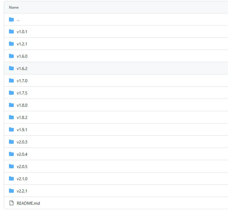
1.2 Download Firmware from Waveshare GitHub
This repository aggregates firmware for Waveshare ESP32 development boards that support XiaoZhi AI. All firmware has been tested and verified on the corresponding boards, making it convenient for users to find and download. Firmware versions may be updated slightly later than the official XiaoZhi repository.
Visit the Waveshare GitHub repository and download the appropriate firmware version for your needs:
Refer to the Flash Firmware Flashing and Erasing Tutorial to complete the firmware flashing.
2. Flashing with ESP-IDF Environment
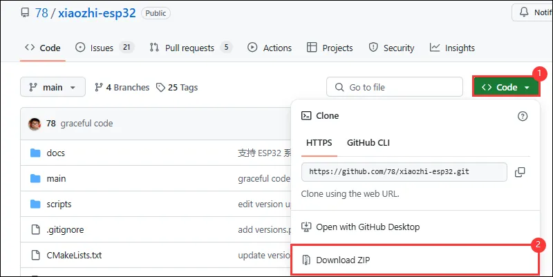
2.1 Download the Project from XiaoZhi GitHub
Visit the XiaoZhi AI Chatbot repository to download the complete project code:
2.2 Environment Setup
Refer to the ESP-IDF Environment Setup Tutorial to configure the development environment.
2.3 Configuration and Compilation
Click
 to select the target device. Choose the chip model corresponding to your development board (e.g.,
 esp32s3):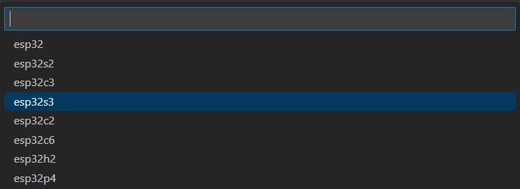 TIP
TIPWhen setting the target device, ESP-IDF will automatically configure the corresponding toolchain and libraries. This process may take some time, please be patient. For more details, please refer to the Official Documentation.
Click
 to open the ESP-IDF terminal, then execute the command
 idf.py menuconfigto enter the configuration interface. Select Xiaozhi Assistant: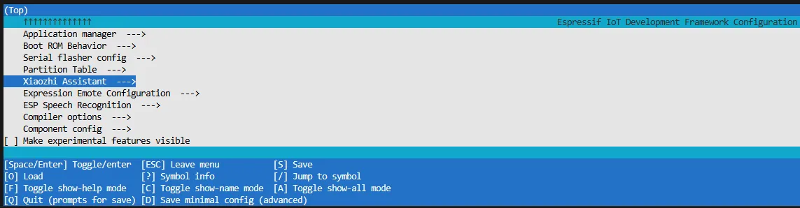
Select Board Type to choose the development board type:
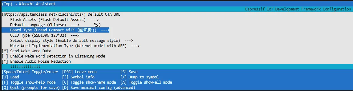
Choose the product model corresponding to your development board:
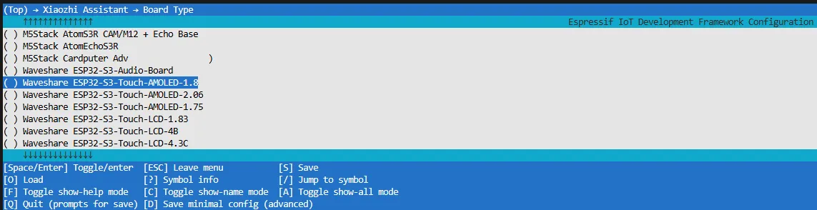
Press the S key to save the configuration and exit. Then click the
 to automatically complete compilation, flashing, and serial monitoring.
2.4 Start Network Provisioning
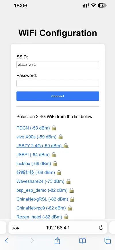
Connect your phone or computer to the device's Wi-Fi hotspot: Xiaozhi-xxxxxx. After successful connection, the configuration page should automatically pop up. If not, manually open a browser and visit
http://192.168.4.1.On the network configuration page, select the Wi-Fi name you want to connect to (only 2.4G band is supported; to connect to an iPhone hotspot, enable Max Compatibility in your phone's system settings). The SSID will be auto-filled. Enter the password and click Connect to start connecting:
2.5 Add a New Device to the Management Console
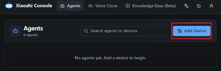
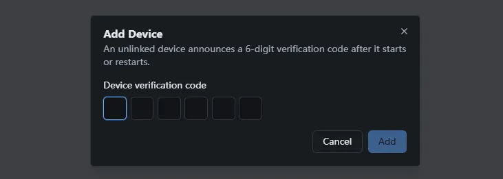
Ensure the device has successfully connected to the Internet. The device will then broadcast a 6-digit device verification code (you can wake the device again to replay the code).
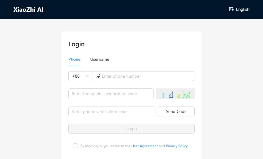
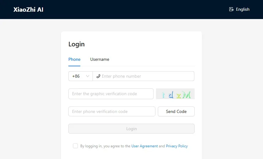
Visit the XiaoZhi AI Console. If you haven't registered, complete the registration and log in:
Enter the 6-digit verification code. The device will automatically activate and appear on the Device Management page, ready for normal use.
Say the wake word "Hello XiaoZhi" to wake the device and start voice conversations.
ESP32-S3-Touch-AMOLED-1.8 Button Instructions:
- BOOT button: Press to wake XiaoZhi
- PWR button: Short press to power on; long press for more than 6 seconds to power off
3. XiaoZhi Resources
Resources
Hardware Resources
Example
Firmware
Technical Manuals
- ESP32-C5 Technical Documentation
- ST7262 Datasheet
- ES8311 Datasheet
- PCF85063A Datasheet
- QMI8658 Datasheet
Software
Other Resource Links
Support
Monday-Friday (9:30-6:30) Saturday (9:30-5:30)
Email: services01@spotpear.com
[Tutorial Navigation]
- Features
- Onboard Resources
- Pin Definitions
- Dimensions
- Working with Arduino
- Arduino Getting Started
- Setting Up the Development Environment
- Example
- Working with ESP-IDF
- ESP-IDF Getting Started
- Setting Up the Development Environment
- Install the ESP-IDF Development Environment
- Install Visual Studio Code and the ESP-IDF Extension
- Building and Flashing
- Example
- XiaoZhi AI Application Tutorial
- 0. Firmware Flashing Process Reference
- 1. Flashing Without a Development Environment
- 2. Flashing with ESP-IDF Environment
- 2.1 Download the Project from XiaoZhi GitHub
- 2.2 Environment Setup
- 2.3 Configuration and Compilation
- 2.4 Start Network Provisioning
- 2.5 Add a New Device to the Management Console
- 3. XiaoZhi Resources
- Resources
- Support