


- sales/support
Google Chat:---
- sales
+86-0755-88291180
- sales01
sales@spotpear.com
- sales02
dragon_manager@163.com
- support
tech-support@spotpear.com
- CEO-Complaints
zhoujie@spotpear.com
- Only Tech-Support
WhatsApp:13246739196
- Purchase/Shipping/Refund
WhatsApp:13424403025
Raspberry Pi Pico-LCD-2 User Guide
Overview
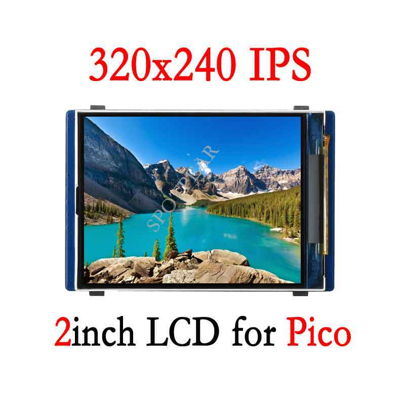
This 2inch LCD display module is designed for Raspberry Pi Pico, embedded ST7789VW driver, 65K RGB colors, 320 x 240 Pixels. SPI interface.
Features
- 320 × 240 resolution, IPS screen, 65K RGB colors, clear and colorful displaying effect.
- SPI interface requires minimal IO pins.
- 4 x user buttons for easy interaction.
Specifications
| Parameter name | Parameters |
| Power Supply | 2.6V ~ 5.5V |
| Working Current | 40mA |
| Screen Type | IPS |
| Control Chip | ST7789V |
| Communication Interface | 4-wire SPI |
| Resolution | 240 (V) RGB x 320 (H) Pixels |
| Pixel Size | 0.0975 (H) x 0.0975 (V)mm |
| Display Size | 30.6 (H) x 40.8 (V)mm |
| Product Size | 35 (H) x 52.00 (V)mm |
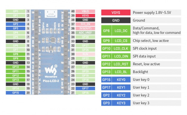
Pinout
LCD & Controller
The built-in controller used in this LCD is ST7789VW, which is an LCD controller with 240 x RGB x 320 pixels, while the pixels of this LCD itself are 240 (H) RGB x 320 (V), and the internal RAMYIJ of the LCD has been fully used.
The LCD supports 12-bit, 16-bit, and 18-bit input color formats per pixel, namely RGB444, RGB565, and RGB666 three color formats, this demo uses RGB565 color format, which is also a commonly used RGB format.
The LCD uses a four-wire SPI communication interface, which can greatly save the GPIO port, and the communication speed will be faster.
Working Protocol
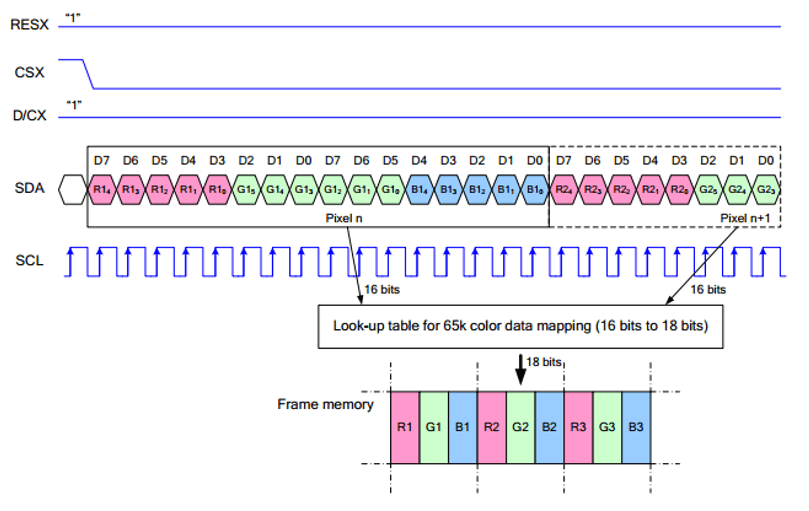
Note: Different from the traditional SPI protocol, the data line from the slave to the master is hidden since the device only has a display requirement.
RESX is the reset pin, it should be low when powering the module and be higher at other times;
CSX is a slave chip select, when CS is low, the chip is enabled.
D/CX is data/command control pin, when DC = 0, write command, when DC = 1, write data
SDA is the data pin for transmitting RGB data, it works as the MOSI pin of the SPI interface;
SCL works the SCLK pins of the SPI interface.
SPI communication has data transfer timing, which is combined by CPHA and CPOL.
CPOL determines the level of the serial synchronous clock at an idle state. When CPOL = 0, the level is Low. However, CPOL has little effect on the transmission.
CPHA determines whether data is collected at the first clock edge or at the second clock edge of the serial synchronous clock; when CPHL = 0, data is collected at the first clock edge.
As can be seen from the figure, when the first falling edge of SCLK starts to transmit data, 8bit data is transmitted in one clock cycle. When using SPI0, it is transmitted by bits, that is, high bit first, low bit last.
Pico Quick Start
Download Firmware
- MicroPython Firmware Download

- C_Blink Firmware Download

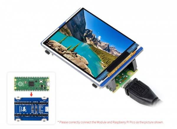
Hardware connection
Please take care of the direction when you connect Pico, an USB port is printed to indicate . You can also check the pin of Pico and the LCD board when connecting.
You can connect the display according to the table.
| LCD | Pico | Description |
| VCC | VSYS | Power Input |
| GND | GND | Ground |
| DIN | GP11 | MOSI pin of SPI, data transmitted from Master t Slave |
| CLK | GP10 | SCK pin of SPI, clock pin |
| CS | GP9 | Chip selection of SPI, low active |
| DC | GP8 | Data/Command control pin (High for data; Low for command) |
| RST | GP12 | Reset pin, low active |
| BL | GP13 | Backlight control |
| KEY0 | GP15 | User button KEY0 |
| KEY1 | GP17 | User button KEY1 |
| KEY2 | GP2 | User button KEY2 |
| KEY3 | GP3 | User button KEY3 |
Connection
Setup environment
Please refer to Raspberry Pi's guide: https://www.raspberrypi.org/documentation/pico/getting-started/
Download Demo codes
Open terminal and run the following command:
sudo apt-get install p7zip-full
cd ~
sudo wget  https://www.waveshare.com/w/upload/2/28/Pico_code.7z
7z x Pico_code.7z -o./Pico_code
cd ~/Pico_code
cd c/build/
Run the Demo codes
This guides is based on Raspberry Pi.
C Examples
Open a terminal and enter the directory of C codes:
cd ~/Pico_LCD_code/c/
Create a build folder and add SDK:
For example, if the path of SDK is ../../pico-sdk
Then you should create build and add the path like these:
mkdir build
cd build
export PICO_SDK_PATH=../../pico-sdk
Run cmake.. command to to generate Makefile file
cmake ..
Run make command to build.
make -j9
Open main.c under the c folder, you can change the routine you need. This routine can drive the display of our company's Pico series and the source code will be updated all the time. Please select the corresponding LCD or OLED test function and comment out the irrelevant functions.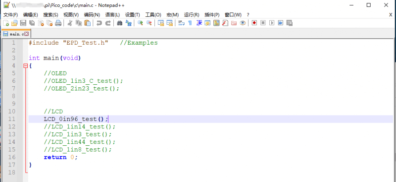
Run make command to build.
make -j9
After the compilation is complete, the uf2 file will be generated. Press and hold the button on the Pico board, connect the pico to the USB port of the Raspberry Pi through the Micro USB cable, and release the button. After connecting, the Raspberry Pi will automatically recognize a removable disk (RPI-RP2), and copy the main.uf2 file in the build folder to the recognized removable disk (RPI-RP2).
cp main.uf2 /media/pi/RPI-RP2/
Python codes
Use in Windows
- 1. Press and hold the BOOTSET button on the Pico board, connect the pico to the USB port of the computer through the Micro USB cable, and release the button after the computer recognizes a removable hard disk (RPI-RP2).
- 2. Copy the rp2-pico-20210418-v1.15.uf2 file in the python directory to the recognized removable disk (RPI-RP2).
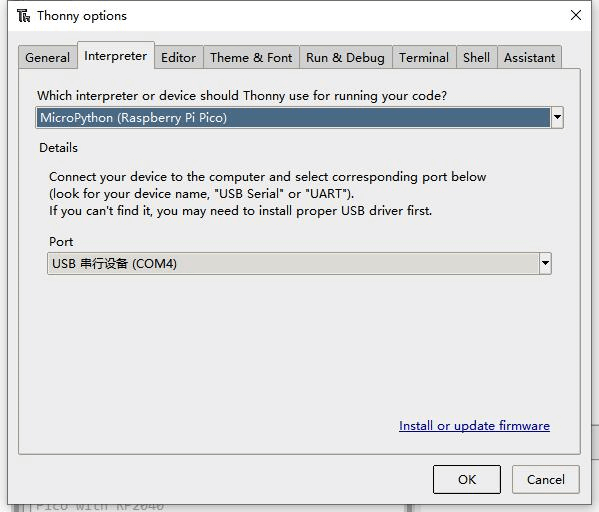
- 3. Open Thonny IDE (Note: Use the latest version of Thonny, otherwise there is no Pico support package, the latest version under Windows is v3.3.3).
- 4. Click Tools->Settings->Interpreter, select Pico and the corresponding port as shown in the figure.
- 5. File -> Open -> the corresponding .py file, click to run, as shown in the following figure:
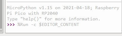
This demo provides a simple program...
Run in Raspberry Pi
- Hold the BOOTSET key of the Pico board, then connect the Pico to Raspberry Pi by USB cable, then release the key.
- Once the removable disk (RPI-RPI2) is recognized, copy the rp2-pico-20210418-v1.15.uf2 file to pico.
- Open the Thonny IDE in Raspberry Pi, and update it if it doesn't support Pico.
- Configure the port by choosing MicroPython(Raspberry Pi and ttyACM0 port) in Tools -> Options... -> Interpreter.
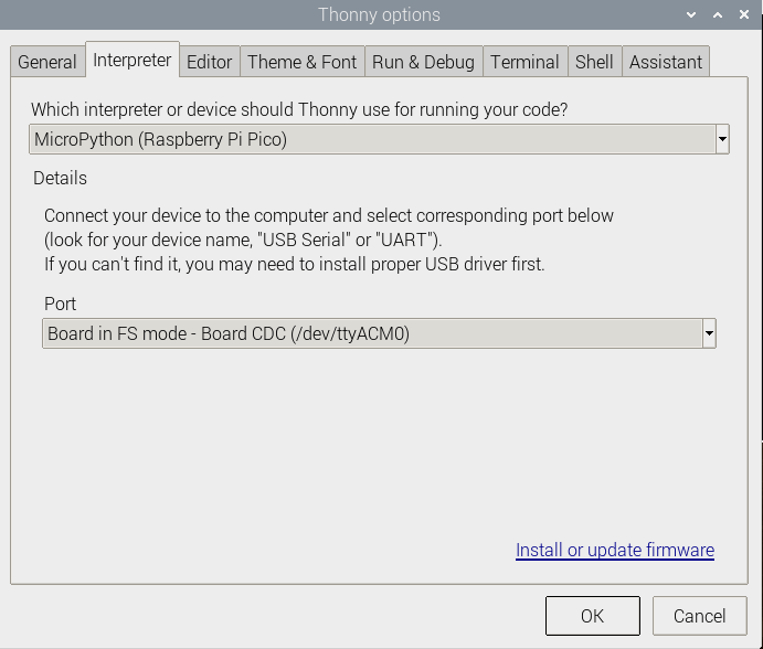
If your Thonny doesn't support Pico, you can update it with the following command:
sudo apt upgrade thonny
- Choose File->Open...->python/ and select the corresponding .py file to run the codes.
Codes Analysis
C
Bottom hardware interface
We package the hardware layer for easily porting to the different hardware platforms.
DEV_Config.c(.h) in the directory:...\c\lib\Config
- Data type:
#define UBYTE   uint8_t
#define UWORD   uint16_t
#define UDOUBLE uint32_t
- Module initialize and exit:
void DEV_Module_Init(void);
void DEV_Module_Exit(void);
Note:
1.The functions above are used to initialize the display or exit handle.
- GPIO write/read:
void 	DEV_Digital_Write(UWORD Pin, UBYTE Value);
UBYTE 	DEV_Digital_Read(UWORD Pin);
- SPI transmit data
void DEV_SPI_WriteByte(UBYTE Value);
Application functions
We provide basic GUI functions for testing, like draw point, line, string, and so on. The GUI function can be found in directory:..\c\lib\GUI\GUI_Paint.c(.h).
The fonts used can be found in the directory: RaspberryPi\c\lib\Fonts.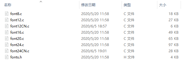
- Create a new image, you can set the image name, width, height, rotate angle, and color.
void Paint_NewImage(UWORD *image, UWORD Width, UWORD Height, UWORD Rotate, UWORD Color, UWORD Depth)
Parameter:
 	image: Name of the image buffer, this is a pointer;
 	Width: Width of the image;
 	Height: Height of the image;
 	Rotate: Rotate the angle of the Image;
 	Color: The initial color of the image;
 	Depth: Depth of the color
- Select image buffer: You can create multiple image buffers at the same time and select the certain one and draw by this function.
void Paint_SelectImage(UBYTE *image)
Parameter:
 	image: The name of the image buffer, this is a pointer;
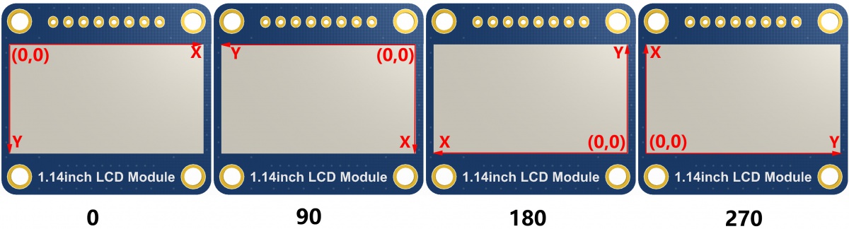
- Rotate image: You need to set the rotation angle of the image, this function should be used after Paint_SelectImage(). The angle can be 0, 90, 180, or 270.
void Paint_SetRotate(UWORD Rotate)
Parameter:
 	Rotate: Rotate angle of the image, the parameter can be ROTATE_0, ROTATE_90, ROTATE_180, ROTATE_270.
- 【Note】After rotating, the place of the first pixel is different as below:
- Image mirror: This function is used to set the image mirror.
void Paint_SetMirroring(UBYTE mirror)
Parameter:
 	mirror: Mirror type if the image, the parameter can be MIRROR_NONE、MIRROR_HORIZONTAL、MIRROR_VERTICAL、MIRROR_ORIGIN.
- Set the position and color of pixels: This is the basic function of GUI, it is used to set the position and color of a pixel in the buffer.
void Paint_SetPixel(UWORD Xpoint, UWORD Ypoint, UWORD Color)
Parameter:
 	Xpoint: The X-axis position of the point in the image buffer
 	Ypoint: The Y-axis position of the point in the image buffer
 	Color: The color of the point
- Color of the image: To set the color of the image, this function always be used to clear the display.
void Paint_Clear(UWORD Color)
Parameter:
 	Color: The color of the image
- Color of the windows: This function is used to set the color of windows, it is always used for updating partial areas like displaying a clock.
void Paint_ClearWindows(UWORD Xstart, UWORD Ystart, UWORD Xend, UWORD Yend, UWORD Color)
Parameter:
 	Xstart: X-axis position of the start point.
 	Ystart: Y-axis position of the start point.
 	Xend: X-axis position of the endpoint.
 	Yend: Y-axis position of the endpoint
 	Color: Color of the windows.
- Draw point: Draw a point at the position (Xpoint, Ypoint) of the image buffer, you can configure the color, size, and style.
void Paint_DrawPoint(UWORD Xpoint, UWORD Ypoint, UWORD Color, DOT_PIXEL Dot_Pixel, DOT_STYLE Dot_Style)
Parameter:
 	Xpoint: X-axis position of the point.
 	Ypoint: Y-axis position of the point
 	Color: Color of the point
 	Dot_Pixel: Size of the point, 8 sizes are available.
 	 	 typedef enum {
 	 	 	 DOT_PIXEL_1X1  = 1,	// 1 x 1
 	 	 	 DOT_PIXEL_2X2  , 		// 2 X 2
 	 	 	 DOT_PIXEL_3X3  , 	 	// 3 X 3
 	 	 	 DOT_PIXEL_4X4  , 	 	// 4 X 4
 	 	 	 DOT_PIXEL_5X5  , 		// 5 X 5
 	 	 	 DOT_PIXEL_6X6  , 		// 6 X 6
 	 	 	 DOT_PIXEL_7X7  , 		// 7 X 7
 	 	 	 DOT_PIXEL_8X8  , 		// 8 X 8
 	 	} DOT_PIXEL;
 	Dot_Style: Style of the point, it defines the extended mode of the point.
 	 	typedef enum {
 	 	   DOT_FILL_AROUND  = 1,
 	 	   DOT_FILL_RIGHTUP,
 	 	} DOT_STYLE;
- Draw the line: Draw a line from (Xstart, Ystart) to (Xend, Yend) in the image buffer, you can configure the color, width, and style.
void Paint_DrawLine(UWORD Xstart, UWORD Ystart, UWORD Xend, UWORD Yend, UWORD Color, LINE_STYLE Line_Style , LINE_STYLE Line_Style)
Parameter:
 	Xstart: Xstart of the line
 	Ystart: Ystart of the line
 	Xend: Xend of the line
 	Yend: Yend of the line
 	Color: Color of the line
 	Line_width: Width of the line, 8 sizes are available.
 	 	typedef enum {
 	 	 	 DOT_PIXEL_1X1  = 1,	// 1 x 1
 	 	 	 DOT_PIXEL_2X2  , 		// 2 X 2
 	 	 	 DOT_PIXEL_3X3  ,		// 3 X 3
 	 	 	 DOT_PIXEL_4X4  ,		// 4 X 4
 	 	 	 DOT_PIXEL_5X5  , 		// 5 X 5
 	 	 	 DOT_PIXEL_6X6  , 		// 6 X 6
 	 	 	 DOT_PIXEL_7X7  , 		// 7 X 7
 	 	 	 DOT_PIXEL_8X8  , 		// 8 X 8
 	 	} DOT_PIXEL;
 	 Line_Style: Style of the line, Solid or Dotted.
 	 	typedef enum {
 	 	 	 LINE_STYLE_SOLID = 0,
 	 	 	 LINE_STYLE_DOTTED,
 	 	} LINE_STYLE;
- Draw a rectangle: Draw a rectangle from (Xstart, Ystart) to (Xend, Yend), you can configure the color, width, and style.
void Paint_DrawRectangle(UWORD Xstart, UWORD Ystart, UWORD Xend, UWORD Yend, UWORD Color, DOT_PIXEL Line_width, DRAW_FILL Draw_Fill)
Parameter:
 	Xstart: Xstart of the rectangle.
 	Ystart: Ystart of the rectangle.
 	Xend: Xend of the rectangle.
 	Yend: Yend of the rectangle.
 	Color: Color of the rectangle
 	Line_width: The width of the edges. 8 sizes are available.
 	 	typedef enum {
 	 	 	 DOT_PIXEL_1X1  = 1,	// 1 x 1
 	 	 	 DOT_PIXEL_2X2  , 		// 2 X 2
 	 	 	 DOT_PIXEL_3X3  ,		// 3 X 3
 	 	 	 DOT_PIXEL_4X4  ,		// 4 X 4
 	 	 	 DOT_PIXEL_5X5  , 		// 5 X 5
 	 	 	 DOT_PIXEL_6X6  , 		// 6 X 6
 	 	 	 DOT_PIXEL_7X7  , 		// 7 X 7
 	 	 	 DOT_PIXEL_8X8  , 		// 8 X 8
 	 	} DOT_PIXEL;
 	Draw_Fill: Style of the rectangle, empty or filled.
 	 	typedef enum {
 	 	 	 DRAW_FILL_EMPTY = 0,
 	 	 	 DRAW_FILL_FULL,
 	 	} DRAW_FILL;
- Draw circle: Draw a circle in the image buffer, use (X_Center Y_Center) as the center and Radius as the radius. You can configure the color, width of the line, and style of the circle.
void Paint_DrawCircle(UWORD X_Center, UWORD Y_Center, UWORD Radius, UWORD Color, DOT_PIXEL Line_width, DRAW_FILL Draw_Fill)
Parameter:
 	X_Center: X-axis of center
 	Y_Center: Y-axis of center
 	Radius:radius of circle
 	Color:  Color of the circle
 	Line_width: The width of arc, 8 sizes are available.
 	 	typedef enum {
 	 	 	 DOT_PIXEL_1X1  = 1,	// 1 x 1
 	 	 	 DOT_PIXEL_2X2  , 		// 2 X 2
 	 	 	 DOT_PIXEL_3X3  ,		// 3 X 3
 	 	 	 DOT_PIXEL_4X4  ,		// 4 X 4
 	 	 	 DOT_PIXEL_5X5  , 		// 5 X 5
 	 	 	 DOT_PIXEL_6X6  , 		// 6 X 6
 	 	 	 DOT_PIXEL_7X7  , 		// 7 X 7
 	 	 	 DOT_PIXEL_8X8  , 		// 8 X 8
 	 	} DOT_PIXEL;
 	Draw_Fill: Style of the circle: empty or filled.
 	 	typedef enum {
 	 	 	 DRAW_FILL_EMPTY = 0,
 	 	 	 DRAW_FILL_FULL,
 	 	} DRAW_FILL;
- Show Ascii character: Show a character in (Xstart, Ystart) position, you can configure the font, foreground, and background.
void Paint_DrawChar(UWORD Xstart, UWORD Ystart, const char Ascii_Char, sFONT* Font, UWORD Color_Foreground, UWORD Color_Background)
Parameter:
 	Xstart: Xstart of the character
 	Ystart: Ystart of the character
 	Ascii_Char:Ascii char
 	Font: five fonts are avaialble:
 	 	font8:5*8
 	 	font12:7*12
 	 	font16:11*16
 	 	font20:14*20
 	 	font24:17*24
 	Color_Foreground: foreground color
 	Color_Background: background color
- Draw string: Draw string at (Xstart Ystart), you can configure the fonts, foreground, and the background
void Paint_DrawString_EN(UWORD Xstart, UWORD Ystart, const char * pString, sFONT* Font, UWORD Color_Foreground, UWORD Color_Background)
Parameter:
 	Xstart: Xstart of the string
 	Ystart: Ystart of the string
 	pString:String
 	Font: five fonts are available:
 	 	font8:5*8
 	 	font12:7*12
 	 	font16:11*16
 	 	font20:14*20
 	 	font24:17*24
 	Color_Foreground: foreground color
 	Color_Background: background color
- Draw Chinese string: Draw Chinese string at (Xstart Ystart) of the image buffer. You can configure fonts (GB2312), foreground, and background.
void Paint_DrawString_CN(UWORD Xstart, UWORD Ystart, const char * pString, cFONT* font, UWORD Color_Foreground, UWORD Color_Background)
Parameter:
 	Xstart: Xstart of string
 	Ystart: Ystart of string
 	pString:string
 	Font: GB2312 fonts, two fonts are available                                                                                 :
 	 	font12CN:ascii 11*21,Chinese 16*21
 	 	font24CN:ascii 24*41,Chinese 32*41
 	Color_Foreground: Foreground color
 	Color_Background: Background color
- Draw number: In the image buffer, at (Xstart Ystart) as the left vertex, write a string of numbers, you can choose the Ascii font, font foreground color, or font background color.
void Paint_DrawNum(UWORD Xpoint, UWORD Ypoint, double Nummber, sFONT* Font, UWORD Digit,UWORD Color_Foreground, UWORD Color_Background);
Parameter:
 	Xstart: Left vertex X coordinate
 	Ystart: Left vertex Y coordinate
 	Nummber: The displayed number is stored in a 32-bit int type, which can be displayed up to 2147483647.
 	 	font8:5*8
 	 	font12:7*12
 	 	font16:11*16
 	 	font20:14*20
 	 	font24:17*24
        Digit: Display decimal places
 	Color_Foreground: Foreground color
 	Color_Background: Background color
- Display time: Display time at (Xstart Ystart) of the image buffer, you can configure fonts, foreground, and background.
void Paint_DrawTime(UWORD Xstart, UWORD Ystart, PAINT_TIME *pTime, sFONT* Font, UWORD Color_Background, UWORD Color_Foreground)
Parameter:
 	Xstart: Xstart of time
 	Ystart: Ystart of time
 	pTime:Structure of time
 	Font: Ascii font, five fonts are avaialble
 	 	font8:5*8
 	 	font12:7*12
 	 	font16:11*16
 	 	font20:14*20
 	 	font24:17*24
 	Color_Foreground: Foreground
 	Color_Background: Background