


- sales/support
Google Chat:---
- sales
+86-0755-88291180
- sales01
sales@spotpear.com
- sales02
dragon_manager@163.com
- support
tech-support@spotpear.com
- CEO-Complaints
zhoujie@spotpear.com
- Only Tech-Support
WhatsApp:13246739196
- Purchase/Shipping/Refund
WhatsApp:13424403025
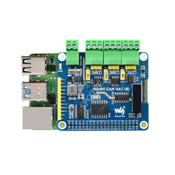
Raspberry Pi RS485 CAN HAT (B) User Guide
Overview
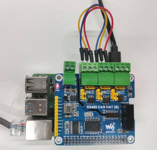
RS485 CAN HAT (B) is a HAT with RS485 and CAN communication functions developed by Waveshare for Raspberry Pi, with RS485 and CAN communication functions.
Features
- Standard Raspberry Pi 40PIN GPIO extension header, supports Raspberry Pi series boards
- With 1-ch CAN, the controller MCP2515 and CAN transceiver, convert SPI to CAN
- Adopts SC16IS752 + SP3485 dual-chip combination, converts SPI to RS485, data rate up to 921600bps
- Onboard power conversion circuit, supports 8~28V wide voltage power supply, can supply power to Raspberry Pi at the same time
- Onboard integrated power isolation, provides stable isolation voltage, and no additional power supply is required at the isolation end
- Onboard integrated digital isolation for signal isolation with high reliability, strong anti-interference, and low power consumption
- Onboard TVS (Transient Voltage Suppressor), effectively suppresses surge voltage and transient spike voltage in the circuit, lightning-proof & anti-electrostatic
- Onboard auto-recovery fuse and protection diodes, ensures the current/voltage stable outputs, provides over-current/over-voltage proof, improve shock resistance
- On-board 120Ω terminal resistor, enabled by jumper cap settings
- It can be wired via onboard terminals or pin headers, making wiring more convenient
- Breakout SPI control pins, for connecting with host control boards
Specification
| Expanded interface | 2-Ch RS485 + 1-Ch CAN |
|---|---|
| Communication Bus | SPI |
| CAN Controller | MCP2515 |
| CAN Receiver | SIT65HVD230DR/SN65HVD23D |
| CAN Baud Rate | ≦1Mbps |
| UART Expansion Chip | SC16IS752 |
| RS485 Receiver | SP3485 |
| RS485 Baud Rate | 300~921600 bps |
| Power Supply | External screw terminal or Raspberry Pi |
| External Voltage Range | DC 8~28V |
| Operating Voltage | 3.3V |
| Dimensions | 65 × 56.5 mm |
Interface
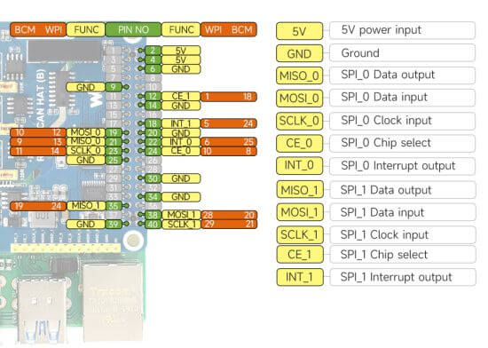
- CAN bus(CAN_0, control via SPI0)
| Func | BCM | Description |
|---|---|---|
| 5V | 5V | 5V power input |
| GND | GND | Ground |
| SCLK_0 | 11 (SCK) | SPI clock input |
| MOSI_0 | 10 (MOSI) | SPI data input |
| MISO_0 | 9 (MISO) | SPI data output |
| CE_0 | 8 (CE0)[1] | data/command selection |
| INT_0 | D25[2] | interrupt output |
- RS485 bus(control RS485_0 & RS485_1 via SPI1)
| Func | BCM | Description |
|---|---|---|
| 5V | 5V | 5V power input |
| GND | GND | Ground |
| SCLK_1 | D21 | SPI clock input |
| MOSI_1 | D20 | SPI data input |
| MISO_1 | D19 | SPI data output |
| CE_1 | D18 | data/command selection |
| INT_1 | D24[3] | interrupt output |
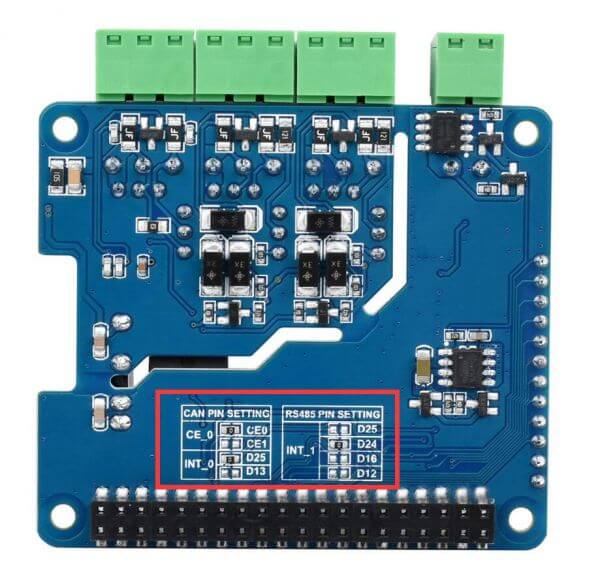
Default Solder Joint Switching Description
- ↑ CE_0 soldered to 8 (CE0) by default, you can change it to CE1 by modifying the 0R resistance on the back.
- ↑ Soldered to D25 by default, you can change it to D13 by modifying the 0R resistance on the back.
- ↑ Soldered to D24 by default, you can change it to D25/D16/D12 by modifying the 0R resistance on the back.
- The detailed soldering joint on the back is shown below:
Hardware Description
CAN Bus
The CAN module is to process all the reception and transmission of the CAN bus. When sending the report, the report will be loaded in the correct report buffer and control register first. With the SPI interface, you can set the corresponding bit or the enabled pin to send the report. Also, you can check the communication and errors by reading the corresponding register. It will check all the reports in the CAN bus, and then match them with the user-defined filters to make sure the report can be transmitted to one of the receiving buffers.
As the Raspberry Pi cannot support CAN bus, you must use the CAN controller with SPI interface to match with a receiver to finish the CAN function.
Microchip Technology's MCP2515, a CAN protocol controller, totally supports CAN V2.0B specification and can send and receive standard and extended data frames as well as remote frames.
The MCP2515 comes with two acceptance mask registers and six acceptance filter registers that filter out unwanted packets, thus reducing the overhead of the main microcontroller (MCU). The MCU is connected to the device through the SPI interface, that is, the Raspberry Pi connects the chip through the SPI interface, and for the Raspberry Pi to use the chip, it does not need to write a driver, just open the core driver in the device tree to use.
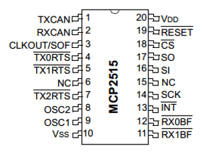
For more details, please refer to the datasheet.
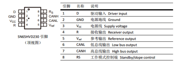
SN65HVD230 is a Texas Instruments 3.3V CAN transceiver suitable for serial communication with high communication rates, good interference immunity, and high-reliability CAN buses.
SN65HVD230 has three different operating modes: high speed, slope, and wait. Its operating mode control is possible via the Rs control pin. The output pin Tx of the CAN controller is connected to the data input D of the SN65HVD230, which can transfer the data sent by this CAN node to the CAN network; The receive pin Rx of the CAN controller is connected to R on the data output of the SN65HVD230 for receiving data.
RS485 Bus
This product uses SC16IS752 as the control chip, and SC16IS752 is a dual-channel high-performance UART expansion chip supporting SPI and I2C communication. This module uses an SPI interface, onboard power isolation, ADI magnetical isolation, TVS (transient voltage suppression transistor), reset-up fuse and protection diode, and automatic transceiver conversion circuitry. It can effectively suppress the surge voltage and transient peak voltage in the circuit, lightning protection and anti-static, anti-overcurrent overvoltage, improve the ability to resist shock, and can carry out signal isolation, which has the advantages of high reliability, strong anti-interference, and low power consumption. The communication protocol is shown as below:
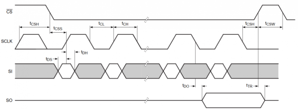
CS: Slave device chip selection. The chip is enabled when CS is in a low level.
SCLK: SPI communication clock.
MOSI/SI: SPI communication host sends and the slave device receives.
MIS0/SO: SPI communication host receives and the slave device sends.
Time order: CPHL = 0, CPOL = 0 (SPI0)
【Note】For more SPI communication information, you can search online.
The SP3485 is a low-power half-duplex transceiver that meets the specifications of RS485 serial protocols. It operates from a single +3.3V supply and uses half-duplex communication. The RO and DI terminals are the output of the receiver and the input of the driver, respectively; (RE) ̅ and DE are the receive and transmit enable sides, respectively, when (RE) ̅ is logic 0, the device is in the receiving state; When DE is logic 1, the device is in the transmit state; The A side and the B side are the receiving and transmitting differential signal terminals, respectively, when the A-B > +0.2V, the RO output logic 1; When A-B <-0.2V, the RO outputs logic 0. A matching resistor is added between the A and B terminals, and a 100Ω resistor is generally optional.
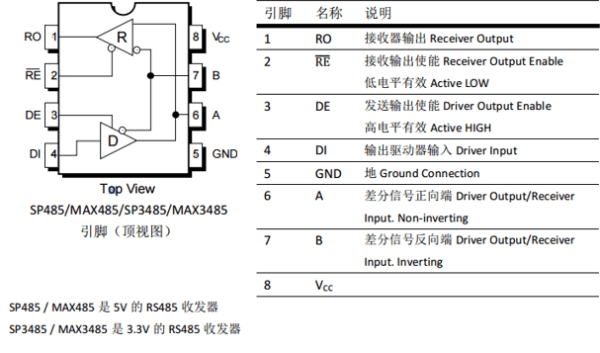
Among them: the RE and DE pins of the SP3485 chip are set to receive and send;
This module uses the automatic control of hardware to receive and send.
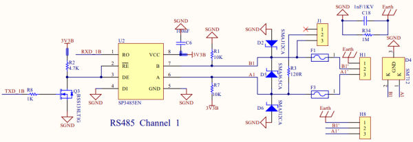
Data receiving: TXD is high at this time, and is in an idle state. At this time, the MOS is turned on, the RE pin of the SP3485 chip is low, the data reception is enabled, and the RO begins to receive data, and the data received by the 485AB port is transmitted to the MCU.
Data transmission: There will be a pull-down level in TXD indicating that data is being sent at the beginning, at which point the MOS cuts off, the DE pin is high, and data transmission is enabled. At this time, if the transmitted data is '1', the MOS will be on, although the reception will become a valid state, but because the chip is in a high-impedance state during the transmission phase, it still maintains the transmit state and transmits '1' normally.
Working With Raspberry Pi
Install Libraries
BCM2835
#Open the terminal of the Raspberry Pi and run the following command
wget http://www.airspayce.com/mikem/bcm2835/bcm2835-1.71.tar.gz
tar zxvf bcm2835-1.71.tar.gz
cd bcm2835-1.71/
sudo ./configure && sudo make && sudo make check && sudo make install
# For more information, please refer to the official website: http://www.airspayce.com/mikem/bcm2835/
WiringPi
#Open the terminal of the Raspberry Pi and run the following command
cd
sudo apt-get install wiringpi
#For Raspberry Pi systems after May 2019 (not done before the previous one) may require an upgrade:
wget https://project-downloads.drogon.net/wiringpi-latest.deb
sudo dpkg -i wiringpi-latest.deb
gpio -v
# Running gpio -v will appear version 2.52, if there is no description installation error

#The Bullseye branch system uses the following command:
git clone https://github.com/WiringPi/WiringPi
cd WiringPi
./build
gpio -v
# Running gpio -v will appear version 2.60, if there is no description installation error
python
sudo apt-get update
sudo apt-get install python-serial
sudo pip install python-can
Install python3 library:
sudo apt-get update
sudo apt-get install python3-pip
sudo pip3 install RPi.GPIO
sudo apt-get install python3-serial
Driver Configuration
Please insert the module into the Raspberry Pi and change the start-up script "config.txt".
sudo nano /boot/config.txt
Add the following content to the last command:
dtparam=spi=on
dtoverlay=mcp2515-can0,oscillator=16000000,interrupt=25,,spimaxfrequency=1000000
dtoverlay=sc16is752-spi1,int_pin=24
Save and exit, and reboot the Raspberry Pi:
sudo reboot
Check Whether The Configuration Is Correct
After rebooting, the drivers of SC16IS752 and mcp251x will be loaded into the system kernel, run the command to check whether the initialization is successful:
dmesg | grep -i '\(can\|spi\)'

If you do not connect to the module, you may be prompted as follows:
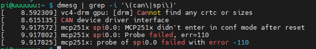
Please check if the module is connected, whether the SPI, and MCP2515 kernel is enabled and whether it is restarted.
RS485
Also, you can run the following commands:
ls /dev
Check whether the RS485 bus is correctly configured. If the configuration is correct, the following devices will be added:
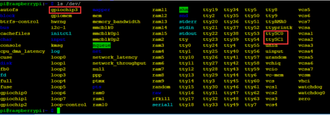
In the 2020-05-27 Raspberry Pi system gpiochip3 has become gpiochip2 without it.
CAN
Open CAN
sudo ip link set can0 up type can bitrate 1000000
sudo ifconfig can0 txqueuelen 65536
- For more CAN kernel commands, please refer to:
https://www.kernel.org/doc/Documentation/networking/can.txt
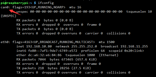
- Check ifconfig:
ifconfig

How To Use CAN
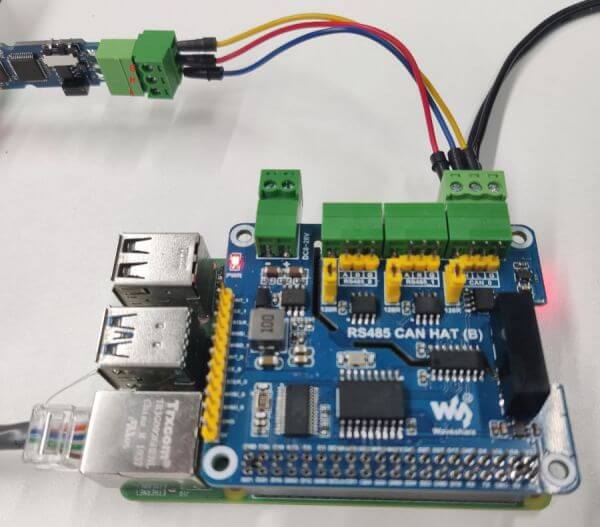
Hardware Connection
This demo uses a Raspberry Pi, an RS485 CAN HAT (B) module and a USB-CAN-A module.
Python and c language programs are provided.
Simple Test
- Open CAN
sudo ip link set can0 up type can bitrate 1000000
sudo ifconfig can0 txqueuelen 65536
- For more CAN kernel commands, please refer to:
https://www.kernel.org/doc/Documentation/networking/can.txt
- Check ifconfig:
ifconfig
- Install can-utils:
sudo apt-get install can-utils
- Receive:
The command for inputting the receiving data in the terminal:
candump can0
The receiving tool is blocked. When running the tool without parameters, it will always be in the receiving state. Use Ctrl+C to exit.
A description of the parameters of the tool can be used:
candump -h
- Sending
Input the command for sending the data in the terminal:
cansend can0 000#11.22.33.44
The result is as shown below: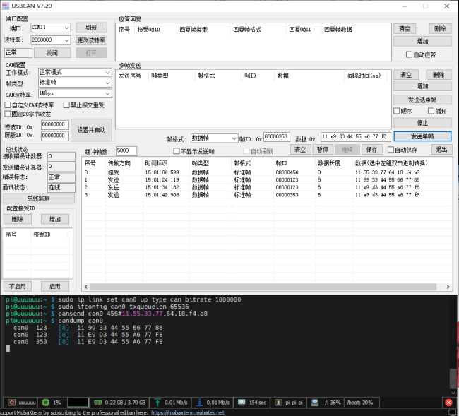
- Self-test
Input the command in the terminal:
cangen can0 -I i -L 8
#-I sets the device ID, 'i' is the incremental mode; -L sets the data length
At this time, data with the increasing device ID, length 8, and random content will be continuously sent to CAN. At the same time, this command enables loopback mode by default and can be run in another terminal window:
candump can0
After running, you can also receive the data sent above: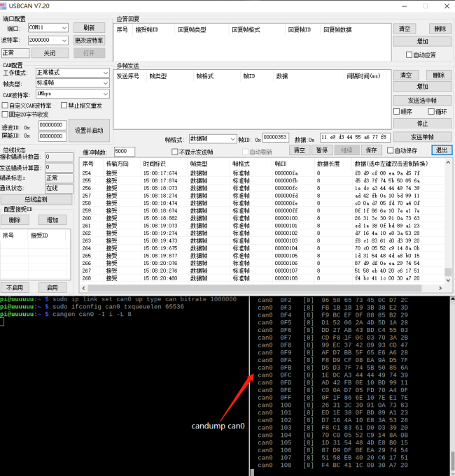
After the test is over, you can use Ctrl+C in the two terminals to end the operation.
Download The Demo
Run in the terminal of the Raspberry Pi:
sudo apt-get install unzip
wget https://www.waveshare.com/w/upload/9/92/RS485_CAN_HAT_B.zip
unzip RS485_CAN_HAT_B.zip
sudo chmod 777 -R RS485_CAN_HAT_B/
cd RS485_CAN_HAT_B
C
Note:
- Please make sure the hardware connection is correct, that is, H-H and L-L connection.
- The baud rate of both sides must be the same and the default demo setting is 1Mbps.
- If the data loses frame due to the long time transmission, you can try to lower the baud rate.
- Send, the Raspberry Pi open the terminal, and run:
cd RS485_CAN_HAT_Code/CAN/wiringPi/send/
make clean
make
sudo ./can_send
- Blocking receiving, the Raspberry Pi opens the terminal and runs:
cd RS485_CAN_HAT_Code/CAN/wiringPi/receive/
make clean
make
sudo ./can_receive
The receiving program is blocked until the data is read.
Note: This program can only receive data whose frame ID is 123. If you need to receive other ID data, you can modify the program yourself. 
Take USB to CAN debug tool as an example: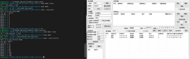
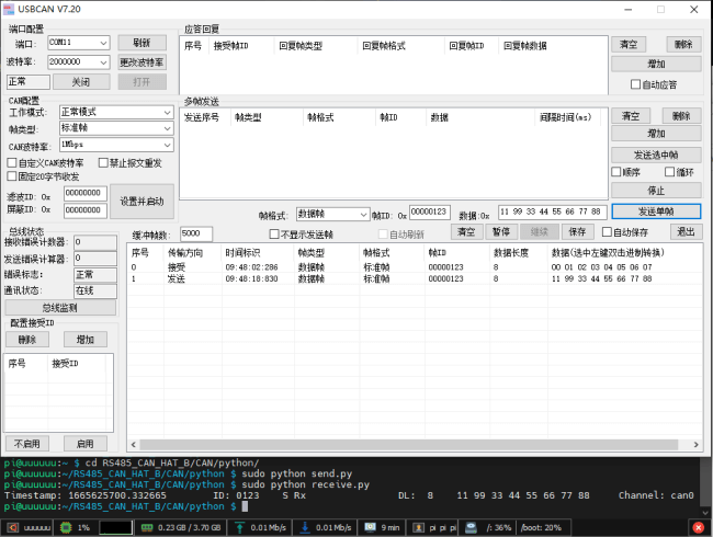
Python
The Raspberry Pi opens the terminal and runs:
#the sending terminal:
sudo python can_send.py
cd RS485_CAN_HAT_B/CAN/python/
#Run the receiving program before sending the data from your computer
sudo python can_reveive.py
How to use RS485
Hardware Connection
Detailed connection:
- Running the C and python demo requires an additional USB TO RS485 bidirectional converter to channel 1 to see the effect.
- In Python, test.py requires a connection between channel 1 and channel 2.
| Func | BCM | Description |
|---|---|---|
| 5V | 5V | 5V Power Input |
| GND | GND | Ground |
| SCLK_1 | D21 | SPI clock input |
| MOSI_1 | D20 | SPI data input |
| MISO_1 | D19 | SPI data output |
| CE_1 | D18 | Data/command selection |
| INT_1 | D24 | interrupt output |
Test
- Download and run the test demo
sudo apt-get install p7zip-full
wget https://www.waveshare.com/w/upload/9/92/RS485_CAN_HAT_B.zip
unzip RS485_CAN_HAT_B.zip
sudo chmod 777 -R  RS485_CAN_HAT_B.zip
cd RS485_CAN_HAT_B/
C Program
cd c
make clean
make
sudo ./main
The demonstration here is: The connection between channel 1 of RS485_0 and the A.B connection of USB TO RS485 is as follows: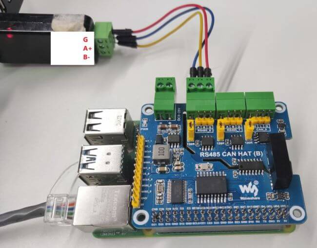
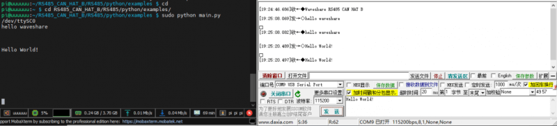
Connect the USB TO RS485 to your computer, open the serial port assistant, choose the corresponding serial port, and set the baud rate as 115200.
- Execute the C program, the module returns the data that the computer sends to execute the C program, as shown below:
(Note: You need to add a carriage return and line feed, otherwise the data will not be returned; the program directory of the example is based on the actual.)
Python
cd python
cd examples
sudo python3 main.py
The hardware connection of this program and the C program is the same as the phenomenon:
You can try the following test demo when you don't have USB TO RS485:
- Connect the A, B of channel 1 to the A, B of channel 2.
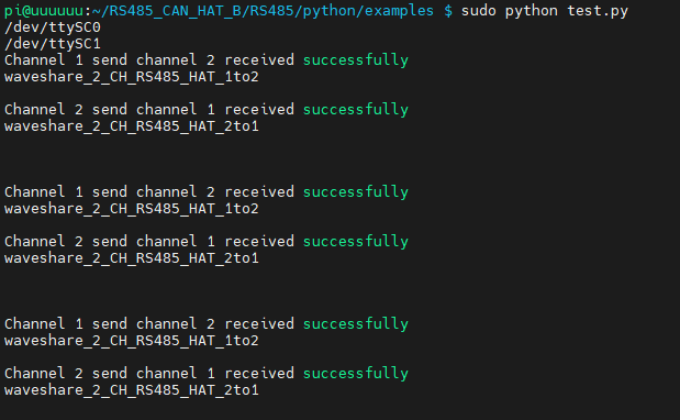
- Run test.py and you can get the result below:
sudo python3 test.py

Modbus Application Example
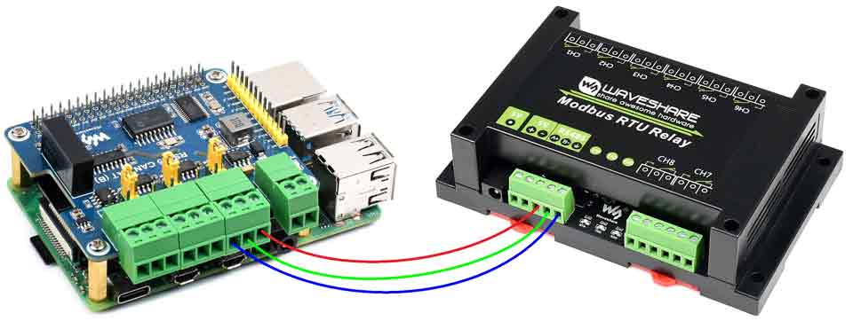
This example requires a Raspberry Pi, an RS485 CAN HAT, and a Mobus RTU Relay.
Hardware Connection
- Install the HAT to the Raspberry Pi, and connect the RS485 interface of the HAT to the Modbus's RS485 interface by A-A and B-B.
- Power the Raspberry Pi and the Modbus module respectively.
Download Demo
wget https://www.waveshare.com/w/upload/b/ba/RS485_Modbus_RTU_Relay_Code.zip
- Enter the path after unzipping:
unzip RS485_Modbus_RTU_Relay_Code.zip
cd RS485_Modbus_RTU_Relay_Code/Modbus_RTU_Relay_Code/Python3
- Run the program
sudo python main.py
- After running the program, the relay relays are sequentially turned on from CH1 to CH8 and then turned off from CH1 to CH8 according to the number and loop continuously.
- For more programs, you can refer to Modbus RTU Relay module wiki and pay attention to change the serial port number of the program.