


- sales/support
Google Chat:---
- sales
+86-0755-88291180
- sales01
sales@spotpear.com
- sales02
dragon_manager@163.com
- support
tech-support@spotpear.com
- CEO-Complaints
zhoujie@spotpear.com
- Only Tech-Support
WhatsApp:13246739196
- Purchase/Shipping/Refund
WhatsApp:13424403025
Raspberry Pi Pico ESP32-S2 User Guide
Overview
This is a WiFi development board with compact size, plenty of peripheral interfaces, integrated low-power Wi-Fi System-on-Chip (SoC), and mass memory, supporting the Raspberry Pi Pico expansion board ecosystem. Equipped with a hardware crypto accelerator, RNG, HMAC, and Digital Signature module, it can meet the security requirements of the Internet of Things. Multiple low-power operating states to satisfy power requirements in IoT, mobile devices, wearable electronics, smart home, and other application scenarios, etc.
Features
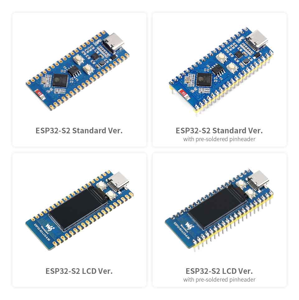
ESP32-S2 Standard Ver.
- Support Raspberry Pi Pico expansion board ecosystem to satisfy creative IoT application development
- Xtensa single-core 32-bit LX7 microprocessor, ESP32-S2FH4, support clock frequency up to 240 MHz
- Integrated 320KB SRAM, 128KB ROM, 8MB PSRAM, 4MB Flash memory
- Support IEEE802.11 b/g/n, on-board 2.4 GHz WiFi ceramic antenna, up to 150 Mbps data transfer rate
- USB-C connector, no more plug orientation problem
- On-chip integrated full-speed USB OTG interface, LCD interface (8-bit serial RGB/8080/6800), TWAI controller (ISO11898-1 compatible), capacitive sensor GPIO, temperature sensor, and RMT (TX/RX)
- On-board 1.8A current high-efficiency boost/buck DC-DC TPS63000 power supply IC
- Support a variety of low-power operating states for adjusting the optimal balance between communication distance, data rate, and power consumption, to meet the power requirements of various application scenarios
- Castellated module allows soldering direct to user-designed carrier boards
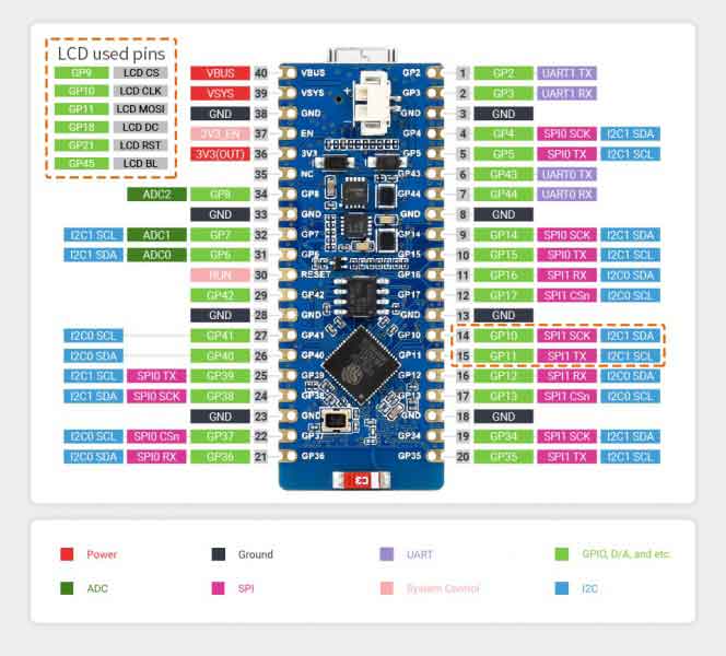
ESP32-S2 LCD
- All features of the ESP32-S2 Standard Ver.
- On-board 0.96inch 160×80 pixels 65K color IPS LCD display
- On-board single 3.7V lithium battery charge/discharge header, suitable for mobile IoT product design
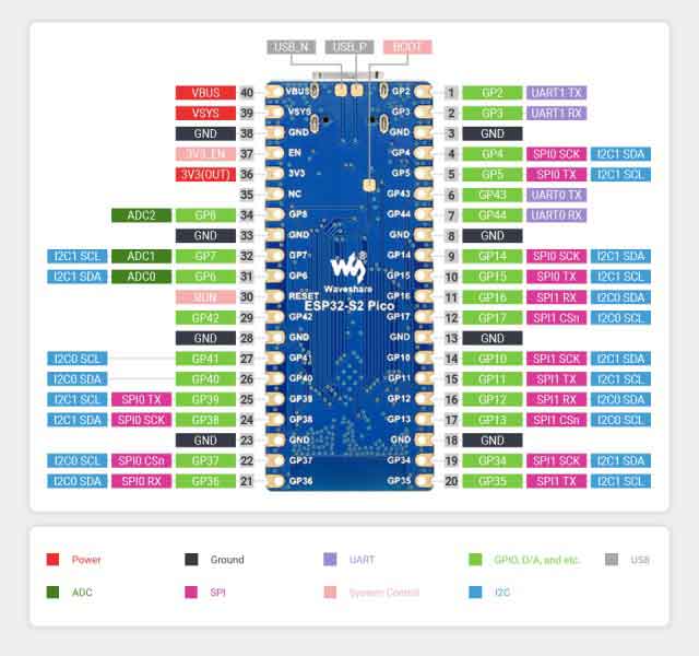
Pinout
ESP32-S2-Pico, ESP32-S2-LCD-0.96 bring out the same pins, all the pins can be set to SPI, I2C, UART, TWAI, AD/DA, I2S hardware functions through the powerful IO MUX of ESP32-S2,
- Putting default UART0 pin in a fixed position, do not recommend setting it to other functions
- ESP32-S2 has 2 x 8-bit DACs independent operating channel
- The USB pins of ESP32-S2(GPIO19, GPIO20) can be used for firmware downloading and serial debugging
- For more details, please check ESP32-S2 Datasheet, Chapter 3.10 Peripheral Pin Assignments, and the schematic
- ESP32-S2-Pico
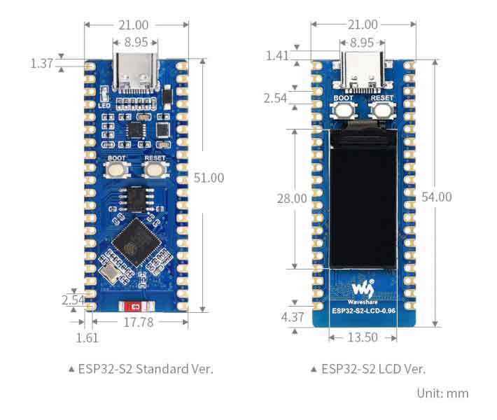
Dimensions
Development Languages
ESP32-S2-Pico, ESP32-S2-LCD-0.96 can use CircuitPython, MicroPython, C/C++(Arduino, ESP-IDF) to develop products rapidly. The following are the brief introductions of three development manners.
CircuitPython
As a programming language,CircuitPython is designed to simplify coding experimentation and learning on low-cost microcontroller boards, is an open-source derivative of the MicroPython programming language that aimed at students and beginners, and developed and maintained by Adafruit Industries.
- Circuitpython's related application development reference Development Documentation
- Github library of Circuitpython can be recompiled for custom development.
- Related firmware of Circuitpython for different ESP32-S2 core boards.
MicroPython
Micropython is a lean and efficient implementation of the Python 3 programming language that includes a small portion of the Python standard library and is optimized to run on microcontrollers and constrained environments.
- Micropython related application development reference Development Documentation
- Github library of Micropython can be recompiled for custom development
- Related firmware of Micropython on different ESP32-S2 core boards
C/C++ (Arduino, ESP-IDF)
Espressif official C/C++ library is easy for quick installment, please check the links below:
- Arduino development manual of ESP32-S2
- ESP-IDF development manual of ESP32-S2
Setup Environment
The environment is set under the Windows 10 system, the users can develop by using Arduino or ESP-IDF and Visual Studio Code as IDE. For Mac/Linux operating system users, please refer to the official instruction.
Arduino
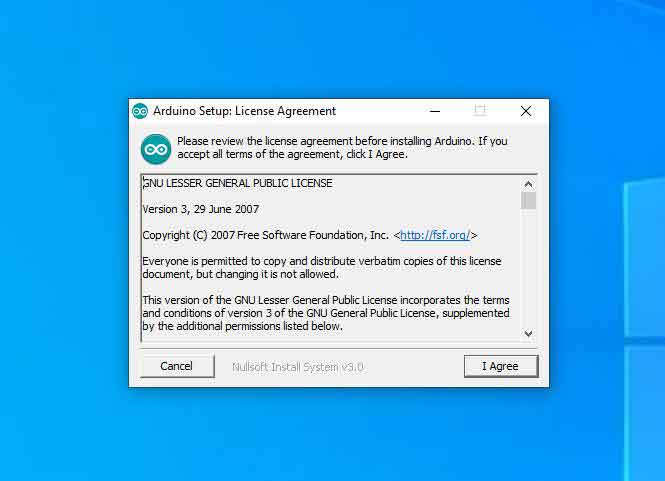
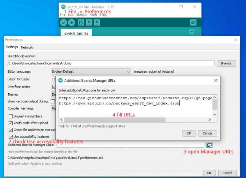
- 1. Downloading and installing Arduino IDE, please pay attention to the default configuration and the full English path.
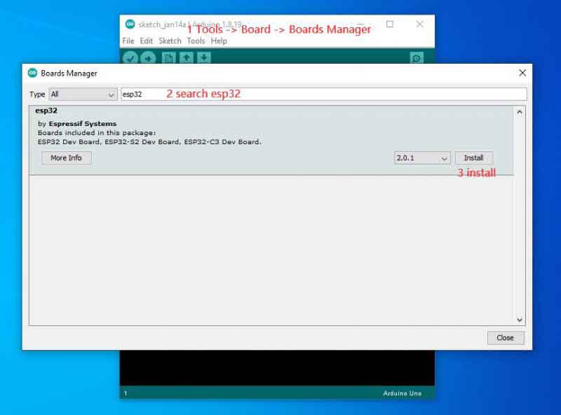
- 2, Arduino install ESP32 library, detail install process is shown below, please refer to related information for more information.
https://raw.githubusercontent.com/espressif/arduino-esp32/gh-pages/package_esp32_index.json
https://www.arduino.cn/package_esp32_dev_index.json
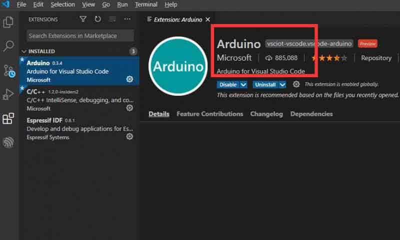
3, Open the VSCode, install Arduino and C/C++plugin (Microsoft Publisher)
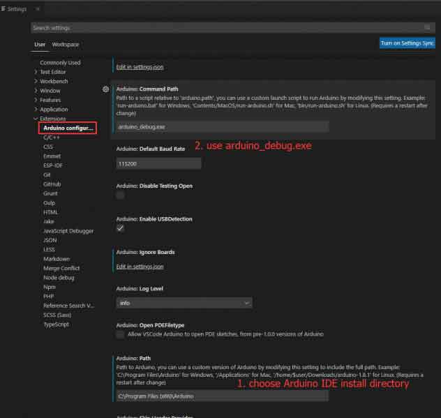
- 4, After installing plugin ,press F1 to enter Preferences Open Settings(UI),press Enter to find Arduino plugin setting.
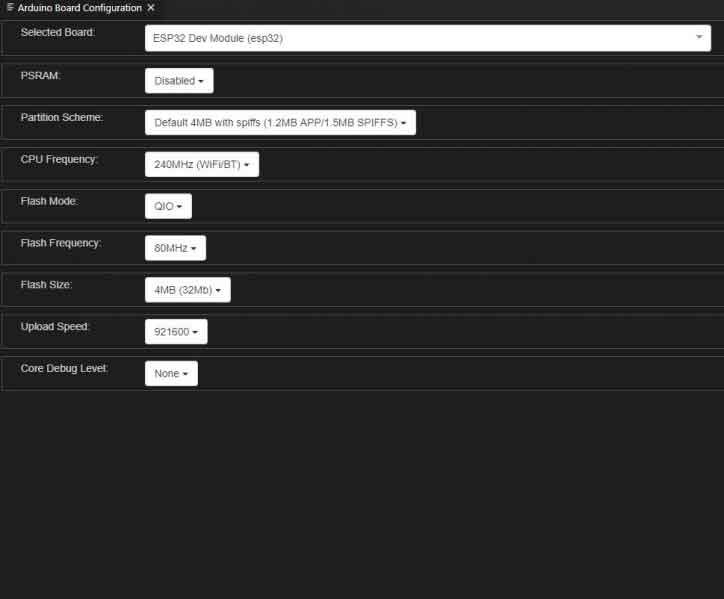
- 5, Press F1 to enter Arduino Board Config, then press Enter.
ESP-IDF
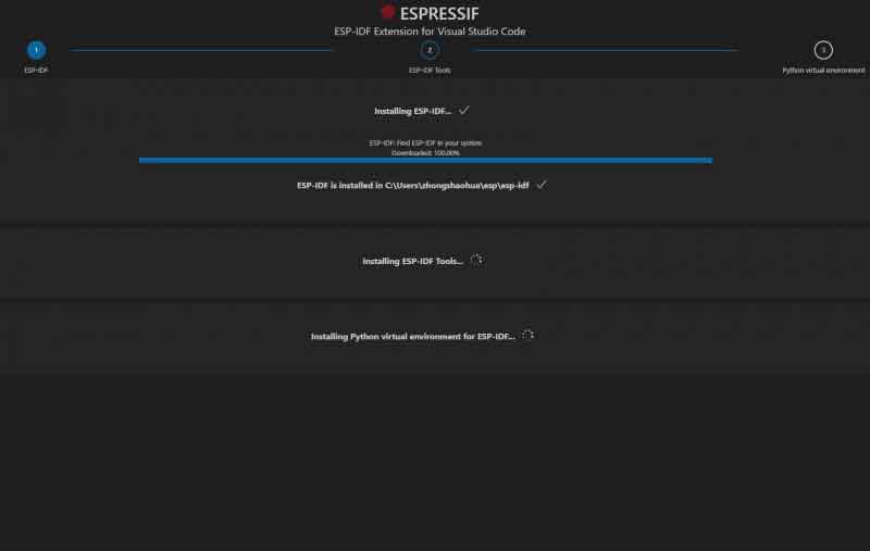
1, Download and install the latest offline version of esp-idf-tools-setup, and place in the full English path and use the default configuration (automatic installation of ESP-IDF, Python, Git, and setting environment variables), place the path of ESP-IDF elsewhere.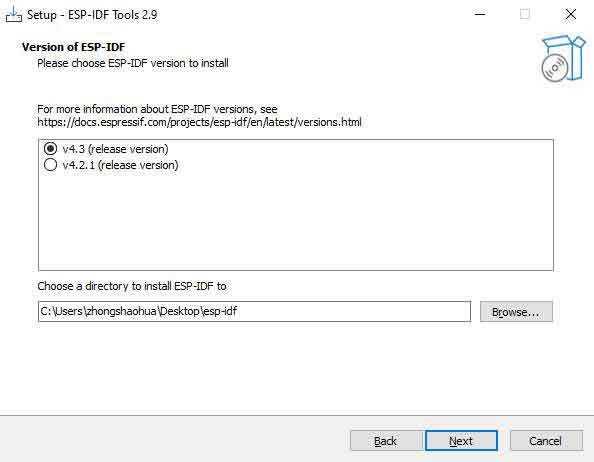
2, Download and install VS Code, place in the full English path, and use the default configuration.
3, Open VS Code,press Ctrl+P,enter ext esp-idf-extension to install configuration plugin.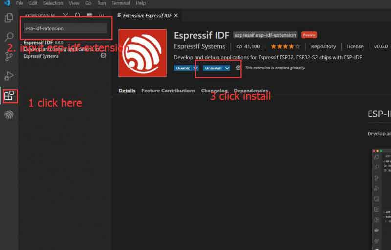
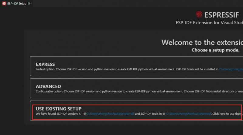
4, Press F1 in VSCode, enter Configure ESP-IDF extension to open the configure screen, and then choose USE EXISTING SETUP.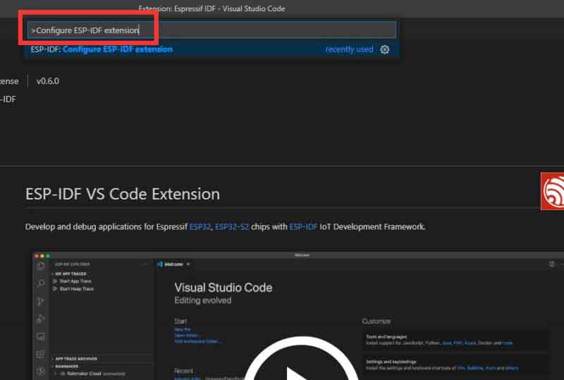

Hardware Connection
- Connect the Raspberry Pi Pico expansion board to ESP32-S2-Pico or ESP32-S2-LCD-0.96 in a stacked manner, be careful to avoid pin cross-use, such as serial expansion board of GPIO pins in the same position
- Do not block the antenna part of ESP32-S2-Pico or ESP32-S2-LCD-0.96, and it's necessary to adjust the board orientation if the Wifi signal is poor.
- To download the program, you need to press and hold the BOOT button and then press the RESET button to release, Or disconnect the USB, then press and hold the BOOT button to power on. At this time, the UART0 (GPIO43, GPIO44) and USB of ESP32-S2 can be used for flash programs
- ESP32-S2-Pico or ESP32-S2-LCD-0.96 will print the status information of ESP32-S2 when powered on by default. If you want to cancel, you need to write parameters to the register as shown in the figure below. Note that it cannot be restored after modifying.
Examples
This section combines Arduino, Raspberry Pi Pico expansion board, using AD/DA, SPI, I2C, WiFi, and other peripherals of ESP32-S2.
ADC/DAC
- Be careful to configure as shown in the following below, enable USB CDC, and select USB update mode
- If there is an error in the download as shown in the figure below, indicating that you need to manually reset the board to run the program after downloading.

- definite four AD, one DA macro, initialize the DA value of 127, and the USB serial output in the setup() function.
#define adc0 6
#define adc1 7
#define adc2 8
#define adc3 1
#define dac_pin 17

uint16_t adc_Value = 0;    // variable to store the value coming from the sensor
uint8_t dac_value = 127; //DA output value

void setup() {
  // put your setup code here, to run once:
  HWSerial.begin(115200);
  HWSerial.setDebugOutput(true);

  USB.onEvent(usbEventCallback);
  USBSerial.onEvent(usbEventCallback);

  USBSerial.begin();
  USB.begin();

  delay(4000);
//  USBSerial.printf("Setup done");
}
- DA increases 1 every 5 seconds and loops from 0 until 255. Use one of the AD pins to connect DA to detect the operation of DA. Lines 28 to 30 are battery voltage detection.
UART
- Need to select configuration options as shown in AD_DA demo download, enable USB CDC, and select USB update mode
- If there is an error message in the download, as shown in the AD_DA demo download, and it needs to be reset manually after downloading to run the program.
- UART demo combined with Pico-GPS-L76B to read NMEA, parse and convert the coordinate system and output, etc.
- Codes
- Include NMEA0183 library, instantiate NMEA0183Msg, NMEA0183, specify the pin of serial 1
- Specify the NMEA0183 data stream serial and baud rate in the NMEA0183.Begin() function, initialize the USB serial function, The loop() function polls the NMEA0183 data stream and then receives it
SPI
- You need to select the configuration, as shown in the AD_DA routine download, enable USB CDC, and select update mode
- If there is an error message in the download, as shown in the AD_DA demo download, and it needs to be reset manually after downloading to run the program.
- This example tests the LCD of ESP32-S2-LCD-0.96 and scans WiFi hotspot information and then prints it
- Codes
Initiate USB serial and the STA mode of Wifi in setup(), turn on the LCD display in the loop() function, and print out the scanned WiFi information of the USB serial.