


- sales/support
Google Chat:---
- sales
+86-0755-88291180
- sales01
sales@spotpear.com
- sales02
dragon_manager@163.com
- support
tech-support@spotpear.com
- CEO-Complaints
zhoujie@spotpear.com
- Only Tech-Support
WhatsApp:13246739196
- Purchase/Shipping/Refund
WhatsApp:13424403025
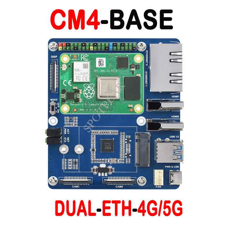
Raspberry Pi CM4-DUAL-ETH-4G/5G-BASE User Guide
Overview
This is a dual Gigabit ethernet 5G/4G base board, which is designed for Raspberry Pi Compute Module 4. It is suitable for evaluating the Raspberry Pi CM4 or being integrated into end products.
Notices
- DO NOT hot-plug any devices except the USB and HDMI.
- Please check the FAN voltage before connecting the cooling fan. The BASE board supports a 12V cooling fan by default, if you want to use a 5V cooling fan, please change the FAN_VCC resistor.
- DO NOT connect other devices while writing CM4 via Type C interface for stable working.
- 5V/2.5A or higher power supply is recommended for proper working.
Specifications
| CM4 SOCKET | suitable for all variants of Compute Module 4 |
| NETWORKING | Dual Gigabit Ethernet RJ45 |
| M.2 B KEY, for connecting 5G / 4G module | |
| Nano-SIM card slot, supports standard Nano-SIM card for 5G/4G/3G/2G communication | |
| USB | USB 3.2 Gen1 × 2 |
| PIN HEADER | Raspberry Pi 40PIN GPIO header |
| DISPLAY | MIPI DSI port (15pin 1.0mm FPC connector) |
| CAMERA | MIPI CSI-2 port × 2 (15pin 1.0mm FPC connector) |
| VIDEO | HDMI × 2, supports 4K 30fps output |
| RTC | Real-time clock with a battery socket and ability to wake Compute Module 4 |
| STORAGRE | MicroSD card socket for Compute Module 4 Lite (without eMMC) variants |
| FAN HEADER | 5V/12V (12V by default), allows speed adjustment and measurement |
| POWER INPUT | 5V/2.5A |
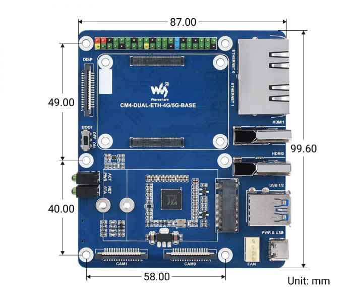
| DIMENSIONS | 99.6 × 87.0mm |
Dimensions
Writing Image
- Write Image for Compute Module Boards eMMC version
- Write Image for Compute Module Boards Lite version
4G/5G
To work with 4G/5G, you need to connect a wireless module to the M.2 B KEY for featuring corresponding functions. M.2 B KEY only extends USB3.0 interfaces, it doesn't support PCIe devices.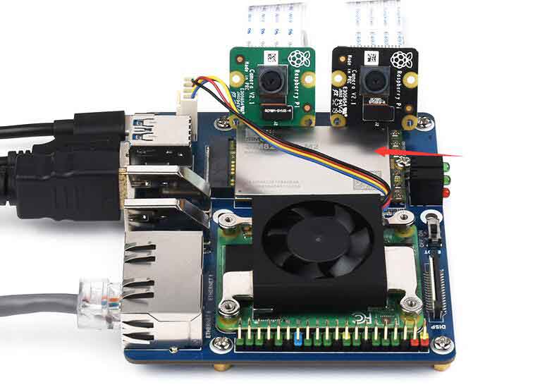
SIM card is required to work with the 4G/5G module
If you want to disable the 4G/5G module, you can set the GPIO6 to High and enable it again by setting the GPIO6 to Low.
The module requires about 30s to enable/disable the 4G/5G modules.
Status
| STA | NET | STATUS |
|---|---|---|
| ON | OFF | Shutdown or Stating |
| ON | ON | Searching network |
| ON | Flash | Working |
| OFF | Flash/ON | Shutting down |
Before you configure the 4G/5G module, please make sure that the module is working normally.
Configure 5G Modules
- Please refer to SIM8200EA-M2_5G_HAT
Configure 4G Modules
- Install minicom
sudo apt-get install minicom
- Run the minicom to configure moudules
sudo minicom -D /dev/ttyUSB2
- Configure the modules with the following command
AT+CUSBPIDSWITCH=9011,1,1
- Exit from the minicom and run the following command to assign IP for the usb0 (it maybe different if you connect other USB adapter)
sudo dhclient -v usb0
- If the network cannot connected properly, pleaes run theone of the following AT command to change the frequency and test it again.
AT+CNBP=0x0002000000400183,0x000001E000000000,0x0000000000000021
AT+CNBP=0x0002000000400180,0x480000000000000000000000000000000000000000000042000001E200000095,0x0000000000000021
AT commands
If your 4G modules cannot connect to network properly, please try to trobuleshoot by minicom and the AT commands.
sudo minicom -D /dev/ttyUSB2
- Common AT commands
| Command | Description | Return |
|---|---|---|
| AT | AT test | OK |
| ATE | ATE1 enable echo ATE0 disable echo | OK |
| AT+CGMI | Check manfacture | OK |
| AT+CGMM | Check module type | OK |
| AT+CGSN | Check SN | OK |
| AT+CSUB | Check module version | OK |
| AT+CGMR | Check firmware version | OK |
| AT+IPREX | Configure hardwara baud rate | +IPREX: OK |
| AT+CRESET | Reset module | OK |
| AT+CSQ | Check signal quanlity | +CSQ: 17,99 OK |
| AT+CPIN? | Check SIM status | +CPIN: READY |
| AT+COPS? | CHeck the current supplier | +COPS: OK |
| AT+CREG? | Check network status | +CREG: OK |
| AT+CPSI? | Check UE information | |
| AT+CNMP | Configure network mode: 2:Automatic 13:GSM only 38:LTE only 48 : Any modes but LTE ... .... | OK |
For more AT commands, please refer to: AT_Command_V2.00
You can also refer to:SIMCom
RTC FAN
- Note 1: Please connect the cooling fan before you power the whole device, otherwise, the control chip will be damaged!
- Note 2: Please check the voltage before you connect the cooling fan, it is default 12V.
To enable the I2C for controling the fan and the RTC, you need to add the line "dtparam=i2c_vc=on" on thw config.txt file
RTC is connected to i2c-10 with address 0x51(7bits)
FAN is connected to i2c-10 with address 0x2f(7bits)
sudo nano /boot/config.txt
Add the following lines to the end of the config.txt
dtparam=i2c_vc=on
dtoverlay=i2c-rtc,pcf85063a,i2c_csi_dsi
And then comment out the line dtparam=audio=on
#dtparam=audio=on
Save the file and reboot the system
sudo reboot
RTC test
1.Download the test demo.
Open the terminal of the Raspberry Pi, enter the following command:
sudo apt-get install p7zip-full
sudo wget https://www.waveshare.com/w/upload/4/42/PCF85063_code.7z
7z x PCF85063_code.7z -O./
cd PCF85063_code
2. Run the demo
C
Execute the following commands to compile and execute the test demo:
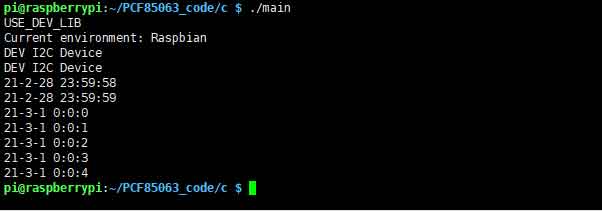
cd c
sudo make clean
sudo make -j 8
sudo ./main
And then you can check the running result as below:
Python
Enter the python/example directory:
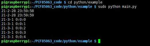
cd python/example
And then run the python demo, the demo can support python2/3
# python2
sudo python main.py
# python3
sudo python3 main.py
The running result is as below:
Using Hwclock
- Synchronize the system clock and the RTC
sudo hwclock -w
- Synchronize the hardware clock and the RTC
sudo hwclock -s
Note that it will be restore if the network is diabled
- Set hardware clock
sudo hwclock --set --date="9/8/2021 16:45:05"
- Check the hardware clock
sudo hwclock -r
- Check the version
sudo hwclock --verbose
FAN test
【Note】Please connect the fan first before connecting the power to the Board to complete! Please do not connect the fan to the Board when the board is powered on(the fan control chip is powered on), otherwise, it will be damaged!
There is not official seting method for the cooling, there is a third-party project for reference.
mkdir -p ~/src
cd ~/src
git clone https://github.com/neg2led/cm4io-fan.git
cd cm4io-fan
sudo chmod 777 install.sh
sudo  ./install.sh
CSI DSI
CSI and DSI are disabled by default. When using the camera and DSI, it will occupy three I2C devices: I2C-10, I2C-11, and I2C-0.
- Open a terminal and run the following commands:
 sudo apt-get install p7zip-full
 wget https://www.waveshare.com/w/upload/4/41/CM4_dt_blob.7z
 7z x CM4_dt_blob.7z -O./CM4_dt_blob
 sudo chmod 777 -R CM4_dt_blob
 cd CM4_dt_blob/
 #If you want to use both cameras and DSI0
 sudo  dtc -I dts -O dtb -o /boot/dt-blob.bin dt-blob-disp0-double_cam.dts
 #If you want to ue both cameras and DSI1
 sudo  dtc -I dts -O dtb -o /boot/dt-blob.bin dt-blob-disp1-double_cam.dts
- And then connect the cameras and DSI display
1: Please power off the IO Board first before your connection.
2: Connect the power adapter after connecting the cameras and DSI display
3: Wait a few seconds before the screen boot up.
4: If the DSI LCD cannot display, please check if you have added /boot/dt-blob.bin. If there already has the dt-blob.bin, just try to reboot.
5: The camera needs to be enabled by raspi-config, enter sudo raspi-config on the terminal, choose Interfacing Options->Camera->Yes->Finish-Yes and reboot the system
- Test the Cameras:
Test camera0:
sudo raspivid -t 0 -cs 0
Test camera1:
sudo raspivid -t 0 -cs 1
For more information about the CSI camera and DSI display, please refer to: