- sales/support
Google Chat:---
- sales
+86-0755-88291180
- sales01
sales@spotpear.com
- sales02
dragon_manager@163.com
- support
tech-support@spotpear.com
- CEO-Complaints
zhoujie@spotpear.com
- Only Tech-Support
WhatsApp:13246739196
- Purchase/Shipping/Refund
WhatsApp:13424403025
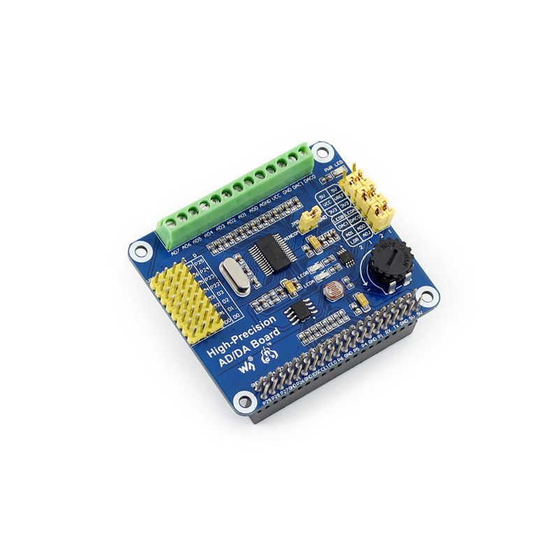
Raspberry Pi High-Precision AD/DA Board User Guide
Introduction
Raspberry Pi AD/DA Expansion
Basic operation of Raspberry Pi
Before using the module with Raspberry Pi, such basic operations are required:
- Using Raspberry Pi image
- Using Linux Terminal
If you have already known them, please skip this section directly.
How to use Raspberry Pi image
- Download the Raspbian image from https://www.raspberrypi.org/downloads/
- Unzip the downloaded file and get an .img file.
- Run the software Win32DiskImager.exe then select the Image File (the .img file) and Device(The TF Card Reader), click the button write to program the system image file. Note: The capability of TF card in used here should be more than 4GB. In this operation, a TF card reader is also required.
- Plug in the programmed TF card to the TF card socket on a Raspberry Pi, and then power up to
start the Raspbian OS. (System Configuration may be required for the first time boot up)
How to use the terminal of Raspberry Pi?
All the supported software should run under the Linux terminal. If you have a HDMI monitor, just connect it to the Pi directly then open the terminal at the GUI. If not, you can operate the terminal of Pi using SSH.
- Connect the Pi and a router via a network cable.
- Run the software PuTTY on the PC connected to the router, fill the IP address and Port of the Pi. You can get the Pi’s IP from the router. And the Port is 22 by default.
- Connection type is set to SSH.
- Click the button Open to enter the Pi’s terminal. At the first boot up, please input:
- User name: pi
- Password: raspberry
Getting started
The following API source codes should be run under the bcm2835 library. Click to download bcm2835-1.39 libraries or bcm2835-1.45 libraries, which can also be found from http://www.airspayce.com/mikem/bcm2835/
Analog to digital conversion
- Connect the High-Precision AD-DA Board to the Raspberry Pi.
- Jumper settings:
- Set the Power Supply to 5V: connect the pin 5V and VCC.
- Set the Reference Input Voltage to 5V: connect the pin 5V and VREF.
- Set the Potentiometer output as an Analog Input: connect the pin ADJ and AD0. Make sure the left side Sensor Interface AD0 is disconnected.
- Set the LDR output as an Analog Input: connect the pin LDR and AD1. Make sure the left side Sensor Interface AD1 is disconnected.
- Connect AINCOM to AGND. When using AD for differential measurements, the common input
- AINCOM does not need to be tied to ground.
- When using SSH for terminal control, please connect the network cable. The software PuTTY should be installed.
- Power up.
- Copy (using a USB drive as a carrier) the source code ADS1256 to the Raspbian OS. Note: the system will detect the USB drive directly under GUI, else if using SSH Connection, the USB drive cannot be operated until it is mounted to the Linux. Search the key words “Linux mount” for more details.
- Make the files: Enter the directory ADS1256, and execute
make
to compile it. - Execute
sudo ./ads1256_test
- Note: if it prompts command not found, please use
chmod +x ads1256_test
to add execute permission.
- Note: if it prompts command not found, please use
- Block the LDR from light and then the voltage of channel AD1 will be changed.
- Turn the potentiometer and the voltage of channel AD0 will be changed.
- In the end, press Ctrl+C to suspend the current process.
Digital to analog conversion
- Connect the High-Precision AD-DA Board to the Raspberry Pi.
- Jumper settings:
- Set the Power Supply to 5V: connect the pin 5V and VCC.
- Set the Reference Input Voltage to 5V: connect the pin 5V and VREF.
- Connect the pin DA0 to LEDA, the pin DA1 to LEDB. Then the brightness of LEDA indicator will be changed according to the voltage output of DA0 and the brightness of LEDB indicator will be changed according to the voltage output of DA1.
- When using SSH for terminal control, please connect the network cable. The software PuTTY should be installed.
- Power up.
- Copy (using a USB drive as a carrier) the source code, DAC8532, to the Raspbian OS. Note: the system will detect the USB drive directly under GUI, else if using SSH Connection, the USB drive cannot be operated until it is mounted to the Linux. Search the key words “Linux mount” for more details.
- Make the files: Enter the directory DAC8532, and execute
make
to compile it. - Execute
sudo ./dac8532_test
- Note: if it prompts command not found, please use
chmod +x dac8532_test
to add execute permission.
- Note: if it prompts command not found, please use
- Expected result: the brightness of LEDA and LEDB changes gradually.
Interface Definition
| Pin | Symbol | Description |
|---|---|---|
| 1, 17 | 3.3V | Power supply (3.3V) |
| 2, 4 | 5V | Power supply (5V) |
| 3, 5, 7, 8, 10, 18, 22, 24, 26, 27, 28, 29, 32, 36, 38, 40 | NC | NC |
| 6, 9, 14, 20, 25, 30, 34, 39 | GND | Ground |
| 11 | DRDY | ADS1256 data ready output, low active |
| 12 | RESET | ADS1256 reset input |
| 13 | PDWN | ADS1256 sync/power off input, low active |
| 15 | CS0 | ADS1256 chip select, low active |
| 16 | CS1 | DAC8532 chip select, low active |
| 19 | DIN | SPI data input |
| 21 | DOUT | SPI data output |
| 23 | SCK | SPI clock |
| 31, 33, 35, 37 | GPIO | extend to sensor interface |