- sales/support
Google Chat: zj734465502@gmail.com
- sales
+86-0755-88291180
- sales01
sales01@spotpear.com
- sales02
dragon_manager@163.com
- support
services01@spotpear.com
- CEO-Complaints
manager01@spotpear.com
- sales/support
WhatsApp:13246739196
- HOME
- >
- ARTICLES
- >
- Common Moudle
- >
- ESP
ESP32-S3-Touch-LCD-1.28 User Guide
Document
- Schematic
- arduino-esp32
- ESP-IDF
- MicroPython development documentation
- ESP32 Arduino Core's documentation
Demo
Software
Datasheet
Introduction
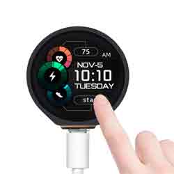
The ESP32-S3-Touch-LCD-1.28 (hereinafter referred to as "the development board") is a low-cost, high-performance microcontroller development board designed by Waveshare. It features a 1.28-inch capacitive touch LCD screen, a lithium battery charging chip, a six-axis sensor (three-axis accelerometer and three-axis gyroscope), and other peripherals. The board is based on the ESP32-S3R2, which is a system-on-chip (SoC) integrated with low-power Wi-Fi and BLE 5.0. It also includes an external 16MB Flash and 2MB PSRAM. The SoC features hardware encryption accelerators, RNG, HMAC, and digital signature modules, meeting the security requirements of the Internet of Things (IoT). Its various low-power operating modes are suitable for power requirements in IoT, mobile devices, wearable electronics, smart home applications, and other scenarios.
Features
- Equipped with Xtensa® 32-bit LX7 dual-core processor, up to 240MHz main frequency.
- Supports 2.4GHz Wi-Fi (802.11 b/g/n) and Bluetooth® 5 (LE), with onboard antenna.
- Built-in 512KB of SRAM and 384KB ROM, with onboard 2MB PSRAM and an external 16MB Flash memory.
- Type-C connector, keeps it up to date, easier to use.
- Onboard 1.28inch capacitive touch display, 240×240 resolution, 65K color.
- Onboard QMI8658 6-axis IMU (3-axis accelerometer and 3-axis gyroscope) for detecting motion gestures.
- Onboard 3.7V lithium battery recharge/discharge header and 6 × GPIO pins via SH1.0 connector.
- Supports flexible clock, module power supply independent setting, and other controls to realize low power consumption in different scenarios.
- Integrated with USB serial port full-speed controller, GPIO pins allow flexible configuring pin functions.
Parameters
| LCD Parameters | |||
| Touch Chip | CST816S | Touch Interface | I2C |
| Display Chip | GC9A01A | Display Interface | SPI |
| Resolution | 240(H)RGB x 240(V) | Display Size | Φ32.4mm |
| Display Panel | IPS | Pixel Size | 0.135(H)x0.135(V)mm |
| IMU Parameters | |||
| Sensor | QMI8658C | ||
| Accelaeration Parameters | Resolution: 16-bit Range (Optional): ±2, ±4, ±8, ±16g | ||
| Gyrometer | Resolution: 16-bit Range (Optional): ±16, ±32, ±64, ±128, ±256, ±512, ±1024, ±2048°/sec | ||
Precautions
- It is a normal phenomenon that the touch sensitivity and accuracy on the edge of the round touch screen will be reduced.
- When using the development board, you need to pay attention to the ceramic antenna area and avoid the PCB board, metal, and plastic parts covering the ceramic antenna.
- Onboard high-efficiency charge/discharge power management chip ETA6096 and MX1.25 battery header, the current charging current is set to 1A, the user can replace the R15 resistor to change the charging current, access to the 3.7V lithium single-cell batteries. Please refer to the schematic diagram for more details, it is recommended that access to the 3.7V lithium single-cell batteries under 500mAH.
Hardware Description
Interface Description
- Type-C interface: using CH434P chip for USB to UART to connect the ESP32-S3's UART_TXD (GPIO43) and UART_RXD (GPIO44), which is for firmware burning and log printing. With the automatic download circuit, you can download the firmware directly after connecting the Type-C interface.
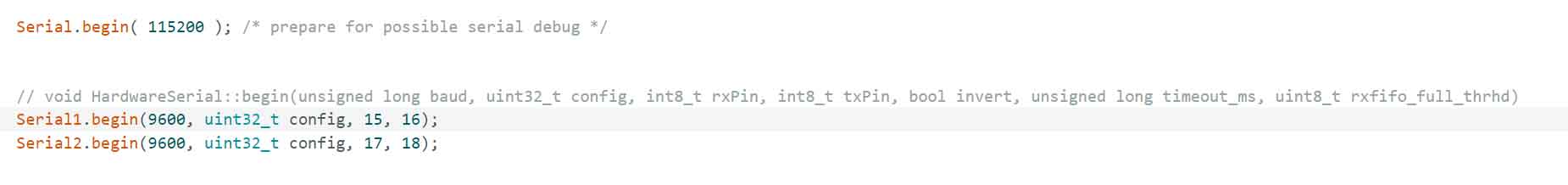
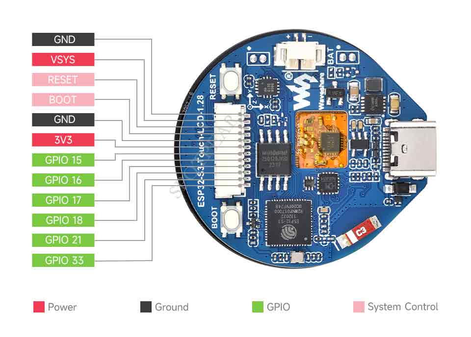
- SH1.0 connector: The development board leads to 6 GPIOs that can be used for other external connections, GPIO can be flexibly configured to I2C, SPI, and other peripheral functions, and VSYS can be directly input 5V to power the entire development board.
- LCD interface: Onboard a 1.28inch screen with4-wire SPI communication, the touch using I2C communication, and SPI rate can be improved to 80MHz. Touch using I2C communication. The development board uses GPIO2 to control backlight brightness, 2x MOS tubes to control the switch pad around the battery holder, connected to GPIO4 and GPIO5, and you can solder low-current devices with small currents such as vibration motors. For more details, please refer to the schematic diagram.
- I2C interface: The ESP32-S3 provides multiple hardware I2C. Currently, GPIO6 (SDA) and GPIO7 (SCL) pins are used for the I2C bus, mounting the QMI8658 six-axis inertial measurement unit and LCD touch control chip on the development board. Please refer to the schematic for more information.
- MX1.25 battery header: GPIO1 on the development board is used for measuring battery voltage. The battery voltage is divided using a series connection of 200K and 100K resistors, connected to GPIO1. The ESP32-S3 series has 2 channels of 12-bit SAR ADC measurement units. The code converts this into a voltage formula: 3.3 / (1<<12) * 3 * AD_Value.
| ESP32-S3R2 | LCD | SH1.0 | MX1.25 | QMI8658 | other |
| GPIO0 | BOOT0 | ||||
| GPIO1 | ADC | ||||
| GPIO2 | LCD_BL | ||||
| GPIO3 | INT2 | ||||
| GPIO4 | INT1 | MOSFET1_CS | |||
| GPIO5 | TP_INT | MOSFET2_CS | |||
| GPIO6 | TP_SDA | SDA | |||
| GPIO7 | TP_SCL | SCL | |||
| GPIO8 | LCD_DC | ||||
| GPIO9 | LCD_CS | ||||
| GPIO10 | LCD_CLK | ||||
| GPIO11 | LCD_MOSI | ||||
| GPIO12 | LCD_MISO | ||||
| GPIO13 | TP_RST | ||||
| GPIO14 | LCD_RST | ||||
| GPIO15 | GPIO15 | ||||
| GPIO16 | GPIO16 | ||||
| GPIO17 | GPIO17 | ||||
| GPIO18 | GPIO18 | ||||
| GPIO19 | |||||
| GPIO20 | |||||
| GPIO21 | GPIO21 | ||||
| GPIO33 | GPIO33 |
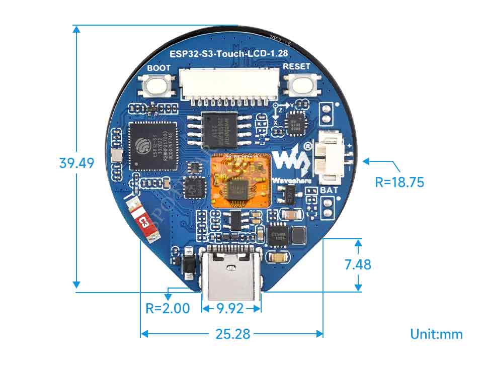
Dimensions
Environment Setting
The software framework for ESP32 series development boards is completed, and you can use CircuitPython, MicroPython, and C/C++ (Arduino, ESP-IDF) for rapid prototyping of product development. Here's a brief introduction to these three development approaches:
- Official C/C++ library installation:
- MicroPython is an efficient implementation of the Python 3 programming language. It includes a small subset of the Python standard library and has been optimized to run on microcontrollers and resource-constrained environments.
- You can refer to development documentation for MicroPython-related application development.
- The GitHub library for MicroPython allows for recompilation for custom development.
- Environment setting is supported on Windows 10. Users can select Arduino/Visual Studio Codes (ESP-IDF) as IDE to develop. For Mac/Linux, users can refer to official introduction.
ESP-IDF
Arduino
- Download and install Arduino IDE.
- Install ESP32 on the Arduino IDE as shown below, and you can refer to this link.
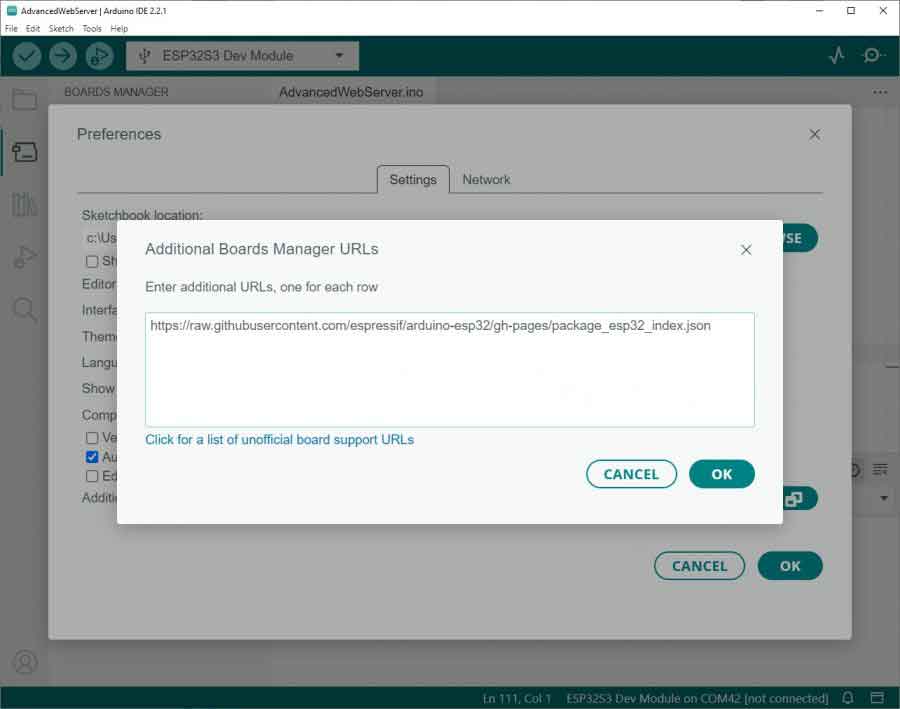
- Fill in the following link in the Additional Boards Manager URLs section of the Settings screen under File -> Preferences and save.
https://raw.githubusercontent.com/espressif/arduino-esp32/gh-pages/package_esp32_index.json
- Search esp32 on Board Manager to install, and restart Arduino IDE to take effect.
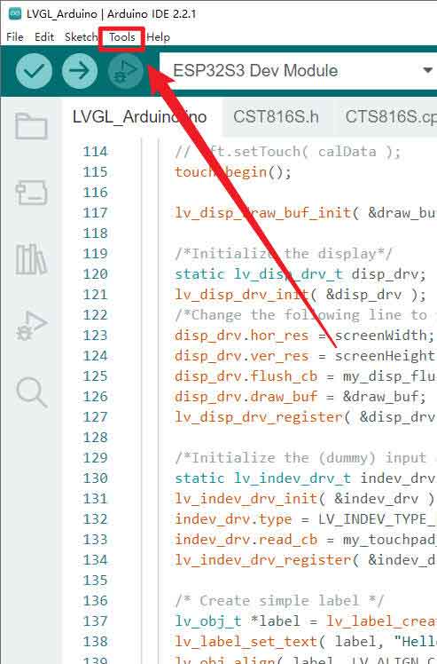
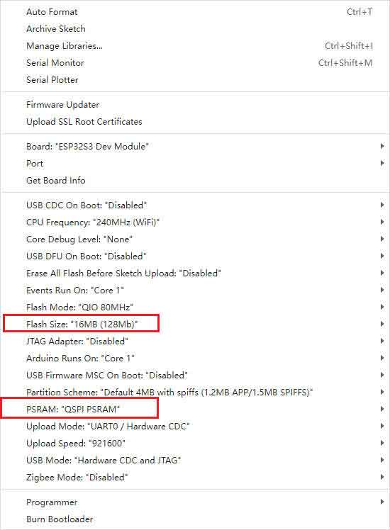
- Enter Arduino IDE, and select Tool -> 16MB Flash and enable QSPI PSRAM as shown below:
Library Installation
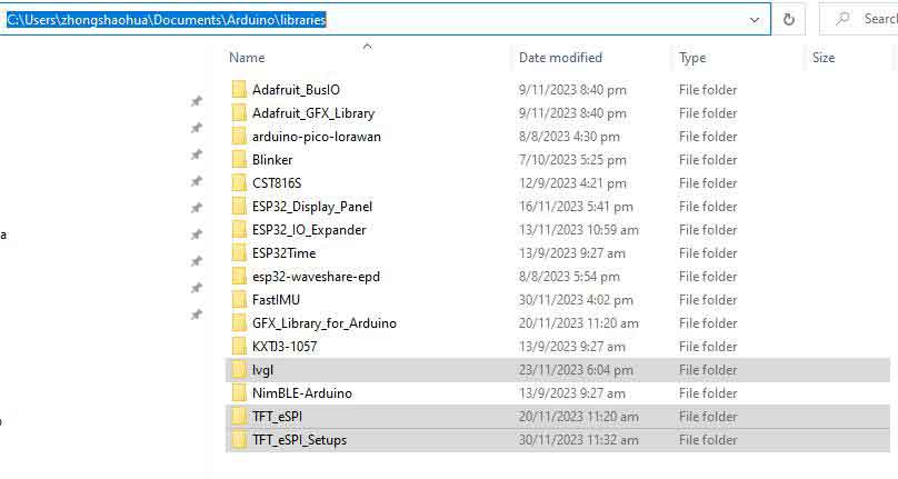
- After installing the TFT_SPI and LVGL libraries, configuration files are required. It is suggested to directly copy the TFT_eSPI_Setups, TFT_eSPI, and LVGL folders from the *Esp32-s3-touch-lcd-lib into the directory C:\Users\xxxx\Documents\Arduino\libraries. 'xxxx' represents your computer's username. Please be careful while identifying.
MicroPython
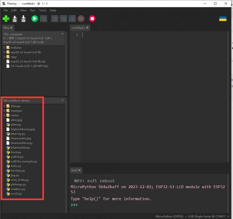
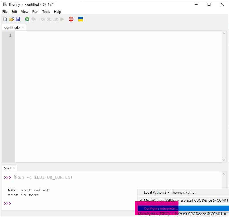
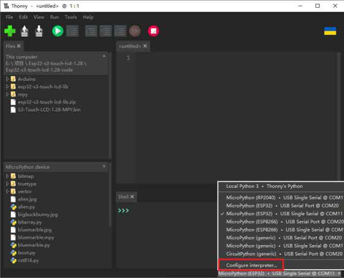
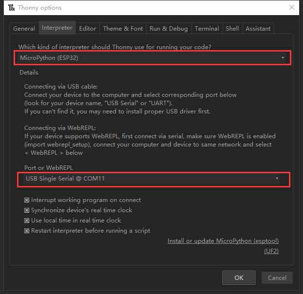
- 1. Download and install the latest Thonny, open ThonNY ide -> Configure interpreter... as shown below:
- 2. Connect the Type-C interface to the USB cable, find the device manager or the corresponding COM port, and download or run the program, please refer to the section on hardware connection.
- 3. Please ignore this step in this tutorial (Please skip to Step 4). According to the steps shown in the figure below to select the ESP32-S3 series of online MPY firmware download, the download will be cleared before the development of the board's Flash content, the entire download process lasts about 1 minute, MPY firmware can be downloaded from the official website!
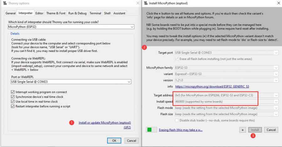
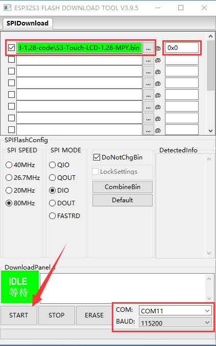
- 4. Currently, the development board is developed using customized firmware, which is in the sample demo zip. The firmware can refer to this link, and the firmware can be combined into a single file referring to #Download Other Firmwares. Please note that the address is 0x0.
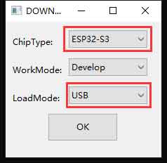
- After connecting ESP32-S3-Touch-LCD-1.28 to the PC, long-press BOOT key, single-click the RESET key, and then release the BOOT key to enable it to enter Download Mode.
- Select chip: ESP32-S3, download mode: USB.
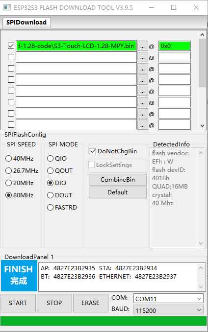
- Download S3-Touch-LCD-1.28-MPY.bin, and the downloaded address is 0X0. Select ESP32-S3-Touch-LCD-1.28's COM, click to start, and wait for it to program.
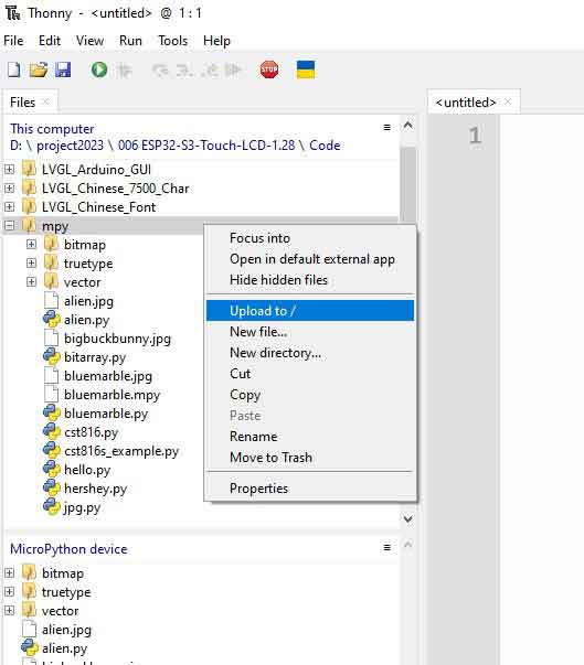
- 5. Program the firmware and press the RESET key, input the sample demo in the mpy directory to the development board as shown below:
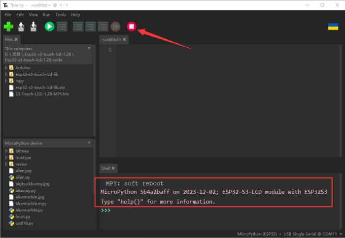
- Enter Thonny, select ESP32, and the corresponding COM port.
- Click the following button and you can see the shell output the sentence, which indicates the firmware of the development board can be used successfully.
- Upload the mpy file folder of the sample demo to the ESP32-S3-Touch-LCD-1.28.
For programming, you can refer to NicrPython Documentation and release note.
Download Other Firmwares
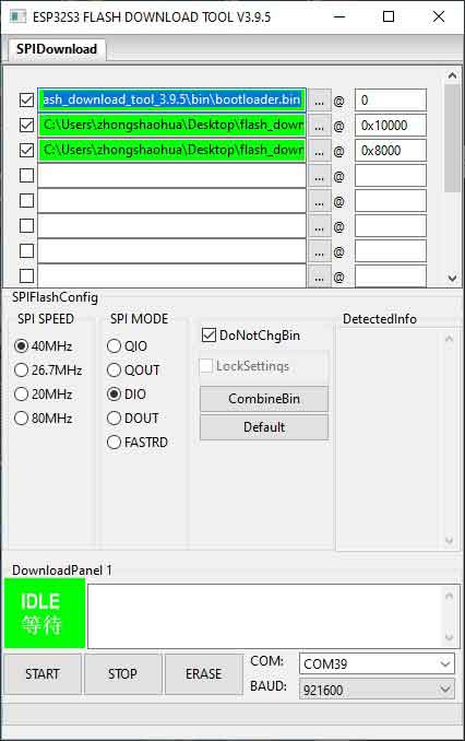
- If you use flash_download_tool_3.9.5 to download the firmware, please operate it according to the following picture. Note that the ESO32-S3 application firmware address is 0x10000, THE partition_tables.bin address is 0x8000, the bootloader.bin address is 0x0.
Sample Demo
Arduino
Arduino IDE Sample
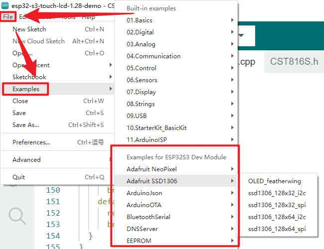
- For Arduino examples, please refer to Arduino-esp32 or File -> examples in the Arduino IDE, and for screen drivers, please refer to the sample demo.
esp32-s3-touch-lcd-1.28-demo
esp32-s3-touch-lcd-1.28-demo is for testing the screen, 6-axis sensor, BAT, and touch screen.
- The following is the demo effect:
After powering on, the screen will display white, red, green, and blue colors sequentially with a 2-second interval. Check the screen for any light leakage or black spots. If the screen changes too quickly to inspect, press the RESET button to restart the process.

a. Proceed to the sensor testing phase after the color display. After the colors, sensor data will be shown on the screen. When stationary, ACC_X and ACC_Y values should be below 200, ACC_Z around 1000, GYR_X, GYR_Y, GYR_Z values should be around 0 to 10. Any erratic readings might indicate damage to the six-axis sensor.

b. Connect the 3.7V lithium battery at this point. Normally, the BAT (V) value will decrease.

c. After checking the sensors, long-press the red area labeled 'LongPress Quit' to enter the touch test phase. Touch-dot programs in the white area of the Touch test.
Arduino_LVGL
- Arduino_LVGL sample is for displaying LVGL benchmark, music, and so on. For LVGL, you can refer to LVGL development tutorial.
- LVGL library is the callback function for displaying refreshing, refreshing the LVGL drawing buffer to TFT LCD.
void my_disp_flush( lv_disp_drv_t *disp_drv, const lv_area_t *area, lv_color_t *color_p )
Parameter:
     lv_disp_drv_t *disp_drv: LVGL: Provides the display driver structure pointer, including the display-related information and the function pointer. This function can be used to notify LVGL that the refresh is finished.
     const lv_area_t *area: LVGL: defines the pointer to area structure, indicating the area to be refreshed. This area is a rectangular area relative to the entire display screen.
     lv_color_t *color_p: LVGL: the defined color structure pointer, indicating the color data displayed in the refreshing area. This function is used to draw by writing this color data to the TFT buffer.
- The timer's callback function. The LVGL is notified of the past time by calling the LVGL function lv_tick_inc so that the LVGL can update its internal time state to handle time-related tasks such as animations, timers, etc. In the example, it is called every EXAMPLE_LVGL_TICK_PERIOD_MS milliseconds.
void example_increase_lvgl_tick(void *arg)
- The timer's callback function. The counter count, each call will be added to the counter, in the count reaches a certain value to trigger an operation, here is a simulation of the timer triggered 30 times after the restart operation, the specific behavior can be adjusted according to needs.
void example_increase_reboot(void *arg)
- Input device read callback function in the LVGL library to handle touchscreen input events:
void my_touchpad_read( lv_indev_drv_t * indev_drv, lv_indev_data_t * data )
Parameters:
     lv_indev_drv_t *indev_drv: the input device driver structure pointer of the LVGL. This structure includes the pointer of the input device driver structure. This structure includes information on the related input device and a callback function.
     lv_indev_data_t *data: the pointer of the input device data structure. This structure is for storing the status and data of the input device, including the current touch status (press or release) and the coordinates of the touch points.
Arduino_Chinese_Font
- Arduino_Chinese_Font is for displaying the LVGL built-in 1000 common Chinese fonts.
Arduino_Chinese_7500_Char
- Arduino_Chinese_7500_Char is for displaying LVGL's 7500 Chinese fonts. As the font file is large, the download of firmware time is relatively long.
Micropython
- mpy file includes the following examples, and you can click here to see more details.