


- sales/support
Google Chat:---
- sales
+86-0755-88291180
- sales01
sales@spotpear.com
- sales02
dragon_manager@163.com
- support
tech-support@spotpear.com
- CEO-Complaints
zhoujie@spotpear.com
- Only Tech-Support
WhatsApp:13246739196
- Purchase/Shipping/Refund
WhatsApp:13424403025
- HOME
- >
- ARTICLES
- >
- Common Moudle
- >
- UART Module
USB-TO-UART-I2C-SPI-JTAG Tutorial
Overview
Specification
| Parameter Name | Parameters | |
| Product Type | Industrial USB to UART/I2C/SPI/JTAG Converter | |
| Power Supply | USB port, 5V | |
| Operating Current | 55mA~65mA | |
| Operating Voltage | 3.3V/5V (select via onboard switch)) | |
| Operating Temperature | -40℃~85℃ | |
| Operating System | Linux, Windows 11 / 10 / 8.1 / 8 / 7 | |
| USB | Connector | USB-B |
| Interface Protection | Resettable fuse, ESD protection | |
| UART | Support Channels | 2 (the red DIP switch needs to be set to M0 mode) |
| Connector | 6PIN IDC connector | |
| Baudrate | 1200bps ~ 9Mbps (M0 mode) | |
| 1200bps ~ 7.5Mbps (M1/M2/M3 mode) | ||
| Hardware Flow Control | CTS & RTS | |
| I2C | Support Channels | 1 (the red DIP switch needs to be set to M1/M2 mode) |
| Interface Form | 12PIN IDC connector (the first 4 pins are I2C) | |
| SPI | Support Channels | 1 (the red DIP switch needs to be set to M1/M2 mode) |
| Interface Form | 12PIN IDC connector (the last 8 pins are SPI) | |
| JTAG | Support Channels | 1 (the red DIP switch needs to be set to M3 mode) |
| Connector | 12PIN IDC connector (the last 8 pins are JTAG) | |
Function Description
- USB TO UART/I2C/SPI/JTAG is a high-speed USB bus adapter device that supports USB to 2-ch UART, USB to 1-ch UART + 1-ch I2C + 1-ch SPI, USB to 1-ch UART + 1-ch JTAG.
- In Mode 0, the product provides 2x high-speed UART channels.
- In Mode 1 or Mode 2, the product provides 1x high-speed UART channel, 1x I2C interface (SCL and SDA lines), and 1 4-wire SPI interface (CS line, SCK line, SDI/MISO line, SDO/MOSI line).
- In Mode 3, the product provides a JTAG interface, supporting either a 4-wire or 5-wire interface (TMS, TCK, TDI, TDO, and TRST lines).
- In Mode 2, it operates as an HID plug-and-play device (Human Interface Device) and does not require drivers. Therefore, the newly added device may not be visible as a new port in the Device Manager.
- I2C and SPI are for Host/Master mode.
Mode Description
Please adjust the mode before powering on it.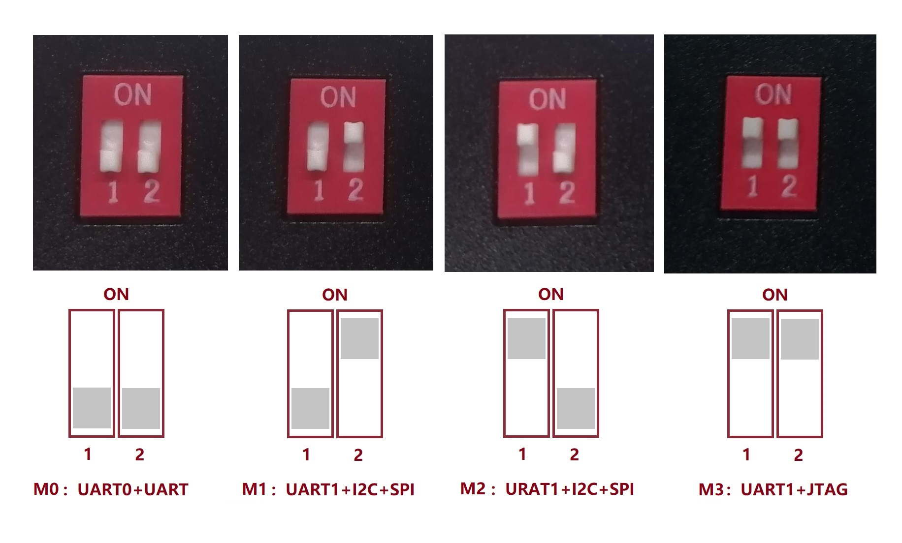
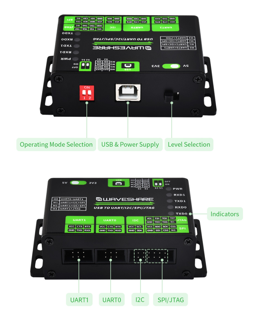
Interface Description
Windows
Environment Building
Driver Installtion
The installation provides CH341PAR and CH343SER (driver demo), and you can view the serial port and corresponding ports through the device manager.![]()
- Another viewing way: Go to Device Manager -> click "View" at the top -> "List Devices by Connection" -> select "ACPI x64 based computers" -> "PCI Express Root Complex" -> "Intel(R) USB 3.20 Scalable Host Controller - 1.20 (Microsoft)" (varies from computer to computer). "PCI Express Root Complex" -> "Intel(R) USB 3.20 Scalable Host Controller - 1.20 (Microsoft)" (may vary from computer to computer) -> "USB Root Hub (USB 3.0)" -> CH347 related devices can be found in "USB Composite Device" of multiple "Universal USB Hubs".
- Note: A serial port exists for all modes except mode 0.
Python IDLE Environment Building
- Install Python IDLE (Installation address: Python IDLE), please select and add to PATH when installing.
- Click "WIN + R", type cmd, enter pip install pyserial in the window and make sure the pyserial library is installed.
pip install pyserial
UART Interface Usage Demo
If you want to use two UART ports, you can switch to Mode0 and then connect to the PC.
UART Self-Transmission and Reception Communication in SSCOM
The following is using two serial ports of the product to perform self-transmission and reception. Please switch to mode0.
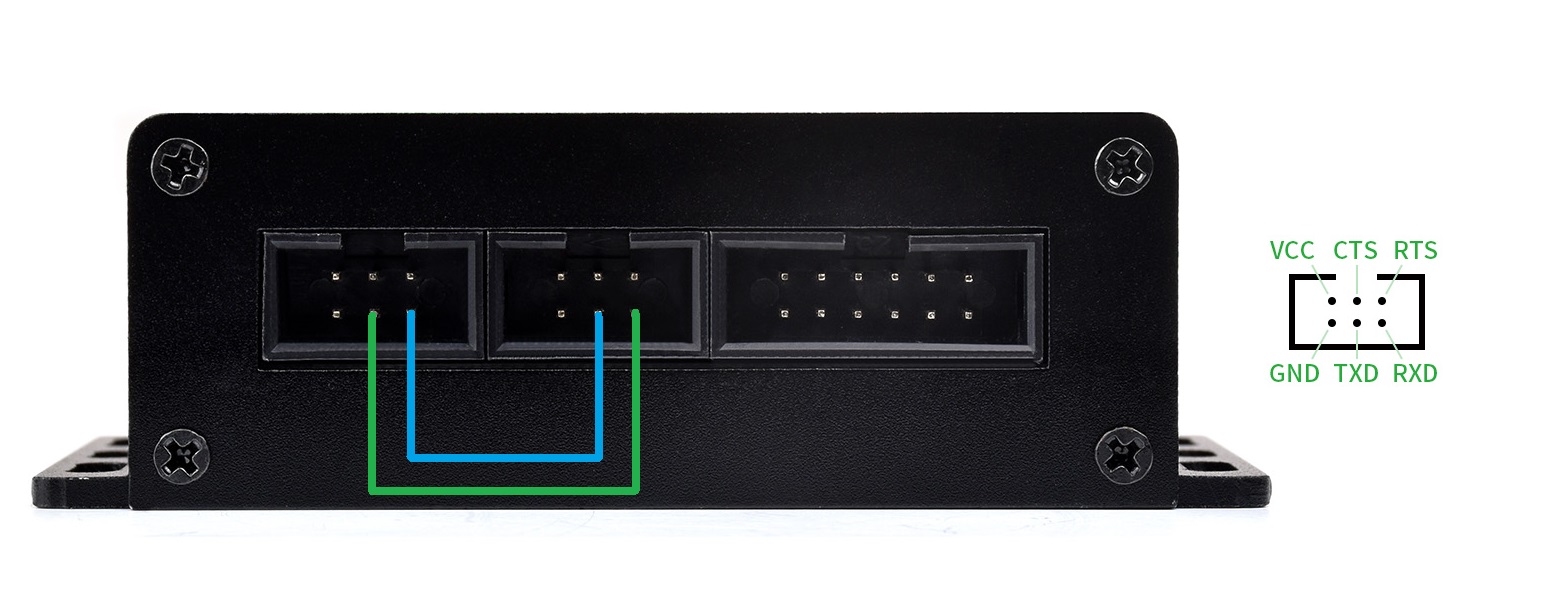
Hardware Connection
USB TO UART/I2C/SPI/JTAG(UART0) USB TO UART/I2C/SPI/JTAG(UART1) UART0.TXD UART1.RXD UART0.RXD UART1.TXD

Software Operation
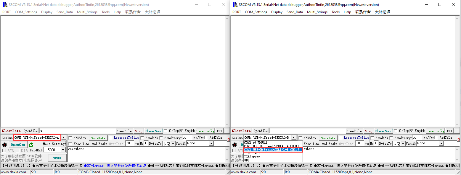
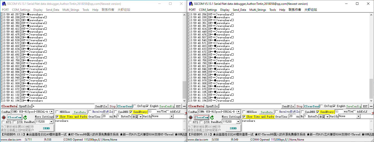
- Enable two SSCOM demos, and select two COM ports of the product.
- Set to the same baud rate, enter the characters to be sent, select "Add time stamp and packet display", and set "50ms/time, timed send".
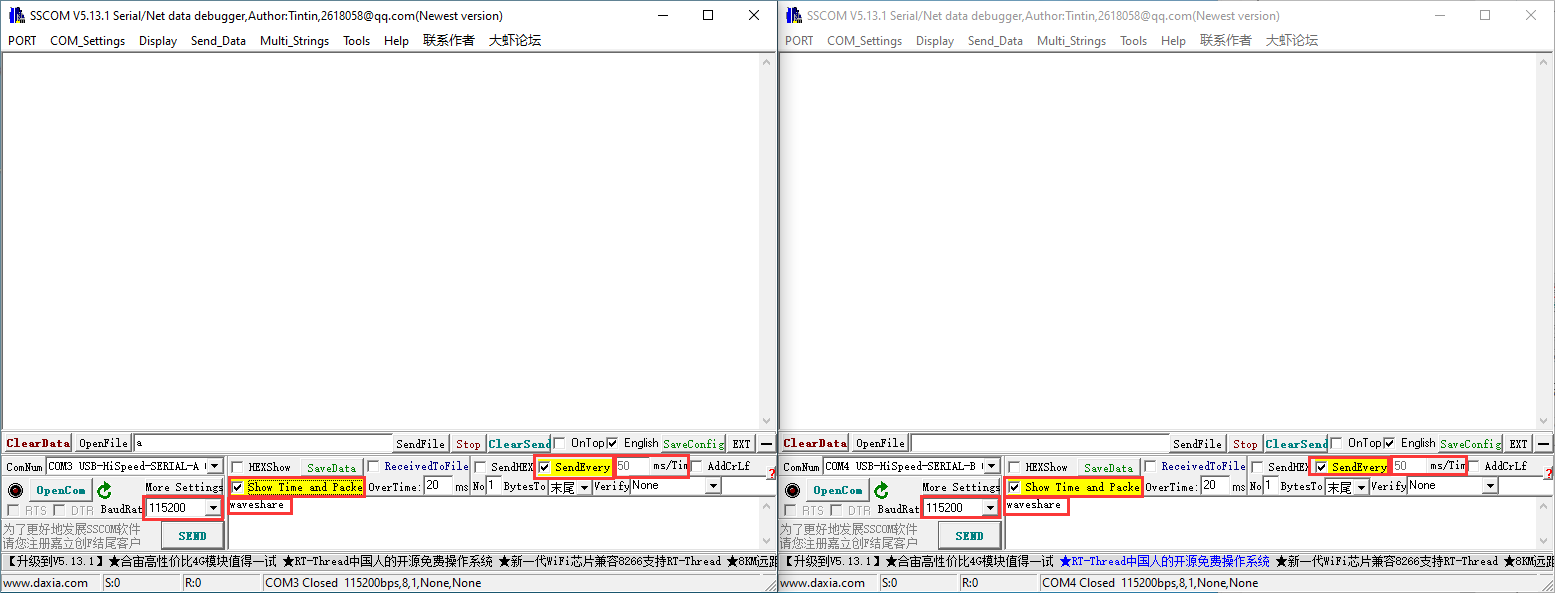
- Click on "Open Serial Ports" to receive data as shown below:
UART Self-Transmission and Reception Communication in Python IDLE
The following is a demonstration of self-sending and receiving using the product's two serial ports. (Sample demo)
Hardware Connection
USB TO UART/I2C/SPI/JTAG(UART0) USB TO UART/I2C/SPI/JTAG(UART1) UART0.TXD UART1.RXD UART0.RXD UART1.TXD

Software Operation
- Open Python IDLE, click "File -> Open..." at the top. ", go to the sample demo"... /USB-TO-UART-I2C-SPI-JTAG-Demo/Windows/Code".
- Go to the UART folder, and choose to open the UART.py file (please check if it is the corresponding port.)
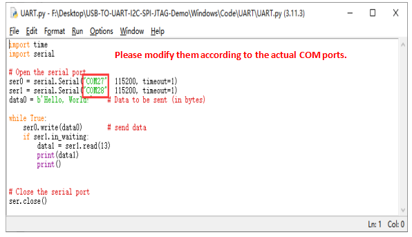
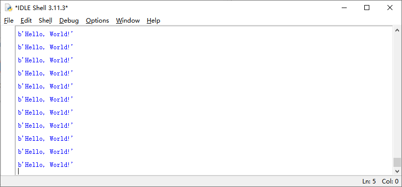
- Click "Run" -> "Run Module" or directly click F5 to run the demos.

- The effects as shown below:
How to Use I2C Interface
If you want to use the serial port debugging assistant to send and receive UART when using I2C or SPI, please switch the mode to Mode 1 (Mode 2 is HID driverless mode and will not be displayed in the port).
I2C Gets Range Measuring Module Data In Python IDE
The following is a sample demo that demonstrates how to acquire data (TF-Luna-related information and pinout) from the TF-Luna in I2C mode using the product's I2C function. (Sample demo).
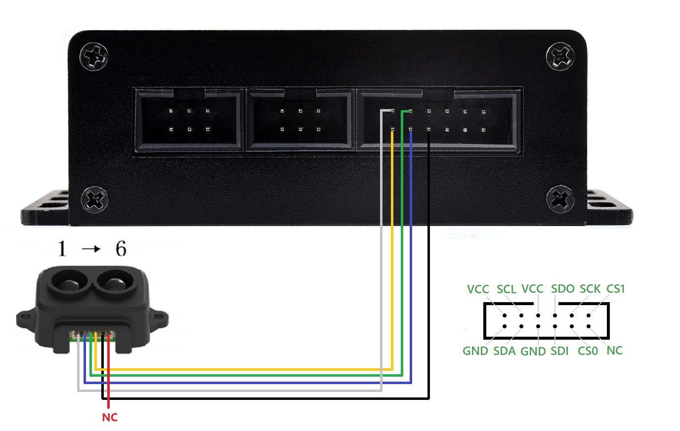
Hardware Connection
Please set the mode switch to mode 1 or mode 2 and connect the computer after connecting the cable.
Peripheral(TF-Luna) USB TO UART/I2C/SPI/JTAG Pin 1 VCC Pin 2 I2C.SDA Pin 3 I2C.SCL Pin 4 GND Pin 5 GND (Connect it first, configure TF-Luna for I2C mode (required for TF-Luna)) Pin 6 N/C
Software Operation
- Enable Python IDLE, click "File" -> Open... Enter the sample demo "../USB-TO-UART-I2C-SPI-JTAG-Demo/Windows/Code" (Sample demo).
- Enter the I2C file folder and select open I2C.py file.
① If you are using multiple USB TO UART/I2C/SPI/JTAG devices at the same time, please select the device at ① (similar to the device serial number, 0, 1, 2... etc.)
②Modify the I2C device address according to the actual need to operate.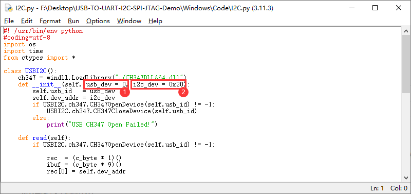
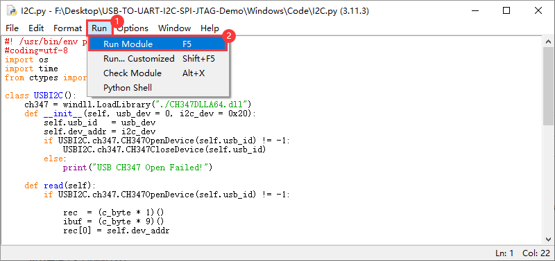
- Click "Run" -> "Run Module" or directly click F5 to run the demo.
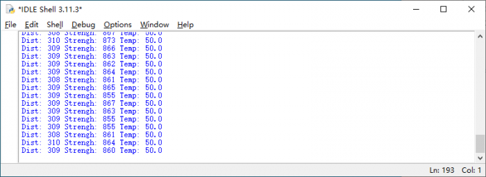
- The effects as shown below:
I2C Debug Ranging Module Using Host Computer
The following is a demonstration of using the I2C function of the product to turn on and off the data output of TF-Luna in I2C mode (TF-Luna-related information).
Download the I2C debugging software (USB TO UART_I2C_SPI_JTAG Software demo), no need to install it, directly open it to use.
Hardware Connection
Please switch the mode to mode 1 or mode 2 and connect the computer after connecting the cable.
| Peripheral(TF-Luna) | USB TO UART/I2C/SPI/JTAG |
| Pin 1 | VCC |
| Pin 2 | I2C.SDA |
| Pin 3 | I2C.SCL |
| Pin 4 | GND |
| Pin 5 | GND (Connect IT FIRST, configure TF-Luna for I2C mode (required for TF-Luna)) |
| Pin 6 | N/C |

Software Operation
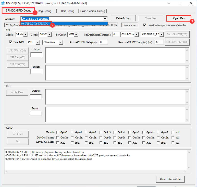
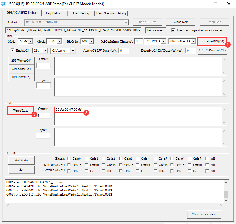
- Enable USB TO UART_I2C_SPI_JTAG Demo software to enter the I2C debugging interface, and enable the device.
- Click Initialize SPI (the software and SPI share the same interface), don't care about those parameters before the initialization button.
- Input the data to be sent in the I2C input box (the input is hexadecimal data), and click Write/Read.
20 5A 05 07 00 66
- Note that 0x20 is the I2C written address of TF-Luna.
- "0x5A 0x05 0x07 0x00 0x66" is the command to disable TF-Luna data output. (The red indicator of TF-Luna will be off.)
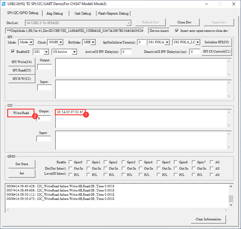
- Input 20 5A 05 07 01 67, clicking Write/Read will turn on the TF-Luna's data output (the TF-Luna's red light is on again).
20 5A 05 07 01 67
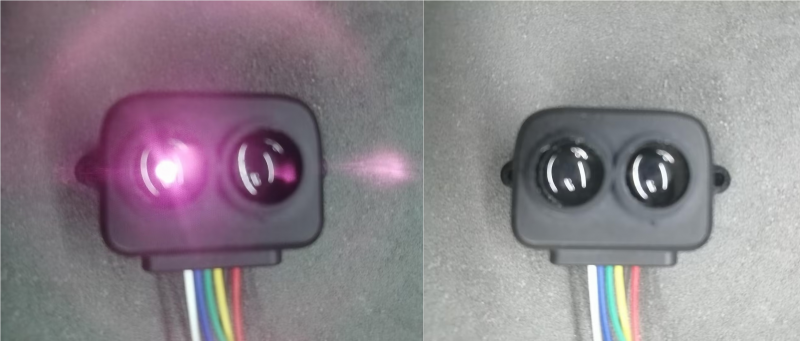
- The phenomenon is as follows (the shooting effect is more conspicuous than the human eye observation, please turn the TF-Luna to prevent the angle from not observing it).
SPI Interface Usage Demo
If you want to use the serial port debugging assistant to send and receive UART when using I2C or SPI, please switch the mode to Mode 1 (Mode 2 is HID driverless mode and will not be displayed in the port).
SPI Drives OLED Screen In Python IDLE
The following is a demonstration of using the product's SPI function to turn on an OLED in SPI mode (OLED-related information) (sample demo)
Environmet Debugging Description
The current example has already been set up, so there is no need to do the following operation:
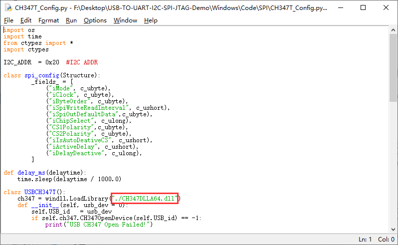
The DLL file should be placed in the directory where the demo program is located, there are two DLL files stored in the sample file (corresponding to 64-bit system and 32-bit system respectively), please adjust according to the system. 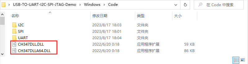
- Or you can modify the file path in the demo as the DLL file storage path.
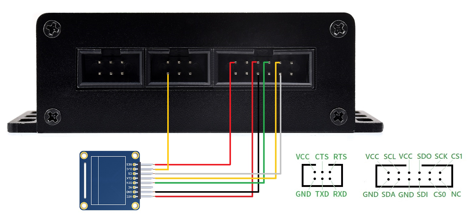
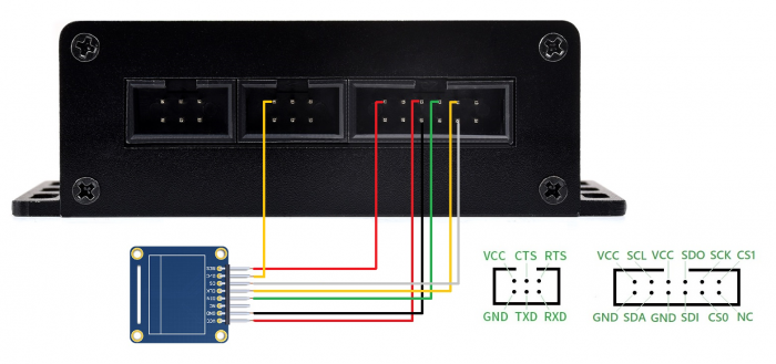
Hardware Connection
Please set the mode switch to mode 1 or mode 2 and connect the computer after connecting the cable.
| Peripheral | USB TO UART/I2C/SPI/JTAG |
| RES | UART1.RTS (Used to control OLEDs for reset (required for OLEDs)) |
| D/C | UART1.CTS (Used to indicate whether a command or data is being sent (required for OLEDs)) |
| CS | SPI.CS0 |
| CLK | SPI.SCK |
| DIN | SPI.SDO |
| GND | SPI.GND |
| VCC | SPI.VCC |

Software Operation
- Open Python IDLE, click "File -> Open..." at the top. ", go to the sample demo "... /USB-TO-UART-I2C-SPI-JTAG-Demo/Windows/Code" (example demo).
- Go to the SPI folder, and choose to open the example.py file.
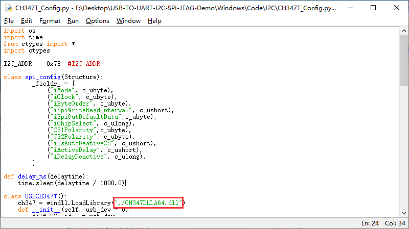
① If you are using more than one USB TO UART/I2C/SPI/JTAG device at the same time, please select the device at ① in the CH347T_Config.py file (similar to the device serial number, 0, 1, 2... etc.)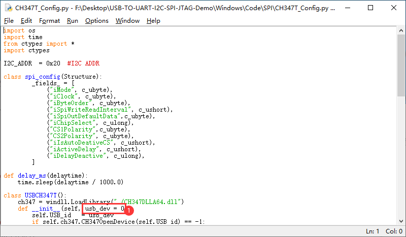
- Click "Run" -> "Run Module" or click F5 to run the demo.
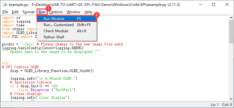
- The effect is shown below:

SPI Debug OLED Screen Using Host Computer
The following is a demonstration of using the SPI function of the product to light up the OLED in SPI mode (OLED-related information) Download the SPI debugging software (USB TO UART_I2C_SPI_JTAG Software demo), no need to install, and directly open the use.
Hardware Connection
Please set the mode switch to mode 1 or mode 2 and connect the computer after connecting the cable.
| Peripheral | USB TO UART/I2C/SPI/JTAG |
| RES | I2C.VCC ((Keeping the OLED in operation (required for OLED)) |
| D/C | URAT0.GND (Used to indicate whether a command or data is being sent (required for OLEDs)) |
| CS | SPI.CS0 |
| CLK | SPI.SCK |
| DIN | SPI.SDO |
| GND | SPI.GND |
| VCC | SPI.VCC |
Software Operation
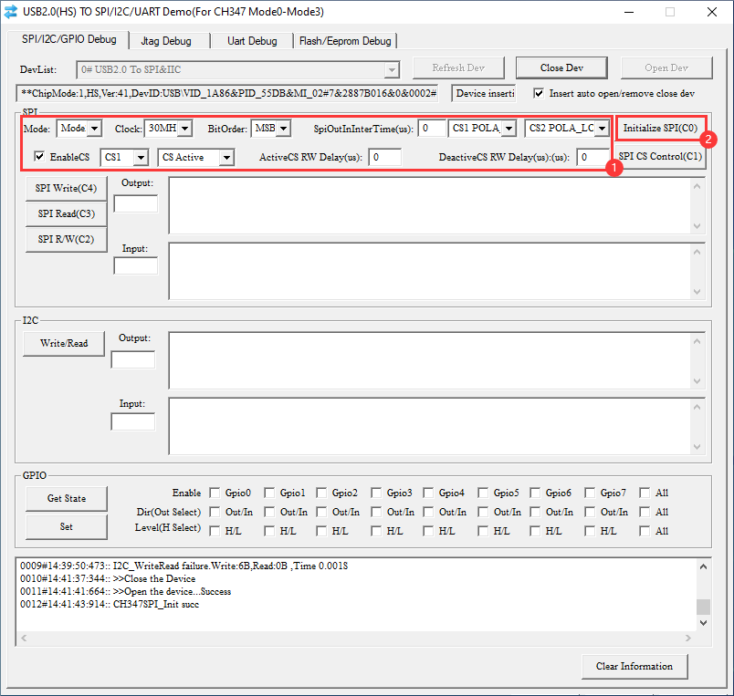
- Enable USB TO UART_I2C_SPI_JTAG Demo software to enter the SPI debugging interface, and enable the device.

- Initialize SPI parameters according to the use of the environment, after selecting the parameters click on the initialization of SPI (more clicks on the initialization of SPI, to prevent initialization failure).
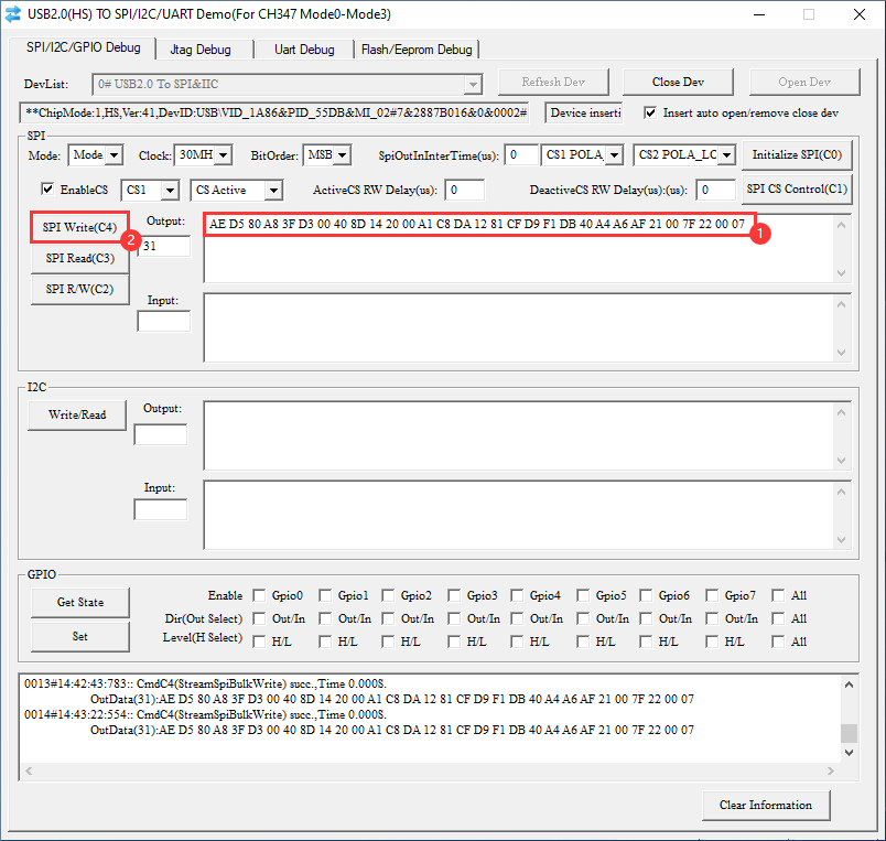
- Enter the data to be sent in the SPI input box and select SPI Read, SPI Write or SPI Read/Write according to the desired operation.
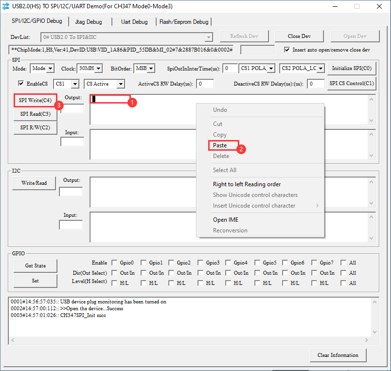
- The data below are OLED initialization commands (use the right mouse button to paste the data, keyboard shortcuts cannot be used):
AE D5 80 A8 3F D3 00 40 8D 14 20 00 A1 C8 DA 12 81 CF D9 F1 DB 40 A4 A6 AF 21 00 7F 22 00 07
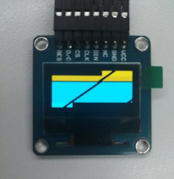
- Initialization effect as shown below: (the screen is not on).
- Connect the D/C pin of the OLED to VCC (Connecting to GND for sending commands, to VCC for sending data):
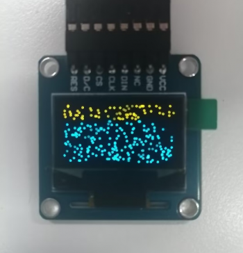
- Sending data to clear the screen (use the right mouse button to paste the data, keyboard shortcuts cannot be used), click SPI once and clear part of them:
00 00 00 00 00 00 00 00 00 00 00 00 00 00 00 00 00 00 00 00 00 00 00 00 00 00 00 00 00 00 00 00 00 00 00 00 00 00 00 00 00 00 00 00 00 00 00 00 00 00 00 00 00 00 00 00 00 00 00 00 00 00 00 00 00 00 00 00 00 00 00 00 00 00 00 00 00 00 00 00 00 00 00 00 00 00 00 00 00 00 00 00 00 00 00 00 00 00 00 00 00 00 00 00 00 00 00 00 00 00 00 00 00 00 00 00 00 00 00 00 00 00 00 00 00 00 00 00 00 00 00 00 00 00 00 00 00 00
- Sending data to light on (use the right mouse button to paste the data, keyboard shortcuts cannot be used), click SPI once and clear part of them:
FF FF FF FF FF FF FF FF FF FF FF FF FF FF FF FF FF FF FF FF FF FF FF FF FF FF FF FF FF FF FF FF FF FF FF FF FF FF FF FF FF FF FF FF FF FF FF FF FF FF FF FF FF FF FF FF FF FF FF FF FF FF FF FF FF FF FF FF FF FF FF FF FF FF FF FF FF FF FF FF FF FF FF FF FF FF FF FF FF FF
JTAG Interface Usage
STM32 Microcontroller Debugging And Burning On OpenOCD
The following is a demonstration of burning a demo into the STM32F429IGT6 development board using the product's JTAG interface.
Please note: Make sure the device is at 3V3 and not 5V (keep the same potential as the device to be burned).
Hardware Connection
External JTAG Interface USB TO UART/I2C/SPI/JTAG TDI TDI TDO TDO TMS TMS TCLK TCK TRST (N/C) TRST (N/C) GND GND
Preparation
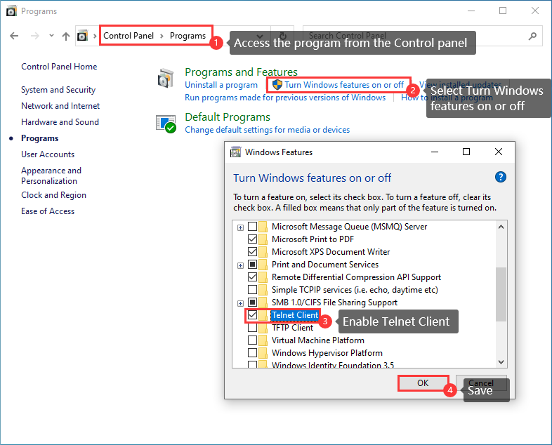
- Enable Telnet Function.
- Click the Win+R key, and input "cmd" to enter the command window.
- Go to the "USB-TO-UART-I2C-SPI-JTAG-Demo\Windows\Software\OpenOCD-CH347\bin" directory in the path of the package (the demo is for the desktop).
cd Desktop\USB-TO-UART-I2C-SPI-JTAG-Demo\Windows\Software\OpenOCD-CH347\bin

- Connect CH347 and STM32F4 (openocd.exe -f ch347.cfg -f + parameter: here the parameter is the configuration file of the connected chip, you can copy the file to the bin folder in the 2nd point, otherwise you need to add the path of the configuration file.)
Note: The configuration file of the common chip is stored in "USB-TO-UART-I2C-SPI-JTAG-Demo\Windows\Software\OpenOCD-CH347\scripts\target", you can copy the file to the current folder.
openocd.exe -f ch347.cfg -f stm32f4x.cfg
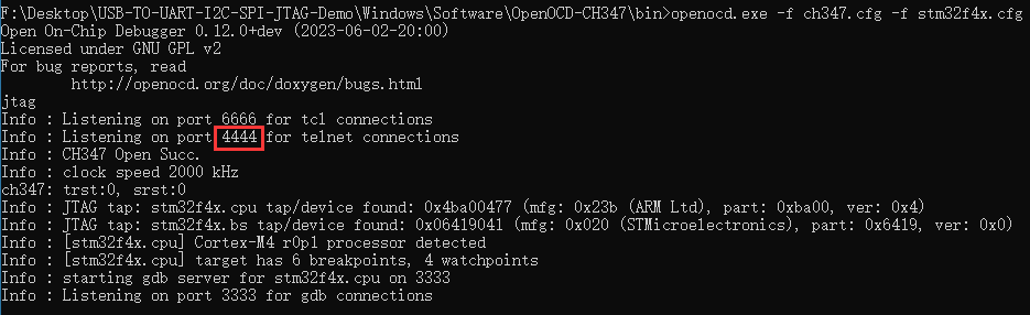
- Click "Win +R" to enable the new command window.
- telnet.exe Localhost 4444 (Return the result according to the above)
telnet.exe Localhost 4444

- If the following characters show, the connection is successful:

- Program the demo to STM 32F4 using Openocd.
Demo Download
- Copy the hex file to the directory "USB-TO-UART-I2C-SPI-JTAG-Demo\Windows\Software\OpenOCD-CH347\bin".
Note: In the example file, there is a Test folder under the bin file, and there are two files under the folder that correspond to the clockwise and counterclockwise control of the light source by pressing the key under the Open429I-C (Package A).
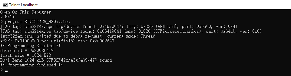
- Enter "halt" in the Telnet window to pause the running demo.
halt
- Execute "program STM32F429_439xx.hex" to download the program (program + parameter: here the parameter is the hex file to be downloaded, you can copy it to the bin folder mentioned in the previous operation, or you need to change the parameter to path + hex file or elf file to be downloaded).
- Please note: Do not name files with spaces!
program STM32F429_439xx.hex
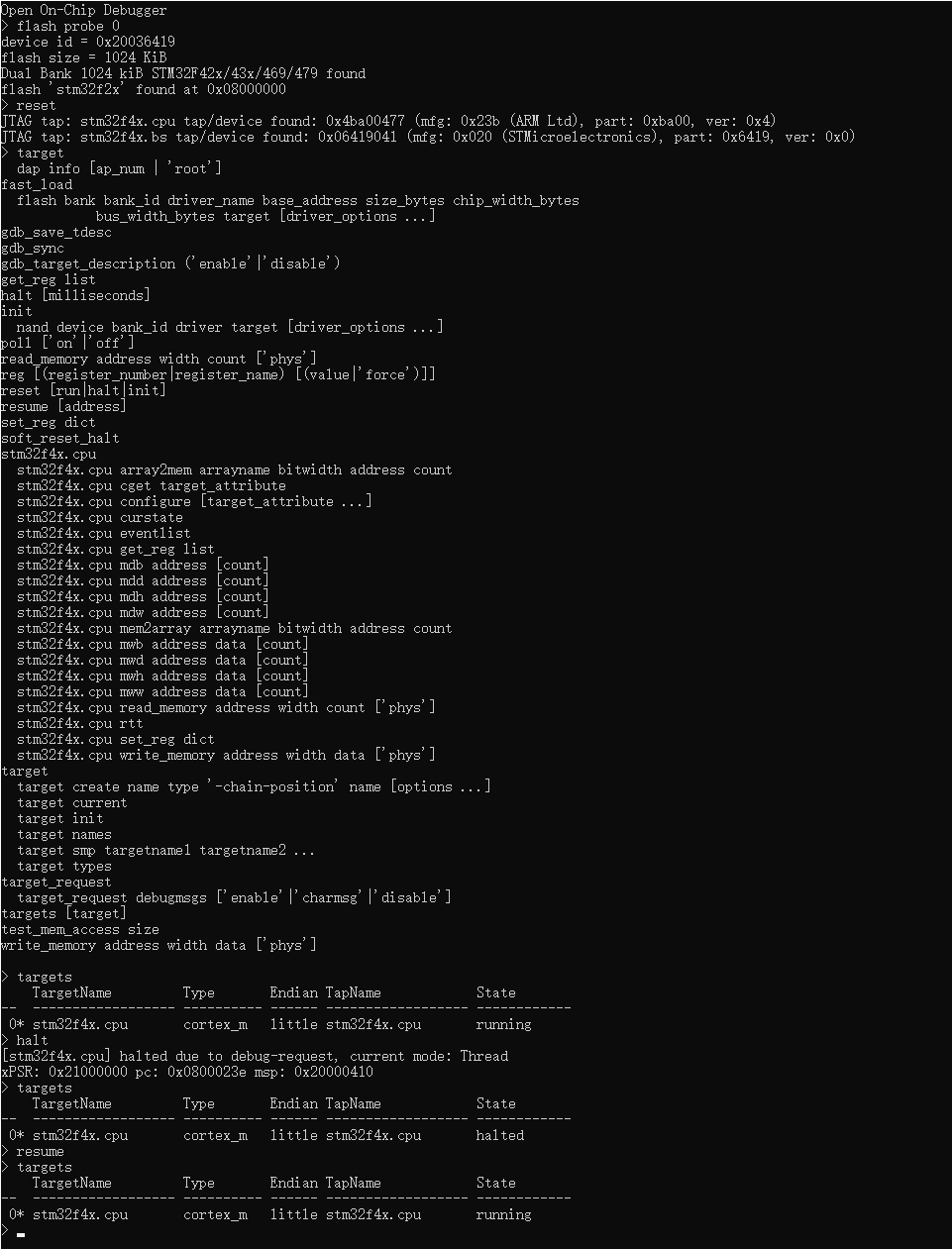
Demo Debug
- The debugging command "halt" has already been used in the program download to pause the running program.
- Use "flash probe 0" to scan the flash.
- Execute various debugging commands for functional debugging (e.g. reset, halt, resume, etc.).
Porting Description
Porting Reference
Environment Configuration Instructions
- DLL files should be placed in the directory where the demo program is located. There are two DLL files in the sample files (corresponding to 64-bit and 32-bit systems respectively). Please adjust it according to your system.

- Or you can modify the file path of the demo as a DLL file storage path.
Example Reference
Note: The demo is modified based on the Raspberry Pi driver OLED demo.
Reference link: OLED related resource Reference example is the file under "../OLED_Module_Code /RaspberryPi/python". (Sample demo)
- The I2C and SPI examples is in "../USB-TO-UART-I2C-SPI-JTAG-Demo/Windows/Code"
- Application 1: Use the I2C port of the product to turn on OLED. (device used: 0.96inch OLED (A))
- Application 2: Use the SPI port of the product to turn on OLED. (device used: 0.96inch OLED (A))
File Description
- CH347T_Config.py corresponds to the reference example "../OLED_Module_Code/RaspberryPi/python/lib/waveshare_OLED/config.py", define CH347T device initialization, etc.
- OLED_Library_Function.py corresponds to the reference example "../OLED_Module_Code/RaspberryPi/python/lib/waveshare_OLED/OLED_0in96.py", define OLED device initialization, etc.
- example.py corresponds to the reference example "../OLED_Module_Code/RaspberryPi/python/lib/waveshare_OLED/OLED_0in96_test.py", and is the mainstream program.
- The pic folder storages images and font files.
Linux (Raspberry Pi)
Environment Setting
Driver Installation
Download the file package to the Raspberry Pi and unzip the file:
wget https://files.waveshare.com/wiki/USB-TO-UART-I2C-SPI-JTAG/USB-TO-UART-I2C-SPI-JTAG-Demo.zip
unzip USB-TO-UART-I2C-SPI-JTAG-Demo.zip -d ./USB-TO-UART-I2C-SPI-JTAG-Demo
Execute example: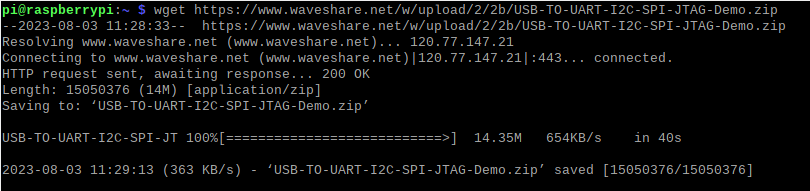
Enter the driver file directory:
cd USB-TO-UART-I2C-SPI-JTAG-Demo/Raspberry/Driver/driver/
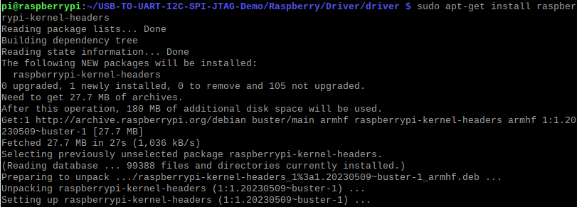
Install the execution environment on Raspberry Pi:
sudo apt-get install raspberrypi-kernel-headers
Install on Ubuntu with different commands:
sudo apt-get update
sudo apt-get install build-essential
sudo apt install python3-pip
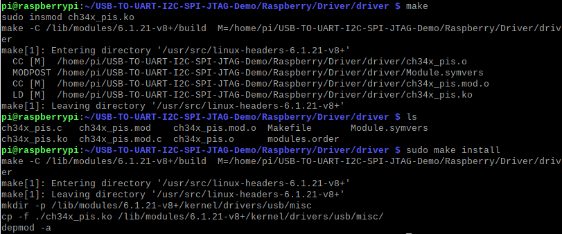
Execute compilation and load the driver:
make
sudo insmod ch34x_pis.ko
Use the driver demo to operate permanently:
sudo make install
- Install serial library: (If you fail, you can execute sudo pip3 install pyserial)
pip install pyserial
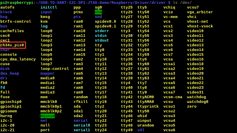
- Switch to Mode1 and connect to the Raspberry Pi, view the device, and see "ch34x_pis*".
ch34x_pis*"
- The devices identified by different modes:
Mode Device number Mode 0 tty* and tty* (often ttyACM*) Mode 1 ch34x_pis* and tty* Mode 2 hidraw* Mode 3 ch34x_pis* and tty*
Preparation
- View the system information:
uname - a
- armv61 (32-bit)
- armv71 (32-bit)
- aarch64 (64-bit)
- x86_64 (64-bit but not Raspberry Pi)
If the return value is armv61 or armv71, it means it is 32-bit ARM architecture (for Raspberry Pi). If the return value is aarch64, it means it is 64-bit ARM architecture (for Raspberry Pi). If the return value is x86_64, it is not Raspberry Pi. Select x64 folder.
Currently using the Raspberry Pi 64-bit libraries, if your query result is aarch64, then you do not need to do the following operations.
- Enter the downloaded file, "../USB-TO-UART-I2C-SPI-JTAG-Demo/Raspberry/Code/lib/XXX" (XXX: select the file folder according to the above query result).
cd
cd USB-TO-UART-I2C-SPI-JTAG-Demo/Raspberry/Lib/aarch64

- Copy the files with the ".so" extension to the program folder. If there is already a ".so" file in the folder that is intended for use on aarch64 architecture, replace it with the ".so" file that is compatible with your current system.
For instance, copy the appropriate ".so" file into the I2C example:
sudo cp libch347.so ../../Code/I2C/

- Or copy to SPI example:
sudo cp libch347.so ../../Code/SPI/
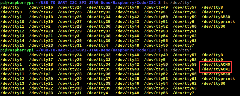
- When using UART, it is the same as other normal UART devices (the device number identified by the Raspberry is ttyACM*, and the new devices can be queried by plugging and unplugging devices.)
1. Do not connect USB TO UART/I2C/SPI/JTAG first, use the commands to query the current device:
ls /dev/tty*
2. Connect the Raspberry Pi and USB TO UART/I2C/SPI/JTAG, and query "ls /dev/tty*", the new device is the device number of the product:
ls /dev/tty*

UART Interface Usage
The following is a demonstration of using the product's two serial ports for self-sending and receiving, please switch the mode to mode 0 (for two tty* devices).
Serial Self-sending and Receiving Communication in Python Environment
Hardware Connection
USB TO UART/I2C/SPI/JTAG(UART0) USB TO UART/I2C/SPI/JTAG(UART1) UART0.TXD UART1.RXD UART0.RXD UART1.TXD
Software Operation
- Query the current identified device number:
1. Do not connect USB TO UART/I2C/SPI/JTAG first, and use commands to query the current device.
ls /dev/tty*
2. Connect the Raspberry Pi and USB TO UART/I2C/SPI/JTAG, query "ls /dev/tty*" again, and the new device is the device number of the product.
ls /dev/tty*

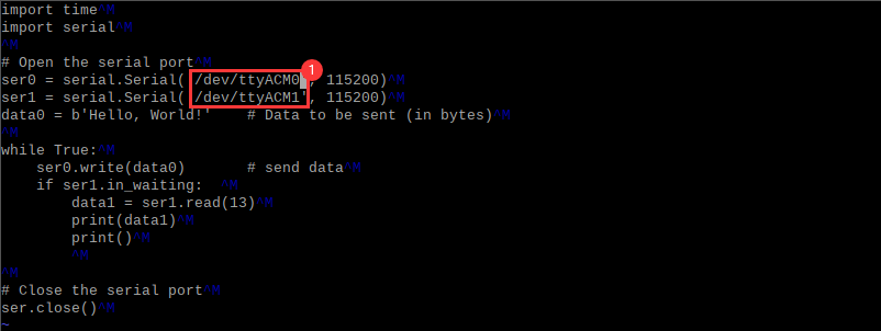
- Enter the UART example directory, and edit the program UART.py.
cd USB-TO-UART-I2C-SPI-JTAG-Demo/Raspberry/Code/UART/
vi UART.py

- Move the cursor to position ① and change it to the recognized device number (move the cursor using 'up, down, left and right keys' -> click 'i' and then modify it -> click 'Esc' after modifying it -> input ':wq' to save and exit).
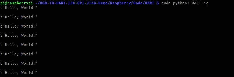
- Execute demo:
sudo python3 UART.py
I2C Interface Usage
If you want to use the UART to send and receive data when using I2C or SPI, switch the mode to mode 1 or mode 2 (mode 1 for ch34x_pis* and tty* devices, mode 2 for hidraw* devices).
I2C Gets Ranging Module Data in Python Environment
Hardware Connection
Please switch to Mode 1 or Mode 2, and connect to the computer by connecting the cables.
Peripheral(TF-Luna) USB TO UART/I2C/SPI/JTAG Pin 1 VCC Pin 2 I2C.SDA Pin 3 I2C.SCL Pin 4 GND Pin 5 GND (Connect first and configure TF-Luna to I2C mode (required for TF-Luna)) Pin 6 N/C

Software Operation
- Query the current identified device number (connect the Raspberry Pi and USB TO UART/I2C/SPI/JTAG, query the device).
Mode 1 Query 'ch34x_pis*' and 'tty*', can be queried once when the device is connected and once when the device is not connected(('ch34x_pis*' for SPI/I2C,'tty*' for UART)).
ls /dev/ch34x_pis*

Mode 2 Query 'hidraw*', can be queried once when the device is connected and once when the device is not connected.
ls /dev/hidraw*

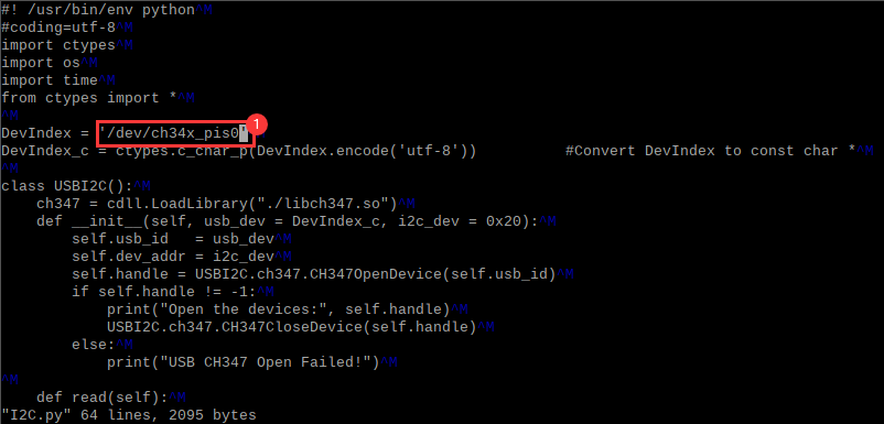
- Enter the I2C example directory, and edit the demo I2C.py:
cd USB-TO-UART-I2C-SPI-JTAG-Demo/Raspberry/Code/I2C/
vi I2C.py

- Move the cursor to position ① and change it to the recognized device number (move the cursor using 'up, down, left and right keys' -> click 'i' and then modify it -> click 'Esc' after modifying it -> input ':wq' to save and exit).
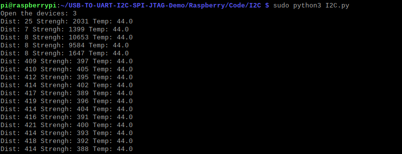
- Execute the demo:
sudo python3 I2C.py
SPI Interface Usage
If you want to use I2C or SPI to transmit the data by UART, you can switch to mode 1 or mode 2.
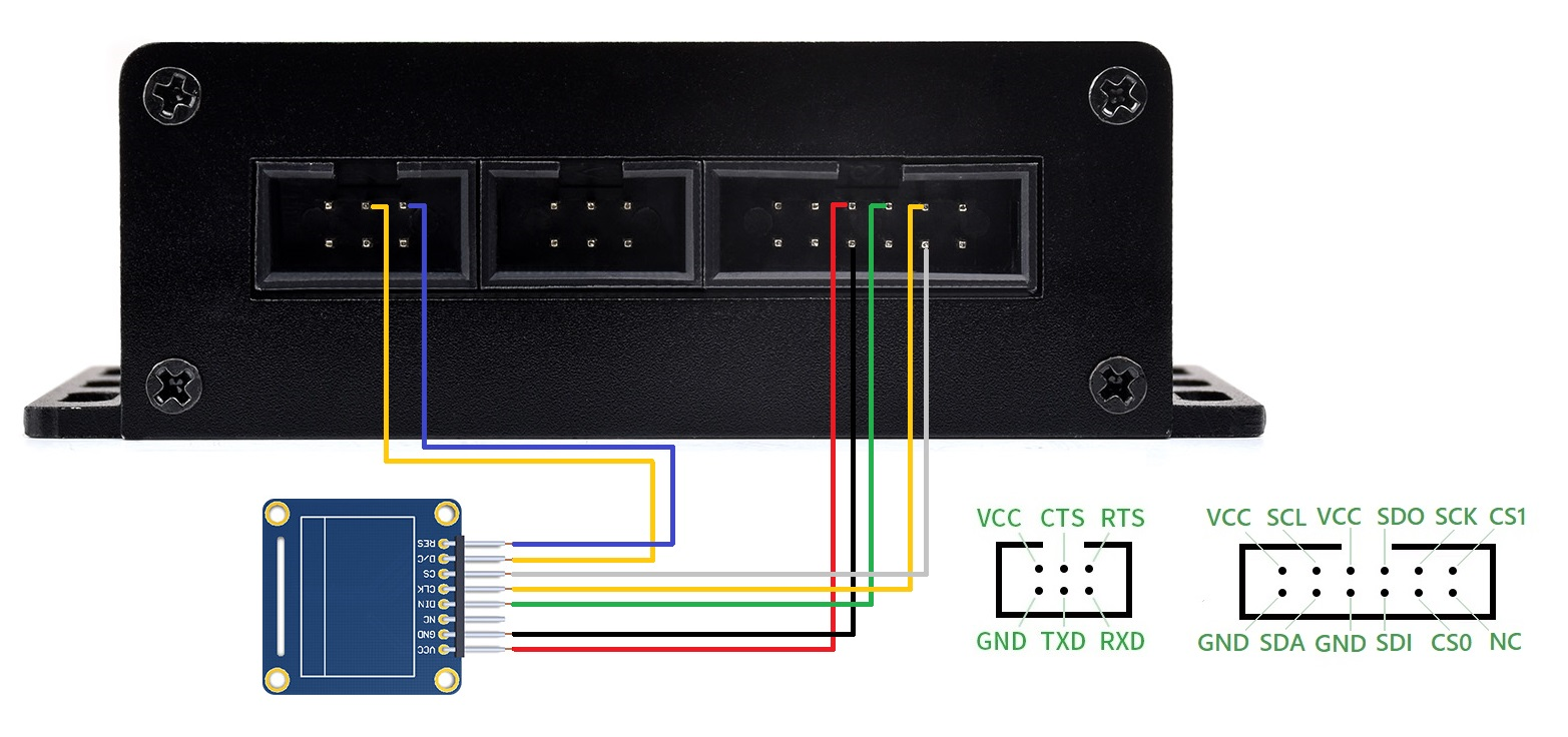
SPI Drives OLED Screen In Python Environment
Hardware Connection
Please set the mode switch to mode 1 or mode 2 and connect the computer after connecting the cable..
Peripheral USB TO UART/I2C/SPI/JTAG RES UART1.RTS (Used to control OLEDs for reset (required for OLEDs)) D/C UART1.CTS (Used to indicate whether a command or data is being sent (required for OLEDs)) CS SPI.CS0 CLK SPI.SCK DIN SPI.SDO GND SPI.GND VCC SPI.VCC
Software Operation
- Query the current identified device number (connect the Raspberry Pi and USB TO UART/I2C/SPI/JTAG, query the device).
Mode 1 Query 'ch34x_pis*' and 'tty*' once for both connected and unconnected devices ('ch34x_pis*' for SPI/I2C,'tty*' for UART).
ls /dev/ch34x_pis*
Mode 2 Query 'hidraw*' once for both connected and unconnected devices.
ls /dev/hidraw*

- Enter the SPI example directory, and edit the demo CH347T_Config.py.
cd USB-TO-UART-I2C-SPI-JTAG-Demo/Raspberry/Code/SPI/
vi CH347T_Config.py

- Move the cursor to position ① and change it to the recognized device number (move the cursor using 'up, down, left and right keys' -> click 'i' and then modify it -> click 'Esc' after modifying it -> input ':wq' to save and exit).

- Execute the demo:
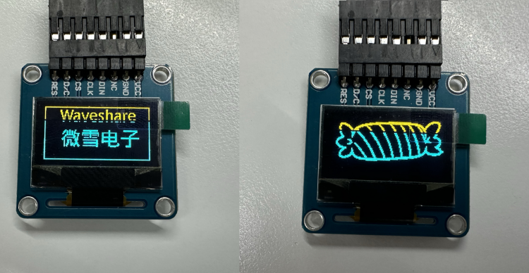
sudo python3 example.py
- The effects as shown below:
Resource
Demo and Materials
Software and Driver
FAQ
Question:Mode switching has no effect?
This may be the case of switching modes after not carrying out the power-off operation:
1. First disconnect the device from the computer.
2. Toggle the mode switch to adjust to the desired mode.
3. Reconnect the device with the computer.
Question:Temperature data is -255 or distance data is 65535 when using the I2C debugging example?
In this case, the TF-Luna (external device) may not be configured to I2C mode.
1. Disconnect all the wires between TF-Luna and the device.
2. Connect the fifth wire of TF-Luna first, and then connect the other wires in turn.
Question:Unstable sending and receiving of data during communication?
- 1: It may be caused by the mismatch between the device communicating with this product and the current communication level of the device.
- 1. Please check whether the allowable level of the equipment communicating with this product is 3.3V or 5V.
- 2. Toggle the level switch to adjust the communication level to be consistent with the external equipment.
- 1. Please check whether the allowable level of the equipment communicating with this product is 3.3V or 5V.
- 2: It may be caused by the high power consumption of the device communicating with this product or more devices using the VCC port of this product for power supply.
- 1. Please use an external power supply for the device connected to the product and connect the GND of the power supply device to the GND of the product.
- 2. Please note that the GND of each device needs to be connected together.
- 1. Please use an external power supply for the device connected to the product and connect the GND of the power supply device to the GND of the product.
Question:The example runs with a missing PIL library as follows:
![]()
- Click WIN + R, and execute the following PIL installation commands:
pip install pillow
- If it can not be downloaded normally, you can use other sources to download:
pip install -i https://pypi.tuna.tsinghua.edu.cn/simple pillow
Question:How to read I2C data using USB TO UART/I2C/SPI/JTAG?
- Please enter the device address + register address in the I2C output box as follows:

- A0 indicates the address after the device address is shifted to the left by 1 bit (the read/write bit will be handled automatically, just offset the device address by one bit), 00 00 indicates the address of the register to be read.
- If the register address is 16 bits, send the low byte first (according to the requirements of the slave device, some devices need to send the high byte first), such as reading the 10 bytes of the 0x0004 address (the input length position needs to be filled in the number of bytes to be read):

- Please note that if the slave device has other corresponding operations for data acquisition, please make adjustments according to the specific operations of the slave device.
Question:3V3 communication succeeds while 5V communication fails?
Please check whether the communication device supports 5V.
Support
[Tutorial Navigation]
- Overview
- Windows
- Environment Building
- UART Interface Usage Demo
- UART Self-Transmission and Reception Communication in SSCOM
- UART Self-Transmission and Reception Communication in Python IDLE
- How to Use I2C Interface
- SPI Interface Usage Demo
- JTAG Interface Usage
- Porting Description
- Linux (Raspberry Pi)
- Environment Setting
- Preparation
- UART Interface Usage
- I2C Interface Usage
- SPI Interface Usage
- Resource
- FAQ
- Question:Mode switching has no effect?
- Question:Temperature data is -255 or distance data is 65535 when using the I2C debugging example?
- Question:Unstable sending and receiving of data during communication?
- Question:The example runs with a missing PIL library as follows:
- Question:How to read I2C data using USB TO UART/I2C/SPI/JTAG?
- Question:3V3 communication succeeds while 5V communication fails?
- Support