- sales/support
Google Chat:---
- sales
+86-0755-88291180
- sales01
sales@spotpear.com
- sales02
dragon_manager@163.com
- support
tech-support@spotpear.com
- CEO-Complaints
zhoujie@spotpear.com
- Only Tech-Support
WhatsApp:13246739196
- Purchase/Shipping/Refund
WhatsApp:13424403025
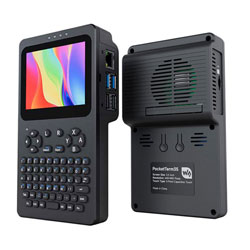
PocketTerm35-Pi4 User Guide
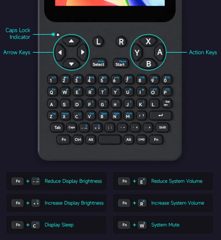
Interface Description
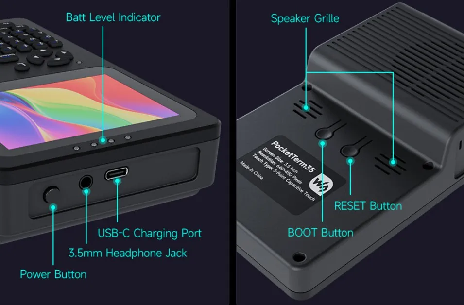
Button Description
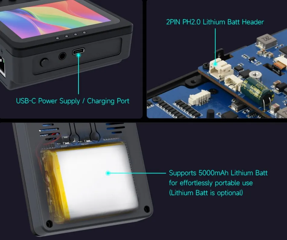
Internal Interface Description
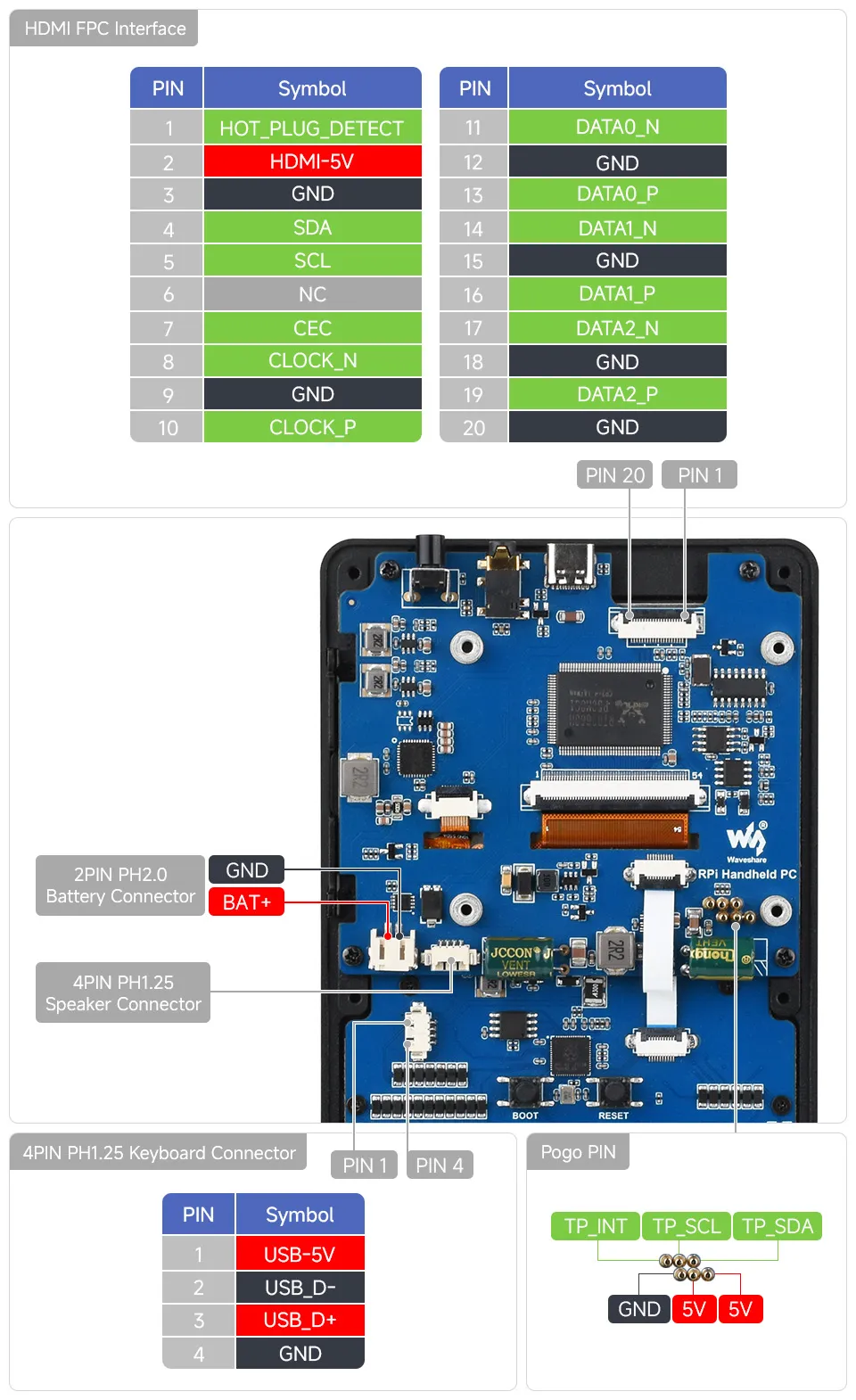
Internal Space Description
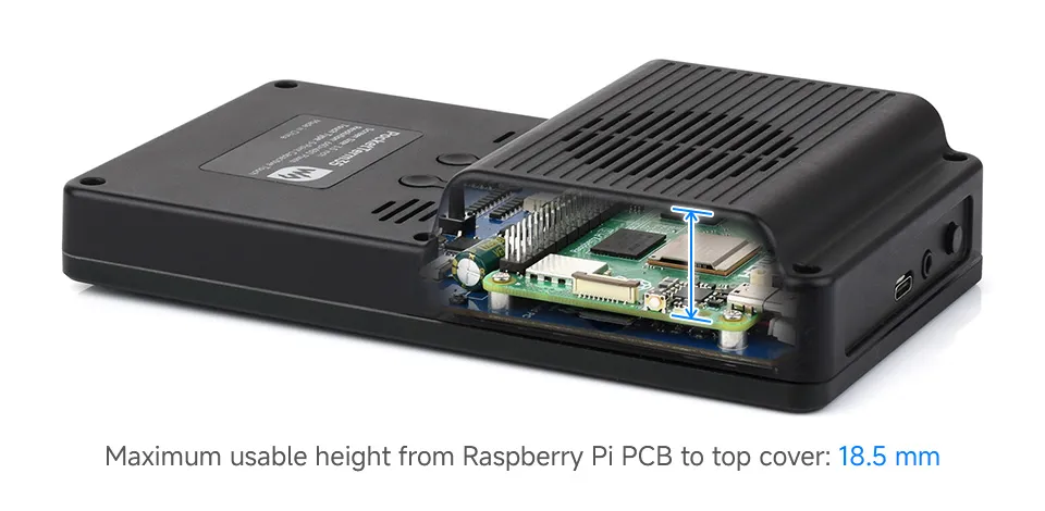
The space above the Raspberry Pi main board is quite limited. The height of any add-on board must be within 2.5 mm above the tallest component on the Raspberry Pi.
M.2 Storage Expansion Solution
To use M.2 storage, it is recommended to use the PCIe TO M.2 Board (E).
This solution is only compatible with PocketTerm35 units equipped with a Raspberry Pi 5. It enables M.2 SSD expansion via the Raspberry Pi 5's PCIe interface while taking structural space and thermal design into account.
Although other SSD solutions may be dimensionally compatible, they generally cannot accommodate a fan at the same time. It is not recommended to use other SSD solutions with this product’s structure.
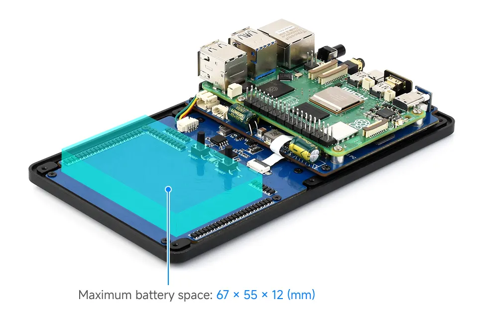
Battery Space
A battery with dimensions of 67 × 55 × 12 mm is recommended. This is the best fit for the current structure, ensuring installation stability.
Other batteries with similar dimensions that respect the internal space constraints may also be used, provided they do not interfere with structural components or internal component layout.
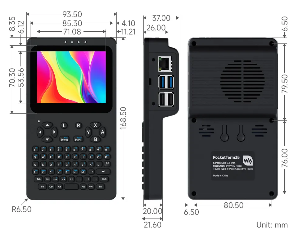
Dimensions
Assembly Guide
Pre-Assembled Version Notes
If you purchased the PocketTerm35-Pi4 or PocketTerm35-Pi5 pre-assembled version, the device comes fully assembled with the system pre-installed. No assembly steps are required below.
Simply press the top power button to power on and start using it. Default login credentials:
- Username:
pi - Password:
raspberry
Assembly Preparation
Please check the accessories list to ensure everything is complete before starting assembly.
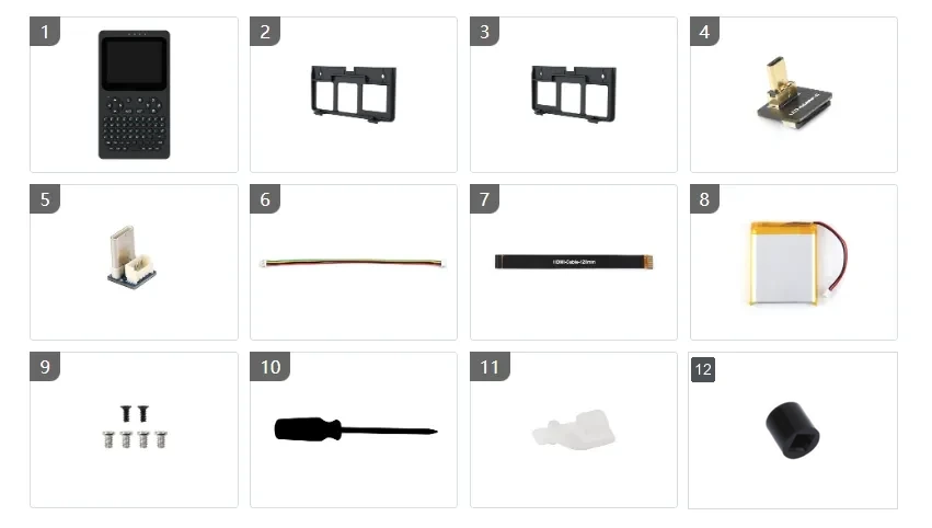
Assembly Steps
- If a side panel is already installed, remove it first.
- Before disassembly or assembly, remove the TF card to avoid damaging the card or the slot.
- Upon receiving the product, please first check the appearance of the battery. If you find swelling, damage, leakage, or any other abnormality, do not power on the device and contact after-sales support promptly.
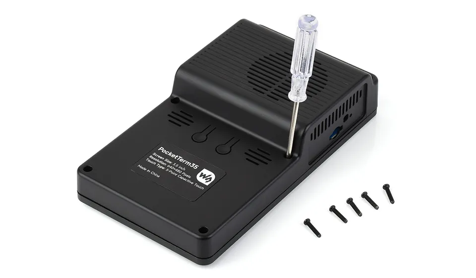
Step 1: Remove the Back Cover
Unscrew the 6 PM2.5×12 black screws, then lift the back cover upward from the bottom and remove it.
When removing the back cover, do not pull forcibly to avoid damaging internal cables or connectors.
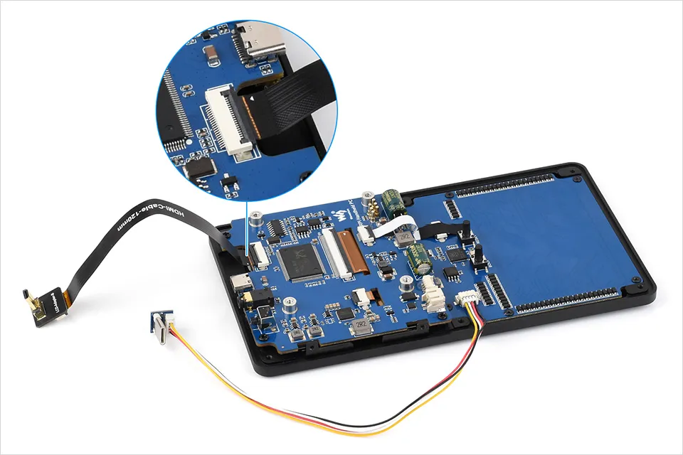
Step 2: Assemble the Cables
Use accessories ④⑤⑥⑦ to assemble the Micro HDMI cable and USB Type-C cable as shown below.
- Before inserting the FPC ribbon cable, make sure the gold contacts are facing the correct direction.
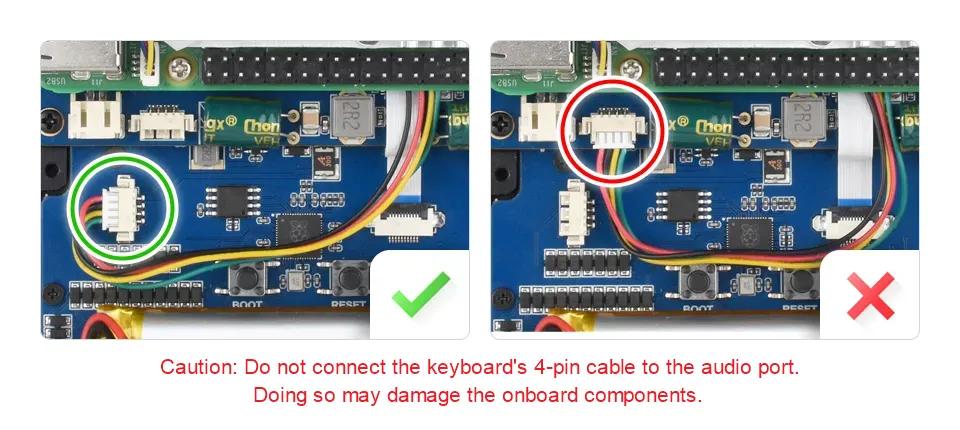
- Do not connect the keyboard 4PIN cable to the audio interface, as this may damage the device.
Step 3: Secure the Raspberry Pi
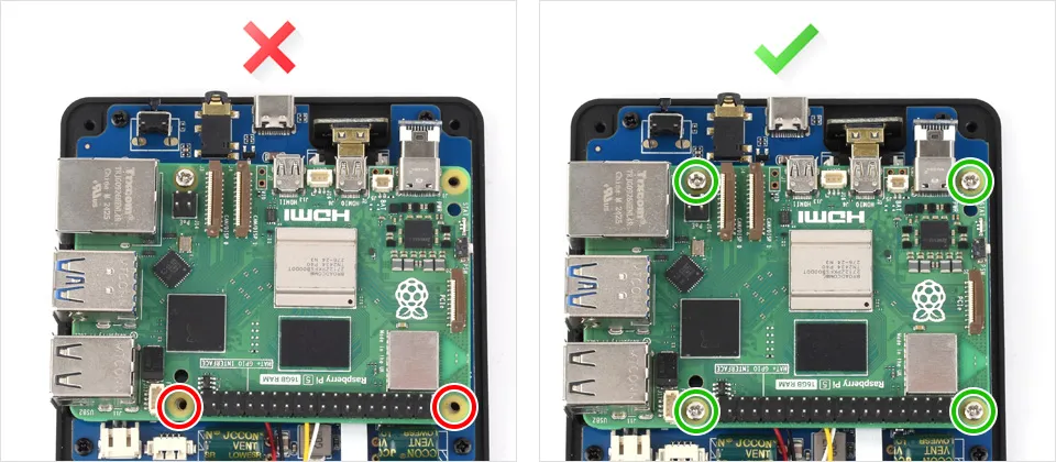
Before securing the Raspberry Pi, ensure the main board is aligned with the brass standoffs to guarantee good pogo-pin contact and avoid misalignment or uneven stress.
Use the 4 PM2.5*4 round-head screws from accessory ⑨ to secure the Raspberry Pi to the PCBA.
Step 4: Connect the Battery (Optional)
If you purchased the version without a battery, skip this step.
Make sure the Raspberry Pi board is correctly installed before connecting the battery to avoid short circuits due to incorrect connection.
Connect the 5000mAh lithium battery (accessory ⑧) to the PH2.0 connector and secure the battery position with double-sided tape.
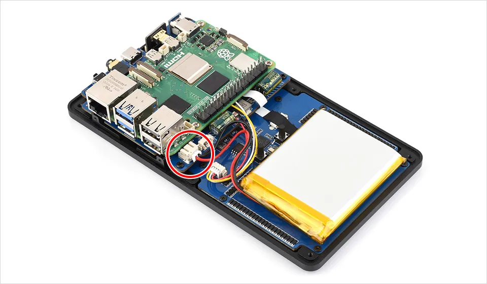
When connecting the battery, the power LED may briefly light up and then turn off. This is normal behavior during power circuit initialization; the device remains powered off.
To power on, press the top power button once.
Step 5: Connect the Speaker and Install the Silicone Button
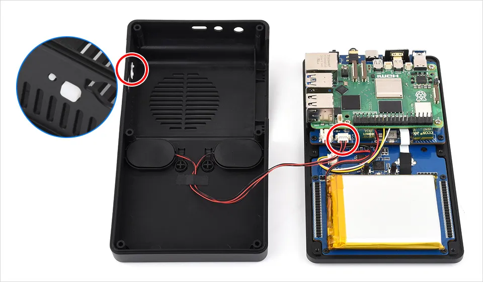
Connect the speaker to the 4PIN PH1.25 audio interface.
If you are installing a Raspberry Pi 5, attach the Pi 5 side silicone power button (accessory ⑪) to the side wall of the enclosure.
During installation, ensure the silicone button aligns properly with the power button on the Raspberry Pi 5 main board and returns smoothly after pressing. If the button feels too tight or the power-on response is not sensitive enough, you may trim (flatten) the inside of the silicone button slightly and reinstall it.
Step 6: Secure the Back Cover
Before securing the back cover:
- If the black power button cap is already installed, remove it temporarily to avoid damaging it when reinstalling the back cover.
- Make sure cables are not pinched.
- Confirm that the back cover closes naturally.
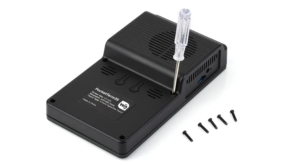
If the cover does not close easily, do not force it or tighten the screws; re-check the cable routing. Once confirmed, reinstall the 6 PM2.5×12 black screws and the black power button cap.
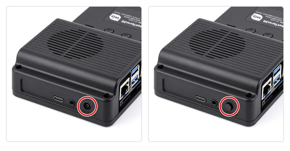
Step 7: Install the Side Panel
Based on your Raspberry Pi main board, select the corresponding side panel from accessories ②/③ and secure it with KM2×5 black screws.
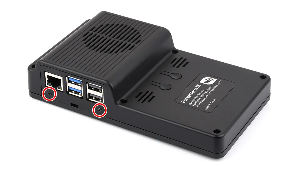
Software Configuration
If you purchased the pre-assembled version (PocketTerm35-Pi4 / Pi5):
It is ready to use out of the box, no additional configuration required
- Default username:
pi - Default password:
raspberry
Method 1: Flash Official Image and Configure
Connect the TF card to the PC, download and use Raspberry Pi Imager to flash the corresponding system image.
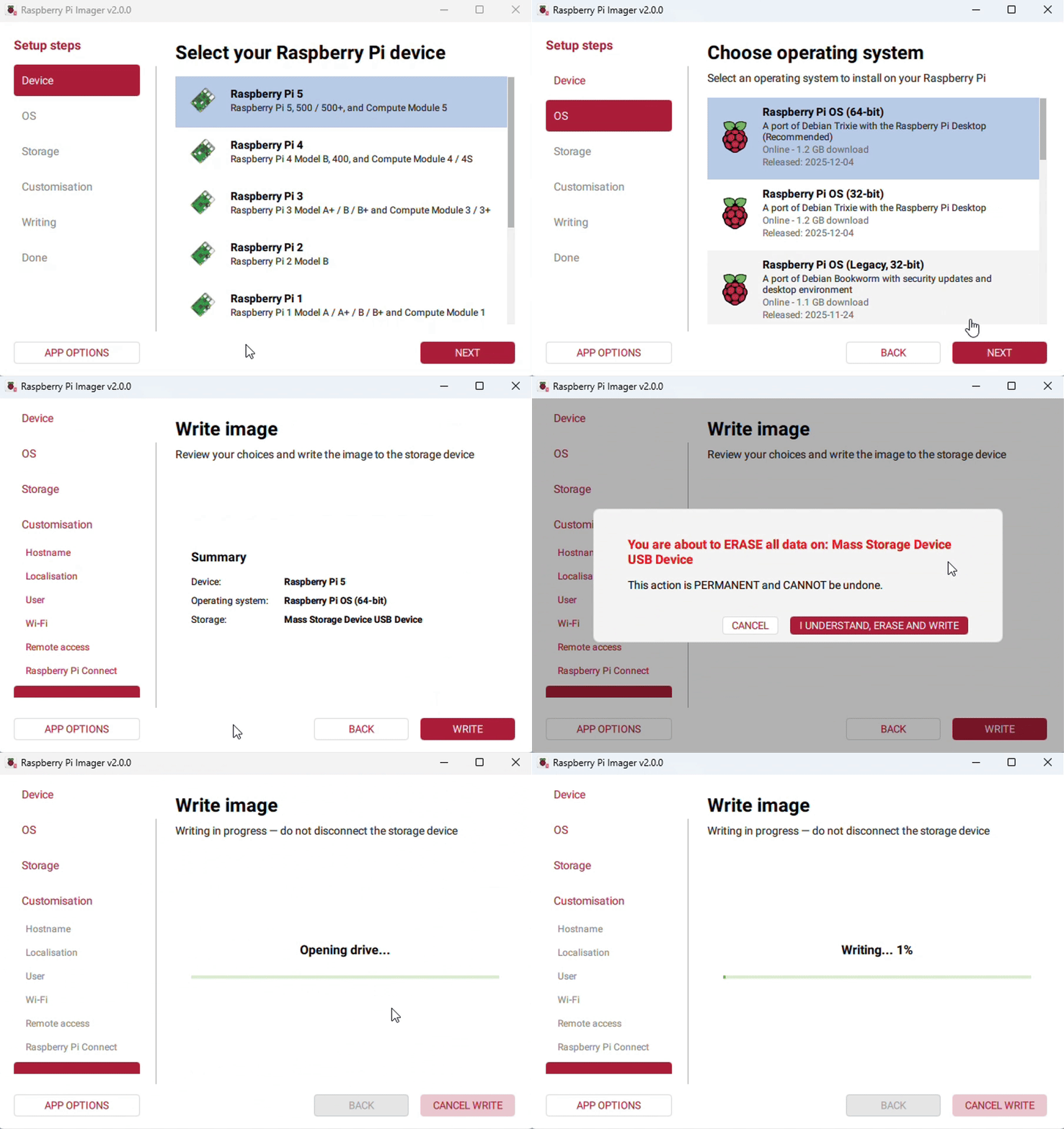
After flashing, open the config.txt file in the root directory of the TF card and add the following lines at the end of config.txt.
dtparam=i2c_arm=ondtoverlay=waveshare-35dpi-4bdtoverlay=waveshare-35dpi-5bdtoverlay=dwc2,dr_mode=hostDownload the PocketTerm35 DTBO file and unzip it, then copy the extracted .dtbo file to the overlays directory (/boot/overlays/).
Save and safely eject the TF card, insert the TF card into the Raspberry Pi, press the power button to start and use the device.
Method 2: Flash Pre-installed Image
- Download the PocketTerm35 pre-installed image: PocketTerm35-Pi4-Pi5 Pre-installed Image.
- Connect the TF card to the PC, and format the TF card using SDFormatter software.
- Open Win32DiskImager software, select the system image prepared in step 1, and click Write to flash the system image.
- After flashing, safely eject the TF card, insert it into the Raspberry Pi, press the power button to start and use the device.
Keyboard firmware update tutorial(video)
1】Enter the Linux terminal of the Raspberry Pi system
2】Unzip keyboard_circuitpython-bundle-10.x-260822.zip
sudo unzip keyboard_circuitpython-bundle-10.x-260822.zip
3】进入keyboard_circuitpython-bundle-10-260822.x
cd keyboard_circuitpython-bundle-10.x-260822
4】Change the line ending (first time)
sed -i 's/\r$//' deploy_keyboard.sh
5】Add execute permission (first time)
chmod +x deploy_keyboard.sh
6】Press and hold the BOOT button, then press the RESET button, and then release them in sequence to enter the "RP2 Boot" device.
RPi-RP2 can be seen on the screen.

Button location:
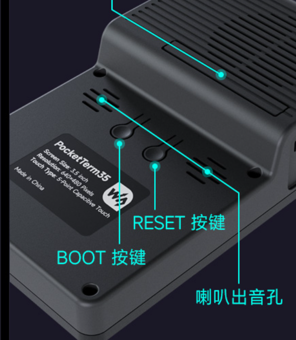
7】Execute the burning script
./deploy_keyboard.sh
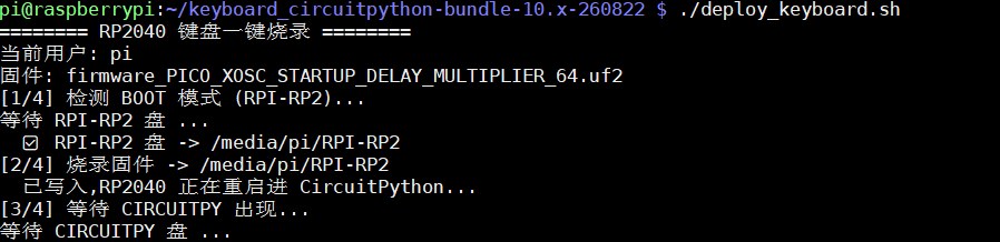
When the process reaches the point of waiting for the CIRCUITPY disk, press and hold the RESET button for 1-2 seconds, then release it. Repeat this process until the CIRCUITPY disk appears on the screen.
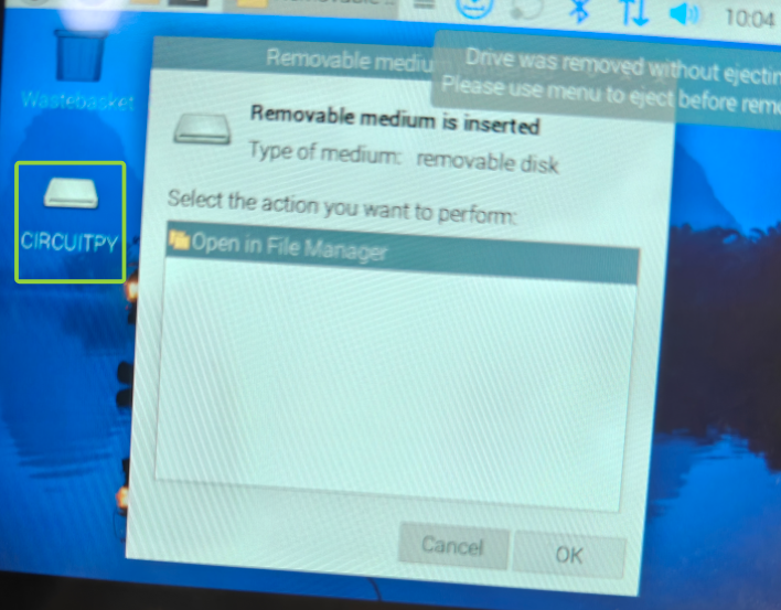
The script will then continue to execute.
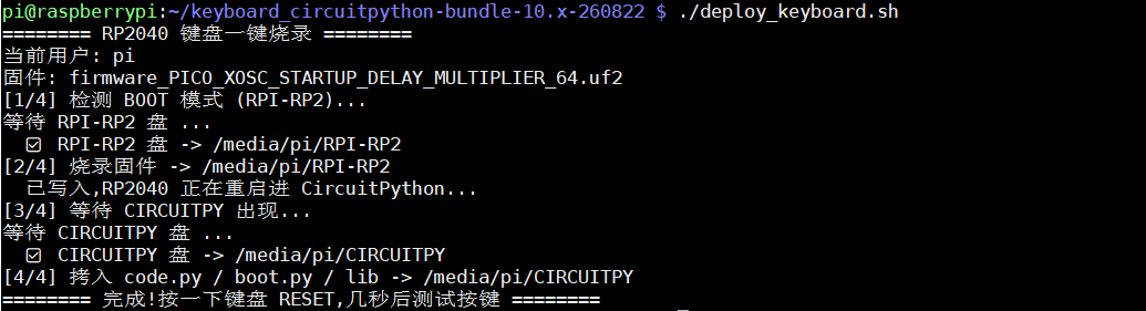
Until the execution is complete as shown in the figure
8】After the process is complete, press the RESET key to test the keyboard.