


- sales/support
Google Chat:---
- sales
+86-0755-88291180
- sales01
sales@spotpear.com
- sales02
dragon_manager@163.com
- support
tech-support@spotpear.com
- CEO-Complaints
zhoujie@spotpear.com
- Only Tech-Support
WhatsApp:13246739196
- Purchase/Shipping/Refund
WhatsApp:13424403025
- HOME
- >
- ARTICLES
- >
- Common Moudle
- >
- ESP
ESP32-MINI-NANO-Drone-B User Guide
1. Project Overview
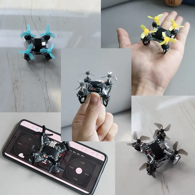
A super-compact quadcopter based on an ESP32 development board, featuring a built-in web remote controller and also supporting app and physical remote control.
Specifications
- Main controller: ESP32-S3-SUPERMINI
- Wheelbase: 50mm
- Weight: approximately 25 grams (including standard battery)
Quick start
III. Project Replication
Replication takes only three steps:
- Hardware assembly
- Software flashing
- Simple debugging
Step 1: Hardware Assembly
1. Download the [Bill of Materials table] from the attachments on this page, prepare the materials according to the BOM, and fabricate the PCB.
Design drawings, schematic diagrams:https://pro.lceda.cn/editor#id=a3328da24c31463983d68b78a7c95b36
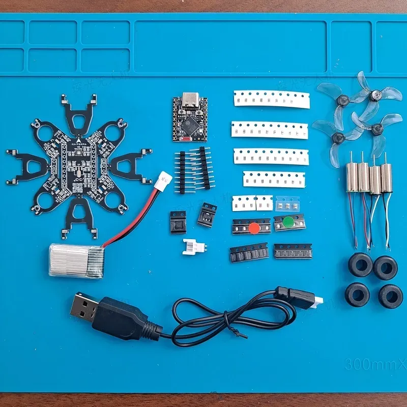
The PCB thickness should preferably be 1.2 mm, as the socket dimensions of the base are designed for a 1.2 mm thickness.
For the main components, try to purchase ones of better quality. The quality of accessories varies, which will directly affect the build results.
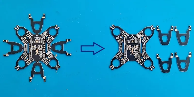
2. Separate the PCB. The front, back, left, and right sections are the motor mounts, and the middle section is the main controller board. Since panelized PCBs cannot use free coupons, the PCB is not pre-separated. Before assembly, separate the main controller board from the motor mounts. You can use tools to help; flush cutters make it easy to cut them apart.
3. Solder the components.
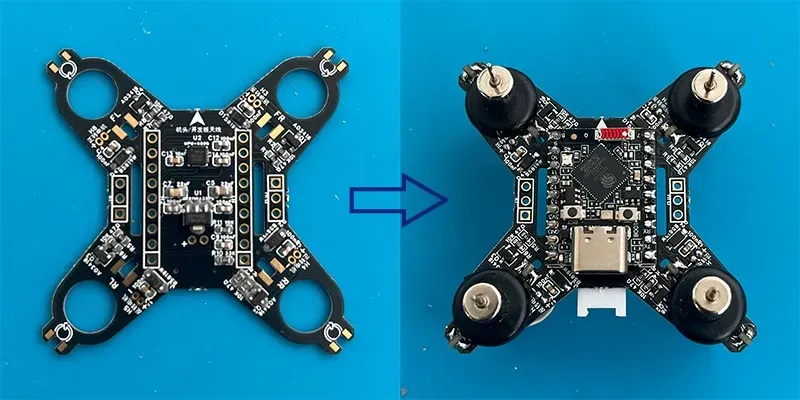
After soldering is complete, it is recommended to use a multimeter to briefly test the circuit for cold solder joints or short circuits, and confirm there are no issues before applying power.
4. Solder the motor mounts.
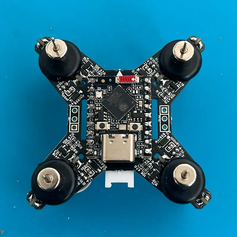
The motor mounts can effectively protect the drone when it loses control and also serve as the support for the entire aircraft. Installation is recommended. Solder pads are provided near the brackets; reinforce them with solder.
What it looks like after soldering
5. Install the motors.
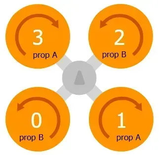
The motor rotation direction must follow the specified direction. The PCB has silkscreen markings indicating the corresponding direction, and the two diagonal motors must rotate in the same direction.
It is recommended to use two motors with black-and-white wires and two with red-and-blue wires, so the colors make installation more intuitive; alternatively, four motors with the same wire color can be used.
The motors are secured to the bracket with rubber rings, or fixed directly with hot glue.
Motor rotation direction reference:
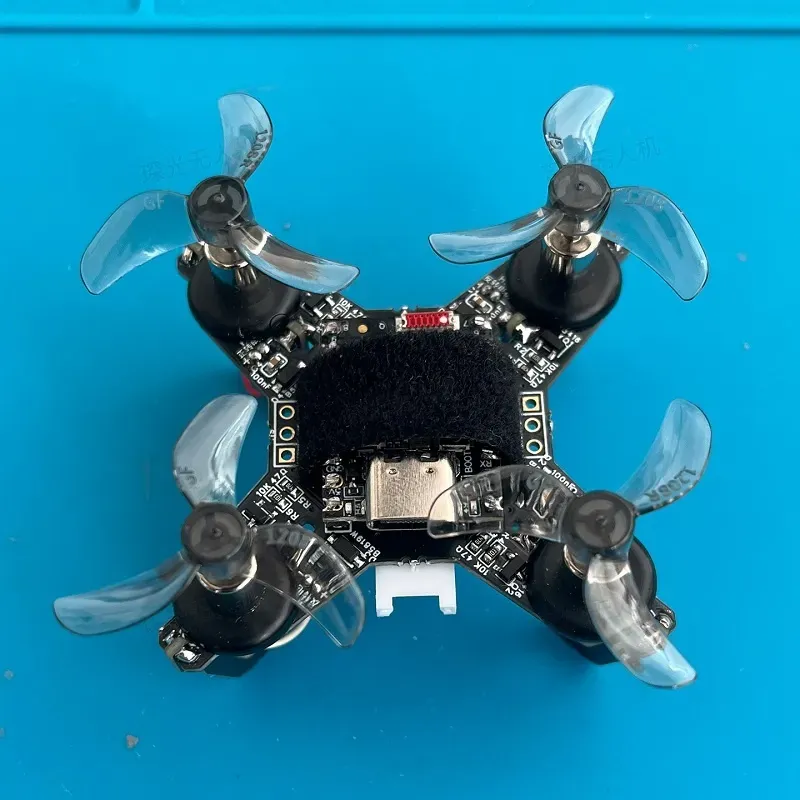
6. Install the propellers.
The propellers must also be installed in the specified direction! When the motor rotates in the marked direction, the higher side of the propeller should face forward and blow air downward. The diagonal propellers must also face the same direction. Refer to the installation direction shown in the figure below.
The safest approach is to complete debugging, arm the motors, and confirm that all four propellers blow air downward.
The mechanical strength of the motors and propellers is limited. Do not use excessive force during installation; tightening them securely is sufficient.
Step 2: Software Flashing
1. Download the compiled BIN firmware file.
E1_Nano firmware 20261027.bin
2. Use a USB cable to connect the ESP32 development board to the computer.
When the development board is connected to the computer for the first time, it usually does not automatically enter download mode and will keep disconnecting. Hold down the BOOT button and then connect it to the computer.
3. Flash using the official Espressif tool.
Flashing tool download address:https://docs.espressif.com/projects/esp-test-tools/zh_CN/latest/esp32/production_stage/tools/flash_download_tool.html
Flash settings:
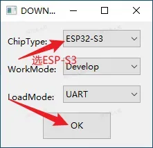
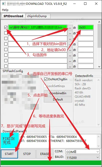
If you don't know which COM port to use, plug and unplug the development board and see which COM port changes—select that one.
Step 3: Debugging and Takeoff
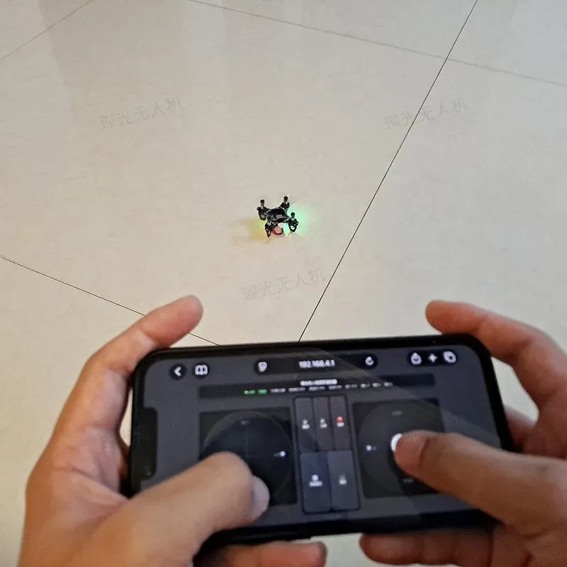
1. Connect the battery to the drone, and connect your phone to the drone's Wi-Fi: Drone_WIFI, password: 12345678. Some phones have an automatic network optimization feature that automatically switches between Wi-Fi and mobile data, so this needs to be disabled; or a more direct method: turn off mobile data on your phone.
2. Open your phone's browser and enter the address.:http://192.168.4.1 Confirm and open the remote control interface.
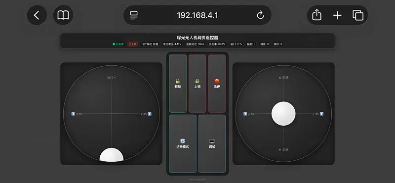
In the web remote controller, click the "Debug" button. In the debug interface that pops up, you can enter debug commands. It is recommended to remove the propellers before debugging.
- Calibrate the IMU (mandatory). Enter the debug command "ca" and position the drone as prompted. Refer to this prompt:
1/6 Level placement: Nose facing forward (normal flight direction), bottom facing down, place it level on a flat surface, ensuring it is completely level with no tilt. Keep it still; calibration will begin after 8 seconds.
Level calibration complete. Please continue.
2/6 Nose up: Keep the nose facing forward, point the nose toward the sky, tail facing down and touching the support surface, perpendicular to the ground. Keep it still; calibration will begin after 8 seconds.
Nose-up calibration complete. Please continue.
3/6 Nose down: Keep the nose facing forward, point the nose toward the ground and touching the support surface, tail facing up, perpendicular to the ground. Keep it still; calibration will begin after 8 seconds.
Nose-down calibration complete. Please continue.
4/6 Right side down: Keep the nose facing forward, place the right side of the aircraft facing down and touching the support surface, left arm facing up, perpendicular to the ground. Keep it still; calibration will begin after 8 seconds.
Right-side-down calibration complete. Please continue.
5/6 Left side down: Keep the nose facing forward, place the left side of the aircraft facing down and touching the support surface, right arm facing up, perpendicular to the ground. Keep it still; calibration will begin after 8 seconds.
Left-side-down calibration complete. Please continue.
6/6 Upside-down placement: Keep the nose facing forward, completely flip the aircraft so the top faces down and the bottom faces up, in a level upside-down position. Keep it still; calibration will begin after 8 seconds.
✓ All calibration complete! Set the aircraft upright and run the "ps" command to check the calibration results.
After calibration is complete, set the drone upright (top facing up) and enter the command "ps" to check the calibration results. You will see something like:
roll: 0.521120 pitch: -0.062948 yaw: 82.711197
roll/pitch close to 0 indicates successful calibration. The normal range is within ±0.5°, the acceptable range is within 2, and if it exceeds 5, recalibration is required. yaw can be ignored; the MPU6500 has no magnetometer, so the yaw axis is a virtual computed value.
IMU calibration only needs to be done once. After that, it does not need to be redone unless there is a significant deviation, hardware replacement, or firmware rewrite.
- Test the motors (optional). First remove the propellers from the motors to avoid injury! Enter the commands "mfl/mfr/mrl/mrr" respectively, corresponding to the front-left, front-right, rear-left, and rear-right motors, and observe whether the four motors rotate normally.
If the phone screen is too small for convenient debugging, you can also use Arduino or GQC for debugging. Refer to the content in the "In-Depth Study" section.
4. Take off. Click the arm button, push the throttle, and take off!
IV. In-Depth Study
If you are only doing a simple replication, the following sections can be ignored.
This project is licensed under the CC BY-NC-SA open-source license. Commercial use is prohibited without authorization.
Related resources
Hardware and software documentation, FAQ:http://docs.cherglowtech.com/e-series/e1-nano
Companion ground station:https://gc.cherglowtech.com/
Open-source flight controller source code:https://github.com/songge8/CF-Drone
The flight controller software is developed using Arduino. You can use Arduino for development and compilation, and the console built into the Arduino IDE can also be used for aircraft debugging.
Reserved interfaces
The main board has two reserved data interfaces, by default for the remote control receiver and as a spare. They can be used to connect external devices such as a remote control or to supply power to external devices.
Supports physical remote control, mobile app remote control, and MAVLink protocol remote control.
RC hobby remote control
The remote control receiver interface reserved on the main board supports the mainstream CRSF (ELRS) / SBUS remote control protocols. SBUS has been implemented with software inversion, so no hardware inverter is needed; ELRS/CRSF supports one-way control input, and you only need to connect the receiver's GND, 5V, and TX → the drone's G, V, and IO4.
Physical remote control setup method:
- Ensure the remote control and receiver are properly connected and the receiver protocol is set correctly.
- Connect the drone and the receiver.
- Set the receiver interface protocol and corresponding baud rate via console commands: RC_PROTOCOL, remote control protocol, 0=SBUS, 1=CRSF/ELRS (default); RC_BAUD, remote control serial port baud rate (bps), SBUS=100000, CRSF=420000 (default).
- Calibrate the remote control; use the CR command in the console and follow the prompts.
- Push the left stick fully to the bottom right to arm, and fully to the bottom left to disarm.
QGC mobile app
The app is available on the QGC official website.https://qgroundcontrol.com/
In addition to controlling the aircraft, the APP's Analyze Tools → MAVLink Console can also be used for flight controller debugging.
MAVLINK
The firmware supports the MAVLink protocol.
FAQ
Polarized component connection tips
Component positions and orientations may differ between hardware versions; refer to the actual PCB silkscreen.
- For diodes, the vertical line on the component marks the negative terminal, corresponding to the vertical line on the PCB silkscreen.
- For LEDs, the green leg on the front / the arrow direction on the back of the component indicates the negative terminal, corresponding to the pointed end of the PCB silkscreen.
- For electrolytic capacitors, the black marking on the component indicates the negative terminal; just match the shape of the component's bottom to the PCB silkscreen shape.
Component soldering positions
Any of the following methods can be used.
- The PCB has the reference designator and value printed for each component. Locate the corresponding position by the reference designator or value. (Recommended)
- Interactive online component location map https://pcbbom.cherglowtech.com/pcb/E1Nanov1.5Y
- PCB design drawing
The development board keeps disconnecting and reconnecting when connected to the computer, or keeps making the "ding-dong" connection sound.
The development board has not entered download mode. Hold down the BOOT button, connect it to the computer, and then release the BOOT button.
Unable to download / stuck at syncing when flashing firmware.
The flashing process takes about several tens of seconds. If an error occurs, or if it finishes too quickly or takes too long to complete, troubleshoot item by item according to the following:
Plug the data cable directly into the computer's USB port; do not use a USB hub or docking station.
It is recommended to use an Android phone data cable. Some cables only support charging and have no data transfer function.
Do not open Arduino and the Espressif flashing tool at the same time, as the serial port will be occupied.
Confirm that the correct development board model is selected in the flashing tool, and check that the development board model displayed in the title bar of the flashing tool is ESP32-S3.
The development board may not have entered download mode. Perform the following steps:
Plug the development board into USB, open the ESP32 flashing software, select the development board's serial port, hold down the BOOT button on the development board, click START in the flashing software, and release the BOOT button once you see it start connecting. The development board will then enter download mode.Confirm that the firmware is for the correct model and was downloaded from official channels (engineering documentation, QQ group files, etc.). Third-party firmware is not supported, and MINI/Nano firmware is not interchangeable.
The flashing address is "0x00", where "0" is the Arabic numeral and "x" is the English letter; other characters cannot be used as substitutes.
Confirm that the correct development board COM port is selected. The development board COM port must be selected from the list and cannot be entered manually.
Drone Wi-Fi cannot be found / cannot be connected.
Usually, the drone's Wi-Fi signal appears within a few tens of seconds after power-on. Your phone may take some time to refresh the signal list, so there may be a delay. If it does not appear for a long time, please troubleshoot by following the steps below.
Do not plug the development board into the drone; connect it to the USB data cable alone to avoid the development board failing to start normally due to a circuit short, which would interfere with troubleshooting.
Confirm that the firmware has been written correctly. It is recommended to use the latest firmware. Sometimes poor contact at the computer port or with the data cable can cause write errors, which may lead to Wi-Fi connection failure or incorrect password. You can try changing the computer port/data cable, clearing the development board's storage, and then reflashing the firmware.
The correct default Wi-Fi name: Drone_WiFi, password: 12345678 (marked on the aircraft body).
If you have changed the account and password, connect using the modified account and password. If you forget the password, you can clear the development board's storage and reflash the firmware to reset it.
A Wi-Fi signal starting with ESP_XXXXXX is the development board's factory default signal, indicating that the firmware was not successfully flashed. Flash the firmware and try again.If the battery level is too low, it may not be able to power the Wi-Fi.
After the firmware is correctly written, power the development board back on, and the red indicator light on the development board will flash once. If the blue indicator light does not light up or stays on continuously, it means the firmware was not successfully written or the program did not run successfully. You can seek help in the technical exchange group.
The web remote control won't open.
Before connecting, first confirm that the drone firmware has been flashed successfully.
Confirm that your phone is connected to the drone's Wi-Fi and that mobile data has been turned off.
Web remote control address http://192.168.4.1
All symbols in the web remote control address must be English symbols; do not use Chinese symbols.
Some browsers distinguish between the address bar and the search bar; the address must be entered in the address bar.
IMU fault alert
In this project, the terms IMU, gyroscope, attitude sensor, and accelerometer all actually refer to the IMU (MPU6500).
This alert indicates that the IMU (MPU6500) has a cold solder joint, a short circuit, or is not working properly.
"Accelerometer not calibrated" prompt when arming
Use the "ca" command in the web remote debugging console or the console, calibrate the IMU according to the prompts, and then operate again.
Normal range for IMU calibration data.
Use the ps command to check the attitude data after calibration. If roll/pitch is close to 0, the calibration is successful. The normal range is within 0.5, the acceptable range is within 2, and if it exceeds 5, recalibration is required. yaw can be ignored; the MPU6500 has no magnetometer, so the yaw axis is a virtual computed value.
After IMU calibration, the ROLL value shows 170+.
Set the aircraft body upright (development board facing up, bottom of the aircraft facing down), then run the PS command again.
If the PS command still shows 170+ after the aircraft is placed upright, it means the calibration is incorrect and calibration needs to be performed again.
After IMU calibration, all data is NAN, or the PS command shows that the attitude data roll/pitch is all 0.000.
IMU (MPU6500 module) has cold solder joints, short circuits, or is not working properly. (New firmware will indicate an IMU fault.)
The IMU gets stuck at the first step for a long time during calibration, and the remote control may even disconnect.
IMU (MPU6500 module) has poor/cold solder joints, short circuits, or is not functioning properly. (New firmware will report an IMU fault.)
Does the IMU need to be calibrated every time it is powered on?
IMU calibration only needs to be done once. After that, it does not need to be redone unless there is a significant deviation, hardware replacement, or firmware rewrite.
Will the motor spin if no operation is performed after power-on?
Before the development board is flashed with firmware, some pins may have default pull-ups, which could start the motor. Do not power on before the firmware is flashed, or power on with the development board removed.
Under normal conditions, the motor will not spin if no operation is performed after power-on; it will only spin after arming/unlocking.
If the motor spins when no operation is performed after power-on, check the drive circuit for that motor channel. This situation may be caused by:
- A cold solder joint on the 10K resistor (most common; if you cannot determine the cause, you can directly re-solder it);
- The MOSFET is burnt out and stuck in a conducting state (burn marks such as a burnt dot are usually visible on the component).
After arming (at idle speed), some motors spin while others do not.
You need to test and troubleshoot the motor and circuit issues. Follow the steps below:
Use the web remote/console debug commands mfl/mfr/mrl/mrr to test each motor in turn (remove the propellers before testing!). If a motor spins normally, it means both the motor and the drive circuit hardware are fine; if it does not spin, it means that motor or its drive circuit is not working properly, and further troubleshooting is needed.
To test a motor individually, remove the motor and connect its positive and negative terminals directly to an adjustable power supply. If the motor spins at 1V, the motor is normal. If an adjustable power supply is not available, a 1.5V dry cell or a drone battery can be used instead.
If the motor does not spin when tested with the debug command but tests normal when tested individually, then the motor drive circuit is likely the problem. Check the corresponding motor drive circuit:
- Check whether the motor socket/solder joints are short-circuited (a resistance of less than 0.5Ω can be judged as a short circuit). If there is a short circuit, also check whether the MOSFET has been burnt out.
- Cold solder joints on the 47Ω resistor or MOSFET (most common; if you cannot determine the cause, you can directly re-solder them).
- The MOSFET is burnt out (burn marks such as a burnt dot are usually visible on the component).
- The 10K resistor is short-circuited (uncommon).
The motor speeds are inconsistent when the throttle is increased.
When the throttle is increased, the motor speeds are adjusted in real time through flight controller attitude calculations and other algorithms, rather than being directly powered by the battery, so differing motor speeds are normal. However, if the aircraft rolls over or cannot take off, please troubleshoot according to the rollover issue.
If you need to test the motors, use the web remote/console debug commands mfl/mfr/mrl/mrr.
The drone rolls over / some motors stop spinning / it cannot take off when the throttle is increased for takeoff.
Necessary conditions for a normal takeoff:
- The battery's actual discharge rate must be 25C or above (the official kit battery has been tested and meets this requirement).
- The battery has sufficient charge.
- The motor rotation direction must be correct.
- The propeller orientation must be installed correctly.
- The IMU calibration is correct, and the calibration error is within the acceptable range.
- There are no cold solder joints or short circuits in the circuit.
After troubleshooting the above issues, the drone should generally be able to take off normally.
How do I operate the web remote control?
The web remote control layout is Mode 2 (American hand). You can find some FPV drone control tutorials online to learn.
The left stick's up/down controls throttle, and left/right controls yaw; the right stick's up/down controls pitch, and left/right controls roll.
These are the professional terms used for drones, which beginners may misunderstand, so in the new firmware they have been changed to plain language:
Left stick — Up: throttle up; Down: throttle down; Left: turn left; Right: turn right;
Right stick — Up: move forward; Down: move backward; Left: move left; Right: move right.
Flight mode description
Acro (FPV mode): manual throttle, which automatically returns to zero when the throttle is released; manual attitude control, with the attitude not self-leveling.
Angle (FPV mode): manual throttle, which automatically returns to zero when the throttle is released; manual attitude control, with the attitude self-leveling automatically.
Altitude Hold (similar to DJI flight mode; requires a sensor module, which is automatically recognized once installed): automatic throttle, where the throttle controls ascent/descent, and releasing the throttle automatically maintains the altitude; manual control of the horizontal direction.
Position Hold (similar to DJI flight mode; requires a sensor module, which is automatically recognized once installed): automatic throttle, where the throttle controls ascent/descent, and releasing the throttle holds a fixed altitude and hovers; the horizontal position is automatically maintained and can be manually adjusted, and releasing the stick holds a fixed position and hovers.
"Taken over" alert
The drone allows only one remote controller to control it at a time. Close or disconnect the other remote controllers (multiple web remote control pages also count as multiple remote controllers).。
A small number of mobile browsers have special mechanisms, which may trigger false positives when there is only one web remote control page. Switching to another browser will resolve this.
Flight Distance / Altitude
Limited by motor power, the altitude is only a few meters. The horizontal range can theoretically reach hundreds of meters. However, without video transmission, flight must stay within visual line of sight. In practice, the aircraft becomes hard to see beyond several tens of meters.
Why is the battery dead upon arrival?
Batteries are best stored at half charge and will self-discharge over time, so they will not arrive fully charged. Please charge them fully before use.
The kit comes with a charging cable. A 5V 1A charger is recommended. A standard battery takes about half an hour to fully charge. The cable shows a red light while charging and turns off once fully charged.
Indicator Light Blinking / Not Illuminated
The LED next to the battery connector is the power indicator. It should stay solid on after power‑up. If it is off or blinking, there is a power supply issue. The blue LED on the development board is the board power indicator; it should blink after power‑up (it may be dim).
The red LED indicates system status: one flash at startup for self-test, slow blinking for normal unlock, and fast blinking for alarms (low battery, remote signal loss, etc.).
The rear LED indicates motor status: off before unlocking, on when the motor is powered, and off when the motor is powered off.
The rear motor indicator may vary in brightness or flicker with motor speed. This is normal, as motor speed is dynamically controlled by the algorithm after unlocking.
MOSFET Burnout
Possible Causes of MOSFET Failure:
- Motor wiring short circuit;
- Motor stall;
- Diode installed in reverse or with a cold solder joint;
Download
Firmware
Third-party tools and drivers
ESP32 flashing tool
[Tutorial Navigation]
- 1. Project Overview
- Specifications
- Quick start
- FAQ
- Polarized component connection tips
- Component soldering positions
- The development board keeps disconnecting and reconnecting when connected to the computer, or keeps making the "ding-dong" connection sound.
- Unable to download / stuck at syncing when flashing firmware.
- Drone Wi-Fi cannot be found / cannot be connected.
- The web remote control won't open.
- IMU fault alert
- "Accelerometer not calibrated" prompt when arming
- Normal range for IMU calibration data.
- After IMU calibration, the ROLL value shows 170+.
- After IMU calibration, all data is NAN, or the PS command shows that the attitude data roll/pitch is all 0.000.
- The IMU gets stuck at the first step for a long time during calibration, and the remote control may even disconnect.
- Does the IMU need to be calibrated every time it is powered on?
- Will the motor spin if no operation is performed after power-on?
- After arming (at idle speed), some motors spin while others do not.
- The motor speeds are inconsistent when the throttle is increased.
- The drone rolls over / some motors stop spinning / it cannot take off when the throttle is increased for takeoff.
- How do I operate the web remote control?
- Flight mode description
- "Taken over" alert
- Flight Distance / Altitude
- Why is the battery dead upon arrival?
- Indicator Light Blinking / Not Illuminated
- MOSFET Burnout
- Download