


- sales/support
Google Chat:---
- sales
+86-0755-88291180
- sales01
sales@spotpear.com
- sales02
dragon_manager@163.com
- support
tech-support@spotpear.com
- CEO-Complaints
zhoujie@spotpear.com
- Only Tech-Support
WhatsApp:13246739196
- Purchase/Shipping/Refund
WhatsApp:13424403025
- HOME
- >
- ARTICLES
- >
- Common Moudle
- >
- ESP
ESP32-C6-LCD-1.69 User Guide
Overview
Introduction
ESP32-C6-LCD-1.69 is a low-cost, high-performance MCU board designed by Waveshare. It is equipped with a 1.69inch LCD screen, a lithium battery charging chip, an audio codec chip, a six-axis sensor (three-axis accelerometer and three-axis gyroscope), RTC and other peripherals, which are convenient for development and embedding into the product.
Features
- Equipped with a high-performance 32-bit RISC-V processor with clock speed up to 160 MHz, and a low-power 32-bit RISC-V processor with clock speed as low as 20MHz
- Integrated Wi-Fi 6, Bluetooth 5, and IEEE 802.15.4 (Zigbee 3.0 and Thread) wireless communications with excellent RF performance
- Built-in 320KB ROM, 512KB HP SRAM, 16KB LP SRAM, and external 16MB Flash
- Type-C connector, easier to use
- Onboard 1.69inch LCD screen with a resolution of 240×280, 262K colors for clear color pictures
- Embedded with ST7789V2 driver chip, using SPI interface communication, minimizes required IO pins
- Onboard QMI8658 6-axis IMU (3-axis accelerometer and 3-axis gyroscope) for detecting motion gesture, step counting, etc.
- Built-in PCF85063 RTC chip, facilitating the implementation of RTC functionality requirements
- On-board RST, BOOT, and a side button with customizable function, allowing for custom function development
- Onboard 3.7V MX1.25 lithium battery recharge/discharge header
- Onboard ES8311 audio codec, microphone and speaker
- Bring out GPIO, I2C, USB, and UART pads for external device connection and debugging, allowing flexible configuration of peripheral functions
- Supports flexible clock, precise control with individual power settings for modules, enabling low-power modes for multiple scenarios
Hardware Description
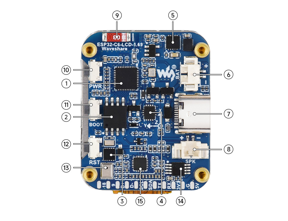
1. ESP32-C6 2. W25Q128JVSIQ 3. PCF85063 4. QMI8658 5. ETA6098 6. MX1.25 Lithium battery interface 7. Type-C port 8. MX1.25 Speaker interface 9. Onboard SMD antenna 10. PWR button 11. BOOT button 12. RST button 13. Microphone 14. NS4150B 15. ESP32-S3-WROOM-1-N16R8 |
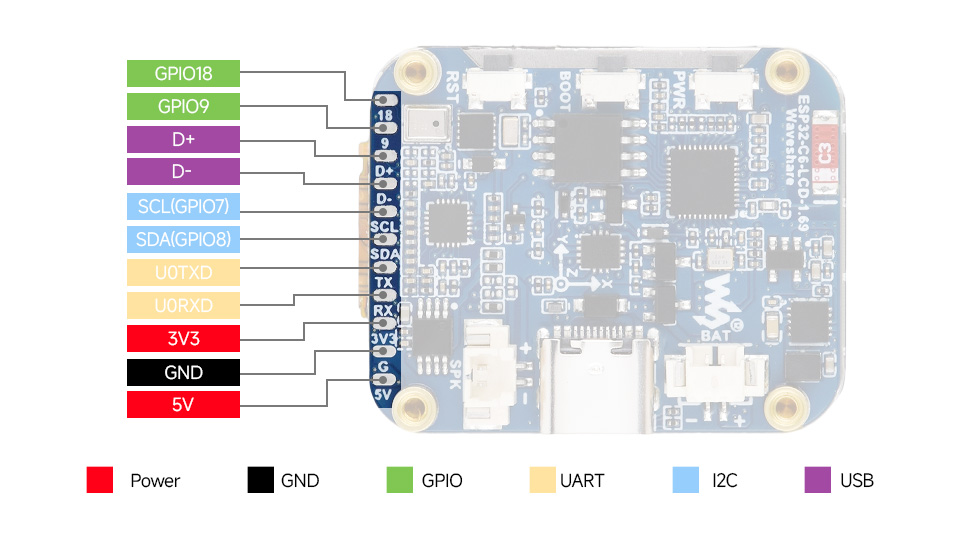
Pinout Definition
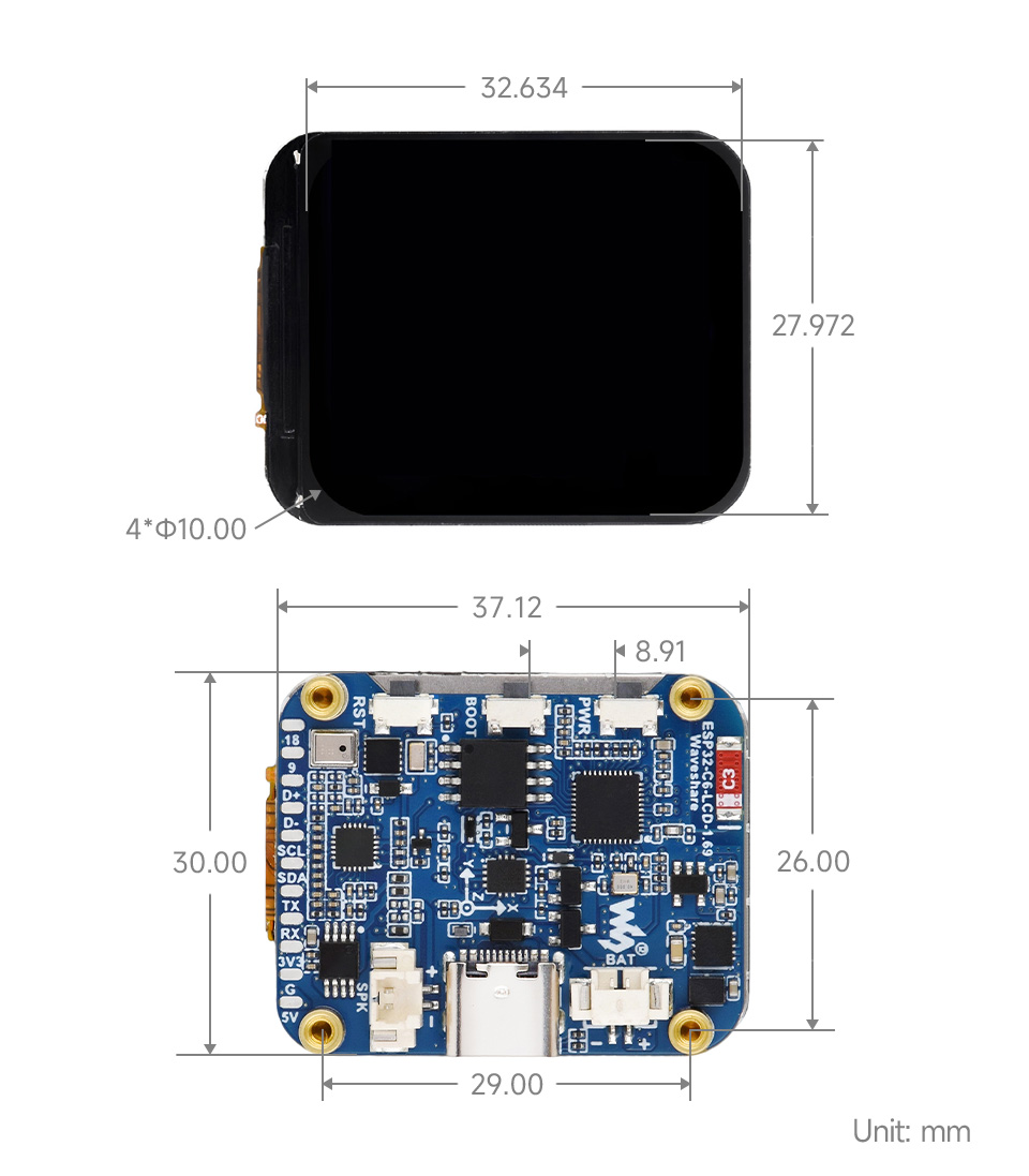
Dimensions
Usage Instructions
ESP32-C6-LCD-1.69 currently provides two development tools and frameworks, Arduino IDE and ESP-IDF, providing flexible development options, you can choose the right development tool according to your project needs and personal habits.
Development Tool
| Arduino IDEArduino IDE is an open source electronic prototyping platform, convenient and flexible, easy to get started. After a simple learning, you can start to develop quickly. At the same time, Arduino has a large global user community, providing an abundance of open source code, project examples and tutorials, as well as rich library resources, encapsulating complex functions, allowing developers to quickly implement various functions. |
| ESP-IDFESP-IDF, or full name Espressif IDE, is a professional development framework introduced by Espressif Technology for the ESP series chips. It is developed using the C language, including a compiler, debugger, and flashing tool, etc., and can be developed via the command lines or through an integrated development environment (such as Visual Studio Code with the Espressif IDF plugin). The plugin offers features such as code navigation, project management, and debugging, etc. |
Each of these two development approaches has its own advantages, and developers can choose according to their needs and skill levels. Arduino are suitable for beginners and non-professionals because they are easy to learn and quick to get started. ESP-IDF is a better choice for developers with a professional background or high performance requirements, as it provides more advanced development tools and greater control capabilities for the development of complex projects.
Components Preparation
- ESP32-C6-LCD-1.69 x1
- USB cable (Type-A male to Type-C male) x1
Working with Arduino
This chapter introduces setting up the Arduino environment, including the Arduino IDE, management of ESP32 boards, installation of related libraries, program compilation and downloading, as well as testing demos. It aims to help users master the development board and facilitate secondary development. ![]()
Environment Setup
Download and Install Arduino IDE
- Click to visit the Arduino official website, select the corresponding system and system bit to download
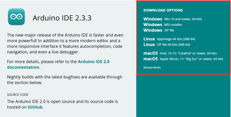
- Run the installer and install all by default
Install ESP32 Development Board
- Before using ESP32-related motherboards with the Arduino IDE, you must first install the software package for the esp32 by Espressif Systems development board
- According to board installation requirement, it is generally recommended to use Install Online. If online installation fails, use Install Offline.
- For the installation tutorial, please refer to Arduino board manager tutorial
| Board name | Board installation requirement | Version number requirement |
|---|---|---|
| esp32 by Espressif Systems | "Install Offline" / "Install Online" | ≥3.2.0 |
Install Library
- When installing Arduino libraries, there are usually two ways to choose from: Install online and Install offline. If the library installation requires offline installation, you must use the provided library file
For most libraries, users can easily search and install them through the online library manager of the Arduino software. However, some open-source libraries or custom libraries are not synchronized to the Arduino Library Manager, so they cannot be acquired through online searches. In this case, users can onlymanually install these libraries offline. - ESP32-C6-LCD-1.69 library file is stored in the demo, click here to jump:ESP32-C6-LCD-1.69 Demo
- For library installation tutorial, please refer to Arduino library manager tutorial
- ESP32-C6-LCD-1.69 library file description
| Library Name | Description | Version | Library Installation Requirement |
|---|---|---|---|
| lvgl | LVGL graphical library | v8.4.0 or v9.2.2 | "Install Online" |
| GFX_Library_for_Arduino | GFX graphical library | v1.6.0 | "Install Online" |
| U8g2 | Graphical library | v2.35.30 | "Install Online" |
| SensorLib | Sensor library | v0.3.1 | "Install Online" |
| OneButton | Button library | v2.6.1 | "Install Online" |
Run the First Arduino Demo
New Project
- Run the Arduino IDE and select
File->New Sketch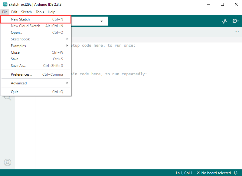
- Enter the code:
void setup() {
  // put your setup code here, to run once:
  Serial.begin(115200);
}

void loop() {
  // put your main code here, to run repeatedly:
  Serial.println("Hello, World!");
  delay(2000);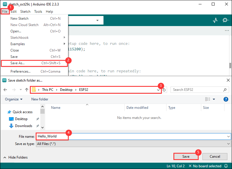
}- Save the project and select
File->Save As.... In the pop-up menu, select the path to save the project, and enter a project name, such as Hello_World, clickSave
Compile and Flash Demos
- Select the corresponding development board, take the ESP32S3 motherboard as an example:
①. Click to select the dropdown menu option Select Other Board and Port;
②. Search for the required development board model esp32s3 dev module and select;
③. Select COM Port;
④. Save the selection.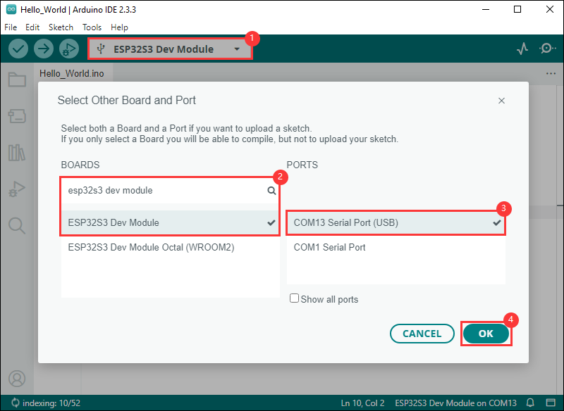
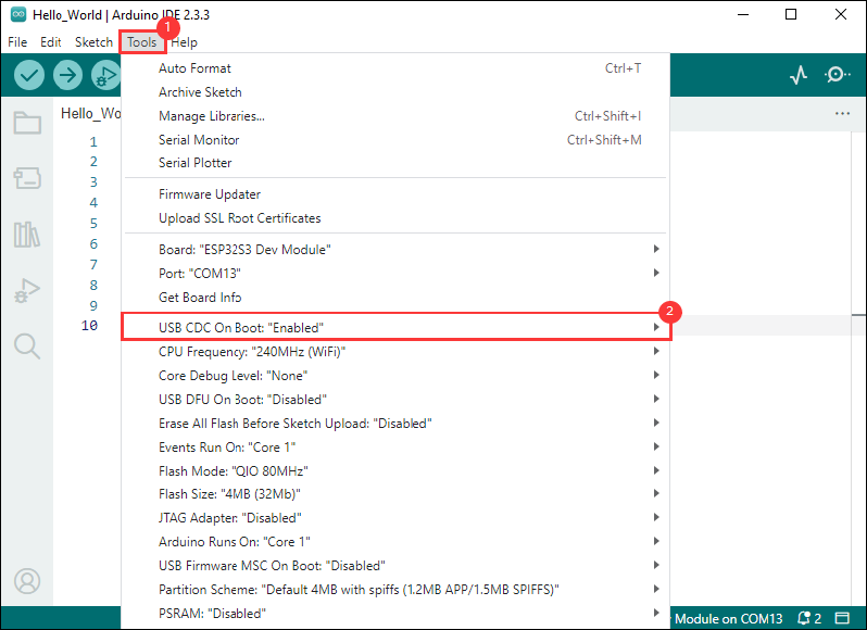
- If the ESP32S3 mainboard only has a USB port, you need to enable USB CDC, as shown in the following diagram:
- Compile and upload the program:
①. Compile the program; ②. Compile and download the program; ③. Download successful.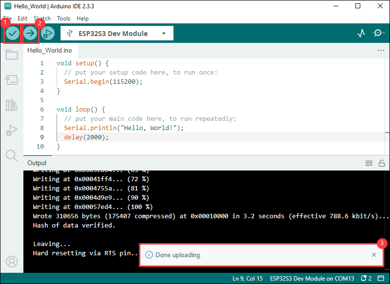
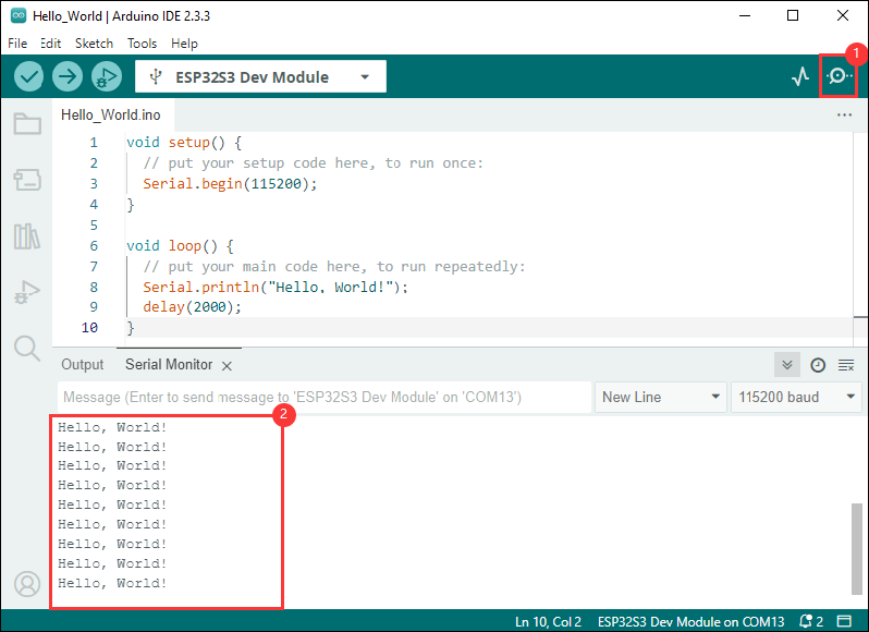
- Open the Serial Monitor window, and the demo will print "Hello World!" every 2 seconds, and the operation is as follows:
Demo

| Demo | Basic Description | Dependency Library |
|---|---|---|
| 01_audio_out | Play PCM audio data through I2S interface | --- |
| 02_button_example | Display battery voltage on the screen | OneButton |
| 03_battery_example | BOOT button click, double click, long press, etc. | OneButton |
| 04_es8311_example | Play the sound collected by the microphone in real time through the speaker | --- |
| 05_gfx_helloworld | Display HelloWorld on the screen | GFX_Library_for_Arduino |
| 06_gfx_pdq_graphicstest | Perform graphical tests and display the score | GFX_Library_for_Arduino |
| 07_gfx_clock | Display an analog clock dial on the screen | GFX_Library_for_Arduino |
| 08_gfx_u8g2_font | Display text in various languages by loading font libraries | GFX_Library_for_Arduino, U8g2 |
| 09_gfx_image | Display pictures on the screen | GFX_Library_for_Arduino |
| 10_esp_wifi_analyzer | Display WiFi band signal strength on the screen | GFX_Library_for_Arduino |
| 11_pcf85063_example | Display RTC time on the screen | GFX_Library_for_Arduino, SensorLib |
| 12_qmi8658_example | Display IMU data on the screen | GFX_Library_for_Arduino, SensorLib |
| 13_lvgl_arduino_v8 | LVGL v8 version demo | lvgl (v8.4.0), GFX_Library_for_Arduino, SensorLib |
| 14_lvgl_arduino_v9 | lvgl v9 version demo | lvgl (v9.3.0), GFX_Library_for_Arduino, SensorLib |
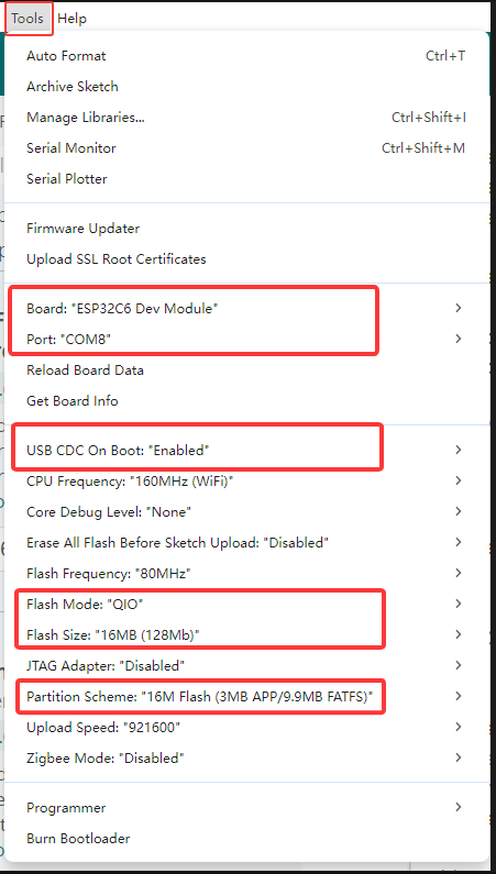
- ESP32-C6-LCD-1.69 Arduino Project Parameter Setting
01_audio_out
【Demo description】
This demo demonstrates that the ESP32-C6-LCD-1.69 plays PCM audio data.
【Code analysis】
- Set the audio data to play
i2s.write((uint8_t *)audio_data, AUDIO_SAMPLES * 2);
【Result demonstration】
- Nothing will be shown on the screen if you play the audio file
02_button_example
【Demo description】
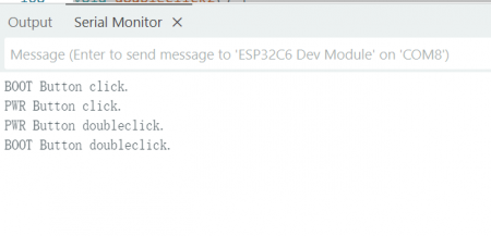
This demo demonstrates how to use the OneButton library to read the click, double-click, and long press states of the BOOT and PWM buttons, and print the states through the serial port.
【Code analysis】
- Bind callback functions
  button1.attachClick(click1);
  button1.attachDoubleClick(doubleclick1);
  button1.attachLongPressStart(longPressStart1);
  button1.attachLongPressStop(longPressStop1);
  button1.attachDuringLongPress(longPress1);
【Result demonstration】
- Nothing will be shown on the screen
- Open the serial port monitor
03_battery_example
【Demo description】
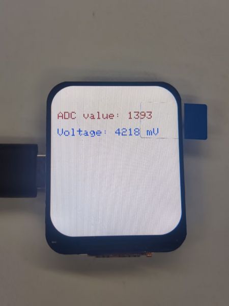
This demo demonstrates that ESP32-C6-LCD-1.69 displays the battery voltage in real time on the screen.
【Result demonstration】
04_es8311_example
【Demo description】
This demo demonstrates using the ESP32-C6-LCD-1.69 to drive the ES8311 audio codec to achieve real-time playback of microphone-collected sound through the speaker.
【Code analysis】
- After receiving the start signal, the audio data is read in a loop and played, and the playback is stopped after receiving the stop signal and waiting for the next start.
void es8311_test_task(void *arg)
{
  const int limit_size_max = 1600;
  uint8_t data[limit_size_max];
  while (1)
  {
    if (xSemaphoreTake(es8311_recording_BinarySemaphore, portMAX_DELAY) == pdTRUE)
    {
      while (1)
      {
        i2s.readBytes((char *)data, limit_size_max);
        i2s.write(data, limit_size_max);
        if (xSemaphoreTake(es8311_stop_BinarySemaphore, 0) == pdTRUE)
          break;
      }
    }
  }
}
【Result demonstration】
- Nothing will be shown on the screen
- Hold down the BOOT button without releasing it, and the speaker will play back the sound collected by the microphone in real time.
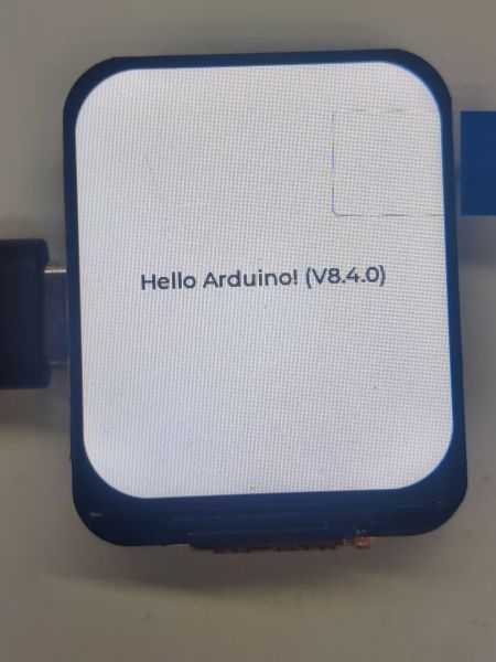
05_gfx_helloworld
【Demo description】
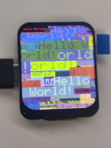
This demo demonstrates the ESP32-C6-LCD-1.69 using the GFX_Library_for_Arduino library to drive the screen and display HelloWorld on the screen.
【Code analysis】
- Configure the screen interface and screen resolution, etc.
Arduino_DataBus *bus = new Arduino_HWSPI(LCD_DC, LCD_CS, LCD_SCK, LCD_DIN);
Arduino_GFX *gfx = new Arduino_ST7789(
  bus, LCD_RST, 0 /* rotation */, true /* IPS */,
  240 /* width */, 280 /* height */,
  0 /* col offset 1 */, 20 /* row offset 1 */,
  0 /* col offset 2 */, 20 /* row offset 2 */);
【Result demonstration】
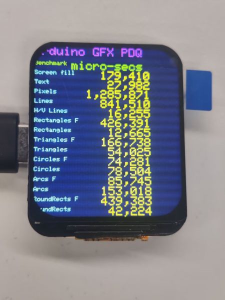
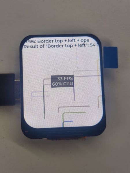
06_gfx_pdq_graphicstest
【Demo description】
This demo demonstrates that the ESP32-C6-LCD-1.69 uses the GFX_Library_for_Arduino library to drive the screen for the graphical test and displays the score
【Result demonstration】
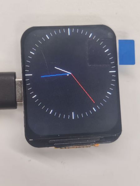
07_gfx_clock
【Demo description】
This demo demonstrates that the ESP32-C6-LCD-1.69 uses the GFX_Library_for_Arduino library to display an analog clock dial
【Result demonstration】
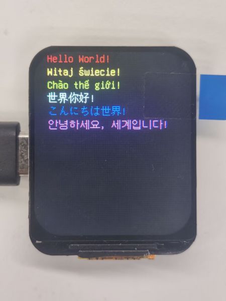
08_gfx_u8g2_font
【Demo description】
This demo demonstrates how ESP32-C6-LCD-1.69 uses GFX_Library_for_Arduino libraries to load font libraries to display them in various languages
【Result demonstration】
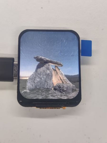
09_gfx_image
【Demo description】
This demo demonstrates how the ESP32-C6-LCD-1.69 uses the GFX_Library_for_Arduino library to display pictures on the screen.
【Hardware connection】
- Connect the board to the computer
【Preparation】
- Open Zimo221 Chinese character conversion software
- Import the image images/image_1.jpg and convert it, the image_1.h file will be generated
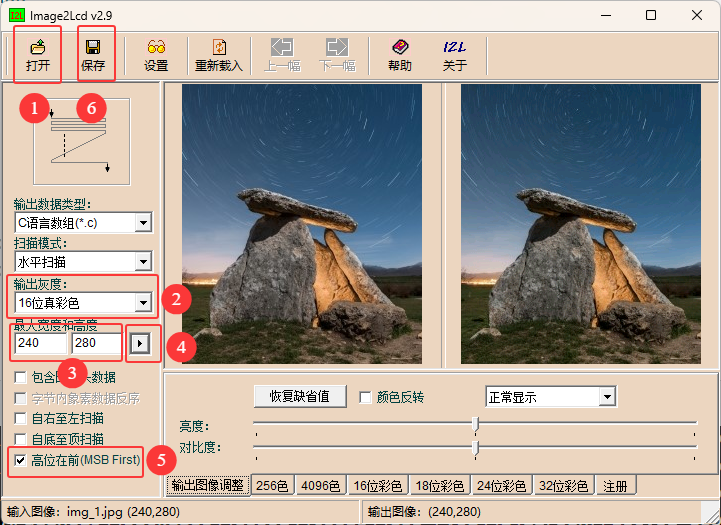
- Copy image_1.h to the project
- Set the image to be displayed
gfx->draw16bitBeRGBBitmap(0, 0, (uint16_t *)gImage_img, 240, 280);
【Result demonstration】

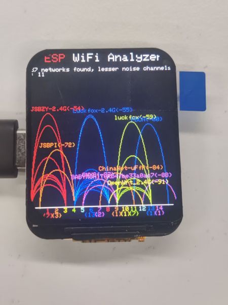
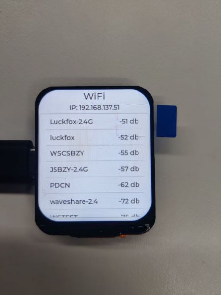
10_esp_wifi_analyzer
【Demo description】
This demo demonstrates the ESP32-C6-LCD-1.69 using a GFX_Library_for_Arduino library to display the signal strength of the WiFi band
【Result demonstration】
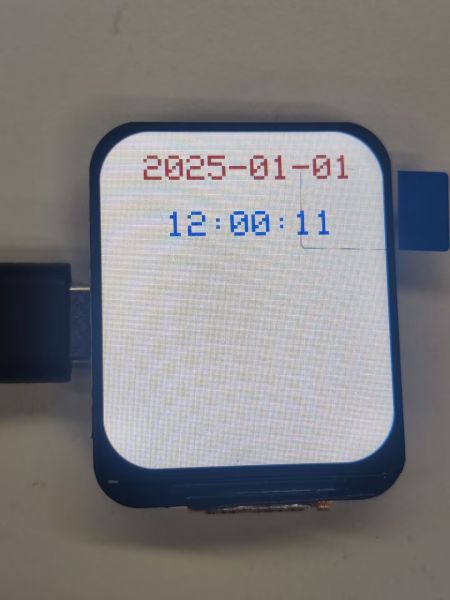
11_pcf85063_example
【Demo description】
This demo demonstrates that the ESP32-C6-LCD-1.69 obtains the time and date of the PCF85063 and displays it on the screen.
【Result demonstration】
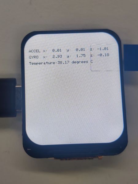
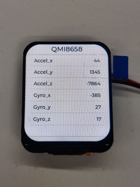
12_qmi8658_example
【Demo description】
This demo demonstrates that the ESP32-C6-LCD-1.69 acquires the Accel, Gyro, and temperature of the qmi8658 and displays them on the screen.
【Result demonstration】
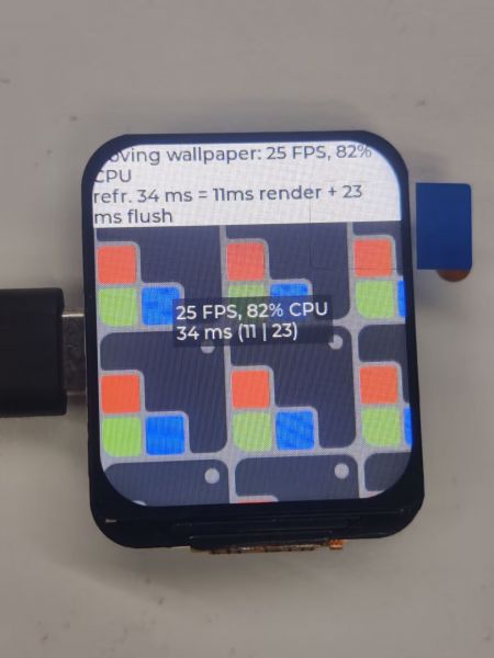
13_lvgl_example_v8
【Demo description】
This demo shows that ESP32-C6-LCD-1.69 runs lvgl v8 version demo.
【Result demonstration】
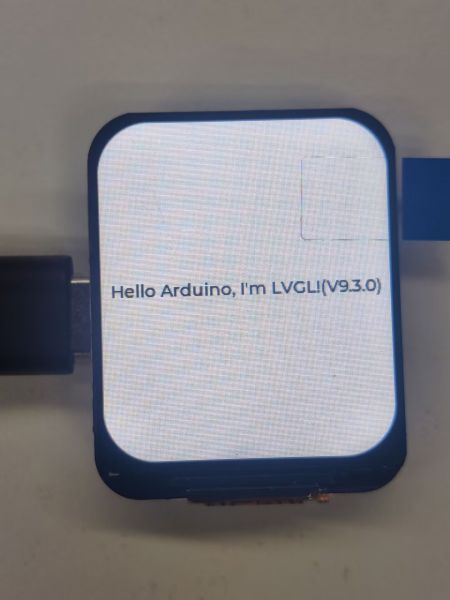
14_lvgl_example_v9
【Demo description】
This demo shows that ESP32-C6-LCD-1.69 runs lvgl v8 version demo.
【Result demonstration】
Working with ESP-IDF
This chapter introduces setting up the ESP-IDF environment setup, including the installation of Visual Studio and the Espressif IDF plugin, program compilation, downloading, and testing of demos, to assist users in mastering the development board and facilitating secondary development. 
Environment Setup
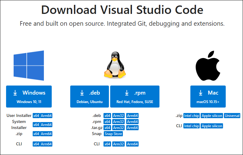
Download and Install Visual Studio
- Open the download page of VScode official website, choose the corresponding system and system bit to download
- After running the installation package, the rest can be installed by default, but here for the subsequent experience, it is recommended to check boxes 1, 2, and 3
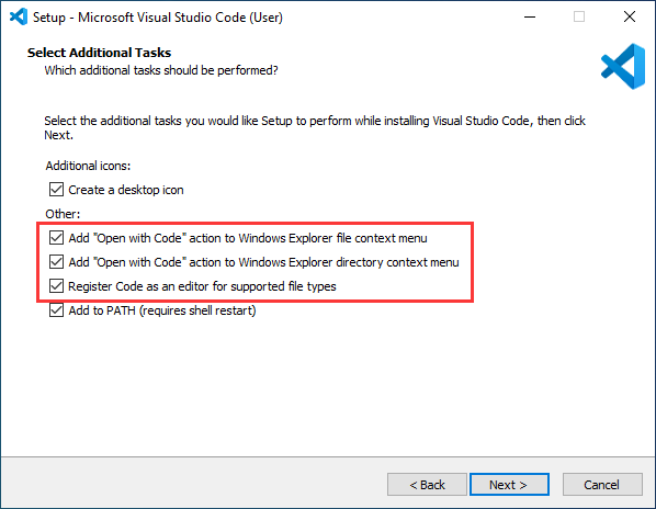
- After the first two items are enabled, you can open VSCode directly by right-clicking files or directories, which can improve the subsequent user experience.
- After the third item is enabled, you can select VSCode directly when you choose how to open it
Install Espressif IDF Plugin
- It is generally recommended to use Install Online. If online installation fails due to network factor, use Install Offline.
- For more information about how to install the Espressif IDF plugin, see Install Espressif IDF Plugin
- It is required to install ESP-IDF V5.4.0 or higher version.
Run the First ESP-IDF Demo
New Project
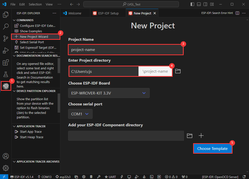
Create Demo
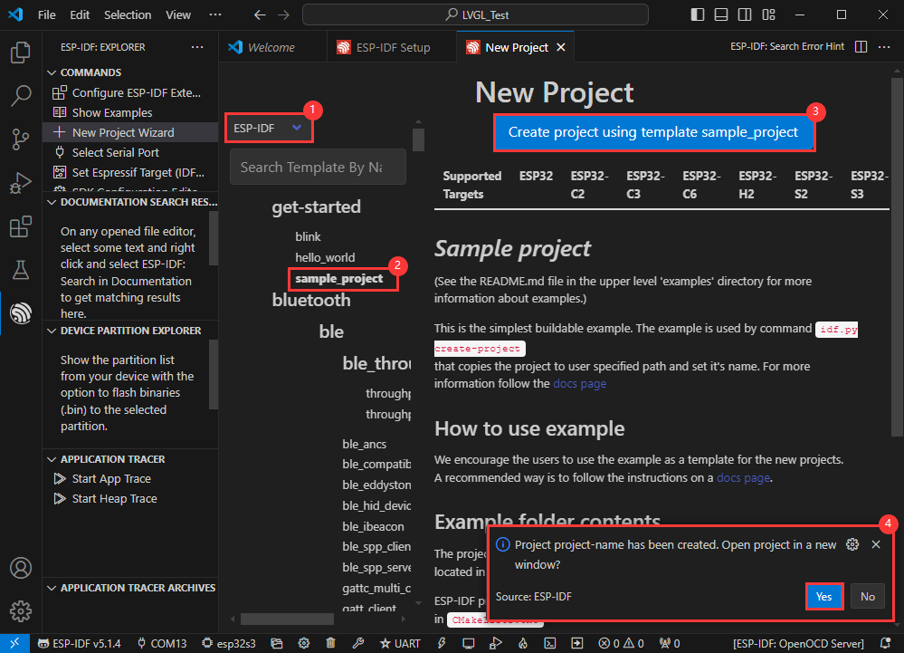
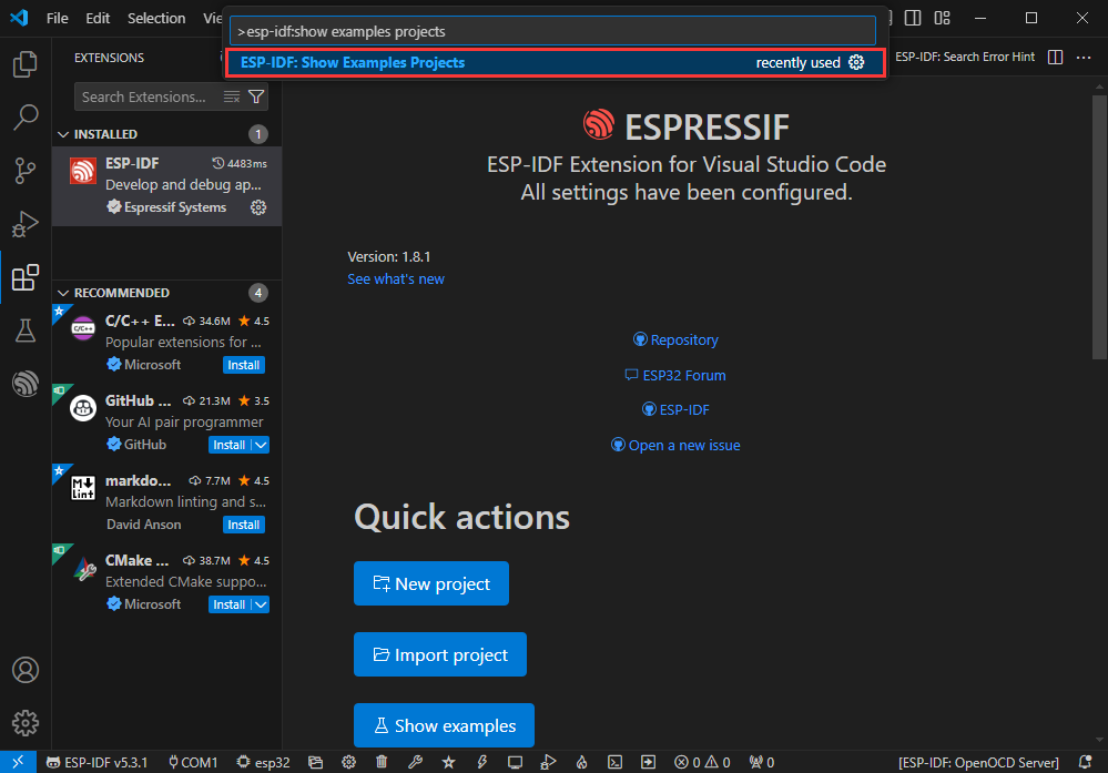
- Using the shortcut F1, enter esp-idf:show examples projects
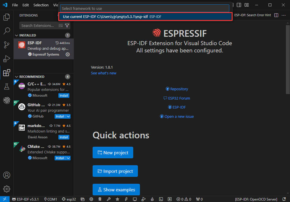
- Select your current IDF version
- Take the Hello world demo as an example
①Select the corresponding demo
②Its readme will state what chip the demo applies to (how to use the demo and the file structure are described below, omitted here)
③Click to create the demo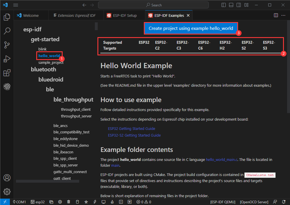
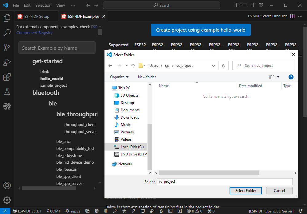
- Select the path to save the demo, and require that the demos cannot use folders with the same name
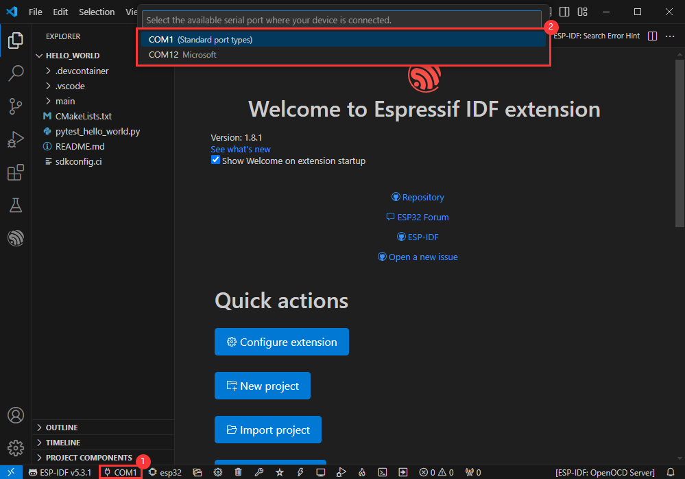
Modify COM Port
- The corresponding COM ports are shown here, click to modify them
- Please select the COM ports according to your device (You can view it from the device manager)
- In case of a download failure, please press the Reset button for more than 1 second or enter download mode, and wait for the PC to recognize the device again before downloading once more
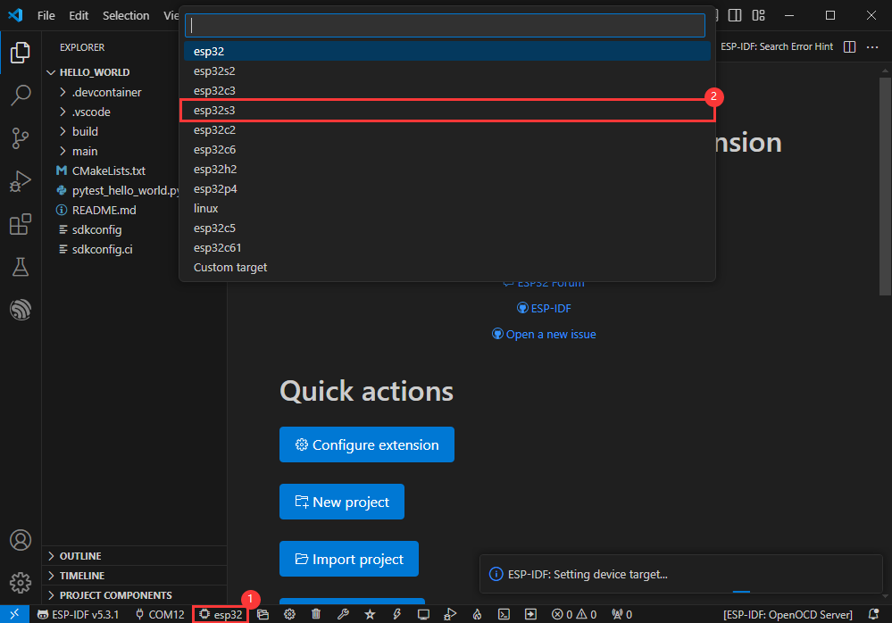
Modify Driver Object
- Select the object we need to drive, which is our main chip ESP32S3
- Choose the openocd path, it doesn't affect us here, so let's just choose one

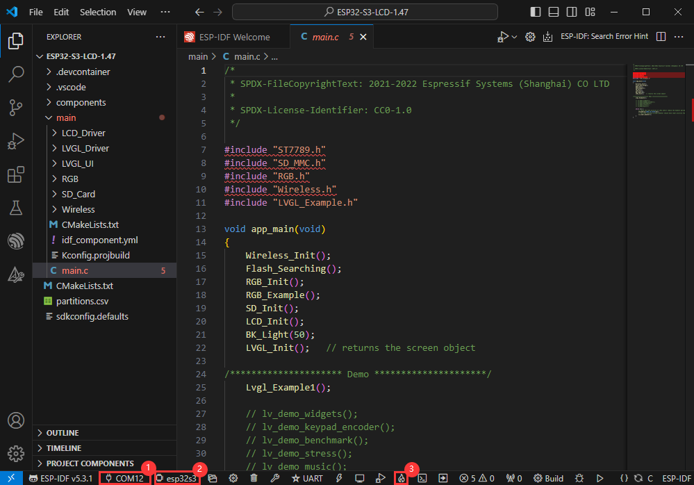
Other Status Bar Functions
①.ESP-IDF Development Environment Version Manager, when our project requires differentiation of development environment versions, it can be managed by installing different versions of ESP-IDF. When the project uses a specific version, it can be switched to by utilizing it
②.Device flashing COM port, select to flash the compiled program into the chip
③.Select set-target chip model, select the corresponding chip model, for example, ESP32-P4-NANO needs to choose esp32p4 as the target chip
④.menuconfig, click it to Modify sdkconfig configuration file Project configuration details
⑤.fullclean button, when the project compilation error or other operations pollute the compiled content, you can clean up all the compiled content by clicking it
⑥.Build project, when a project satisfies the build, click this button to compile
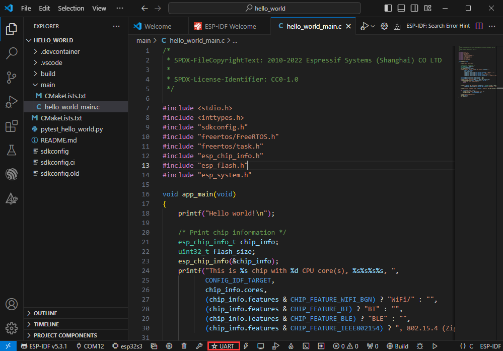
⑦.Current download mode, the default is UART
⑧.flash button, when a project build is completed, select the COM port of the corresponding development board, and click this button to flash the compiled firmware to the chip
⑨.monitor enable flashing port monitoring, when a project passes through Build --> Flash, click this button to view the log of output from flashing port and debugging port, so as to observe whether the application works normally
⑩.Debug
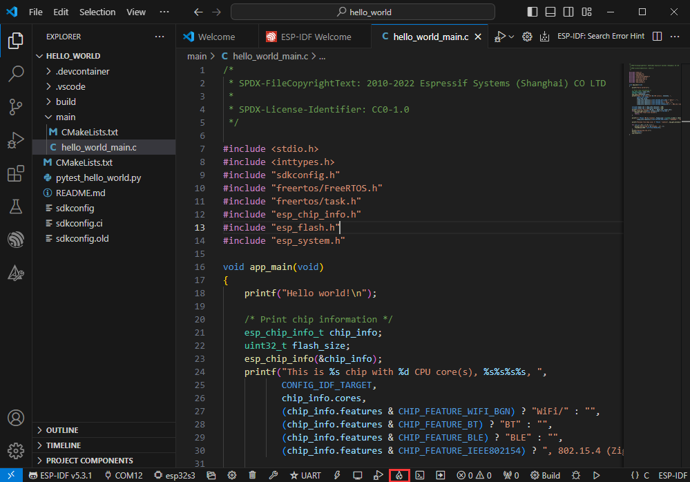
⑪.Build Flash Monitor one-click button, which is used to continuously execute Build --> Flash --> Monitor, often referred to as "little flame"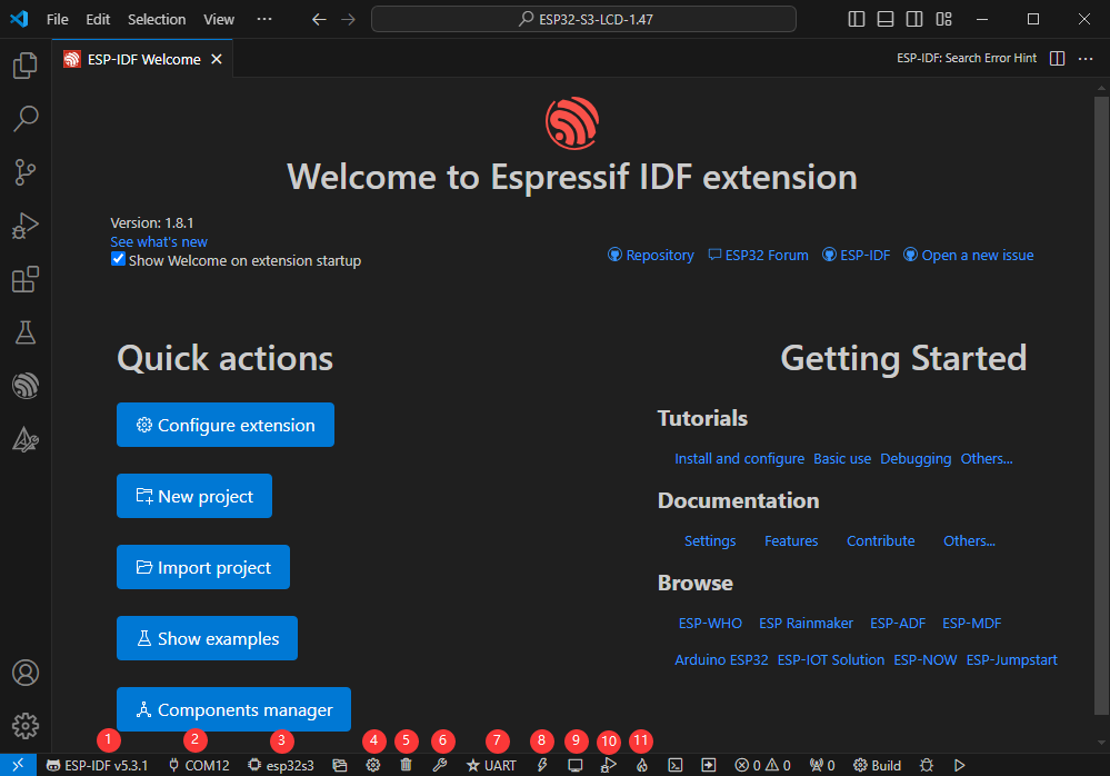
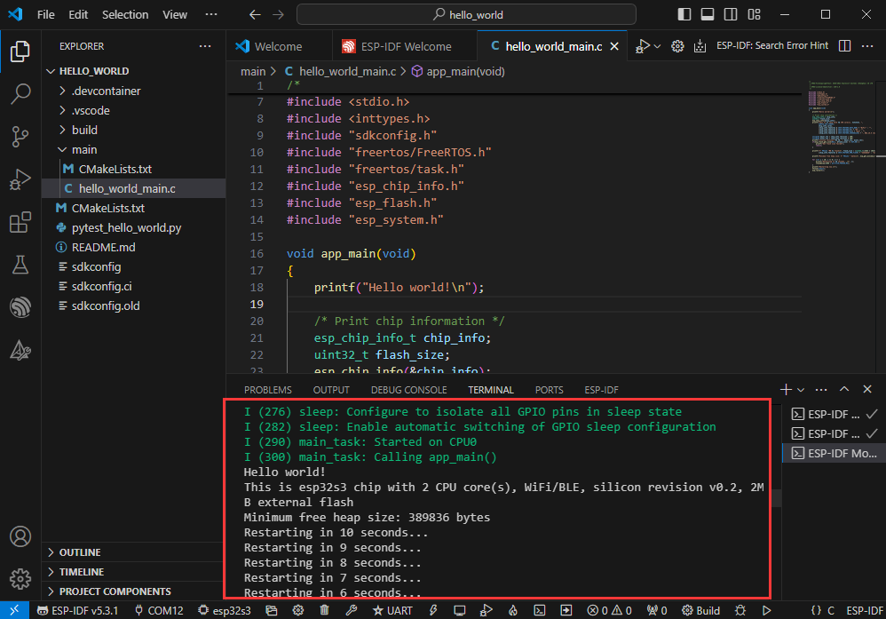
Compile, Flash and Serial Port Monitor
- Click on the all-in-one button we described before to compile, flash and open the serial port monitor
- It may take a long time to compile especially for the first time
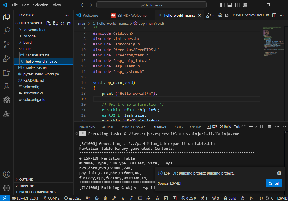
- During this process, the ESP-IDF may take up a lot of CPU resources, so it may cause the system to lag
- If it is the first time to flash the program for a new project, you will need to select the download method, and select UART
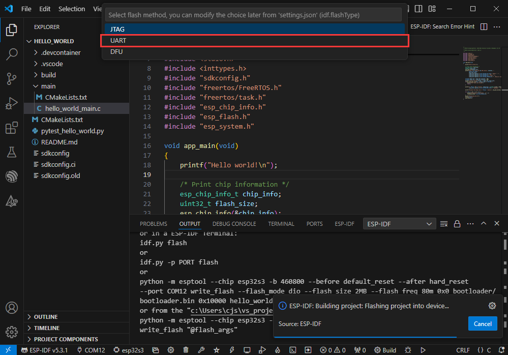
- This can also be changed later in the Download methods section (click on it to pop up the options)
- As it comes with the onboard automatic download circuit, it can be downloaded automatically without manual operation
- After successful download, it will automatically enter the serial monitor, you can see the chip output the corresponding information and be prompted to restart after 10S
Use the IDF Demos
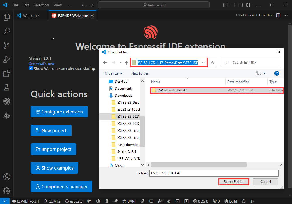
Open In the Software
- Open VScode software and select the folder to open the demo
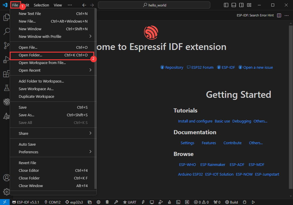
- Select the provided ESP-IDF example and click to select the file (located in the /Demo/ESP-IDF path under demo)
Open from Outside the Software
- Select the project directory correctly and open the project, otherwise it will affect the compilation and flashing of subsequent programs
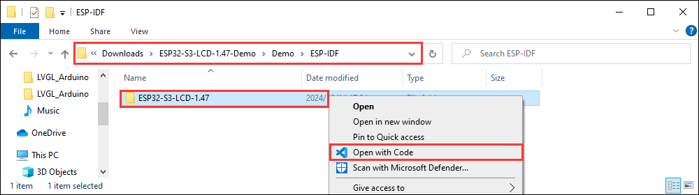
- After connecting the device, select the COM port and model, click below to compile and flash to achieve program control
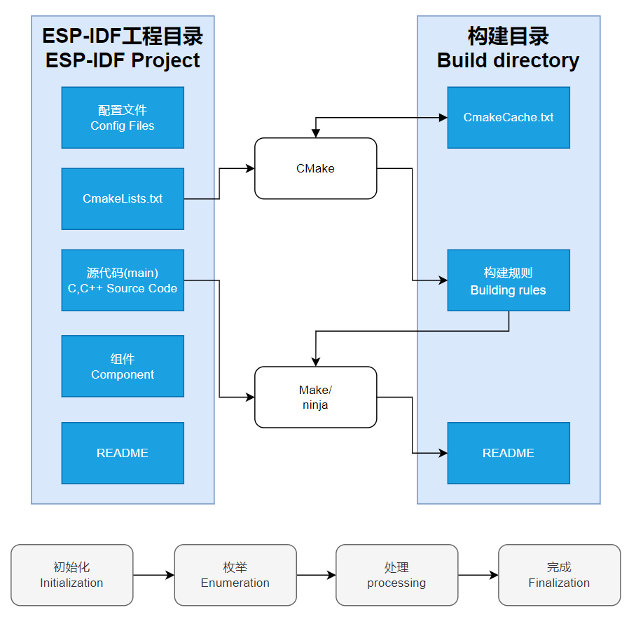
ESP-IDF Project Details
- Component: The components in ESP-IDF are the basic modules for building applications, each component is usually a relatively independent code base or library, which can implement specific functions or services, and can be reused by applications or other components, similar to the definition of libraries in Python development.
- Component reference: The import of libraries in the Python development environment only requires to "import library name or path", while ESP-IDF is based on the C language, and the importing of libraries is configured and defined through
CMakeLists.txt. - The purpose of CmakeLists.txt: When compiling ESP-IDF, the build tool
CMakefirst reads the content of the top-levelCMakeLists.txtin the project directory to read the build rules and identify the content to be compiled. When the required components and demos are imported into theCMakeLists.txt, the compilation toolCMakewill import each content that needs to be compiled according to the index. The compilation process is as follows:
- Component reference: The import of libraries in the Python development environment only requires to "import library name or path", while ESP-IDF is based on the C language, and the importing of libraries is configured and defined through
Demo

| Demo | Basic Description |
|---|---|
| 01_factory | Comprehensive demo |
| 02_lvgl_example_v8 | lvgl v8 demos |
| 03_lvgl_example_v9 | lvgl v9 demos |
| 04_qmi8658_example | Print IMU data through serial port |
| 05_pcf85063_example | Print RTC data through serial port |
| 06_lvgl_image_v8 | Display images using lvgl v8 version |
| 07_lvgl_image_v9 | Display images using lvgl v9 version |
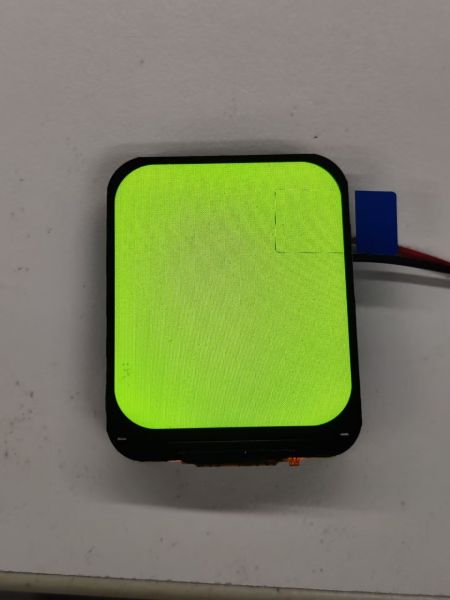
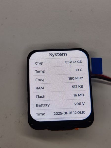
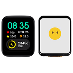
01_factory
【Demo description】
This is a comprehensive demo of ESP32-C6-LCD-1.69, which is also the default demo flashed at factory.
【Result demonstration】
- Hold down the BOOT button without releasing it, and the speaker will play back the sound collected by the microphone in real time.
- Short press the BOOT button and release it, the interface switches.
02_lvgl_example_v8
【Demo description】
This demo shows that ESP32-C6-LCD-1.69 runs lvgl v8 version demo.
【Result demonstration】
03_lvgl_example_v9
【Demo description】
This demo shows that ESP32-C6-LCD-1.69 runs lvgl v8 version demo.
【Result demonstration】
04_qmi8658_example
【Demo description】
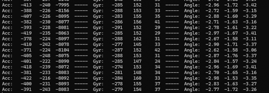
This demo demonstrates that ESP32-C6-LCD-1.69 drives QMI8658, obtains and prints Accel, Gyro, and Angle.
【Code analysis】
- Initialize and start the test program
    i2c_master_bus_handle_t i2c_bus_handle;
    bsp_pwr_init();
    i2c_bus_handle = bsp_i2c_init(); //I2C initialization
    bsp_qmi8658_init(i2c_bus_handle); // QMI8658 initialization
    bsp_qmi8658_test(); // QMI8658 test
【Result demonstration】
- Nothing will be shown on the screen
- Open the serial port monitor
05_pcf85063_example
【Demo description】
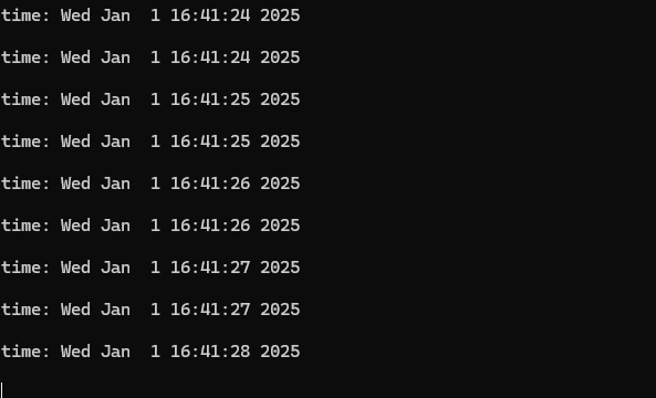
This demo demonstrates that ESP32-C6-LCD-1.69 drives PCF85063, sets the time, date, and obtains the time.
【Code analysis】
- Initialize and start the test program
    i2c_master_bus_handle_t i2c_bus_handle;
    bsp_pwr_init();
    i2c_bus_handle = bsp_i2c_init();   //I2C initialization
    bsp_pcf85063_init(i2c_bus_handle); // QMI8658 initialization
    bsp_pcf85063_test();               // QMI8658 test
【Result demonstration】
- Nothing will be shown on the screen
- Open the serial port monitor
06_lvgl_image_v8
【Demo description】
This demo shows that ESP32-C6-LCD-1.69 runs lvgl v8 version and displays pictures.
【Hardware connection】
- Connect the board to the computer
【Preparation】
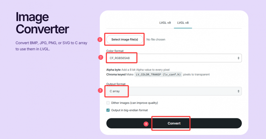
- Open lvgl Image Converter website
- Import the image images/image_1.jpg and convert it, the image_1.c file will be generated
- Copy image_1.c to the main folder
- Add "image_1.c" to the CMakeLists.txt in the main folder
idf_component_register(SRCS "main.cpp" "image_1.c"
                    INCLUDE_DIRS ".")
- Add the following code to main.c to declare the image
LV_IMG_DECLARE(image_1);
- Set the image to be displayed
lv_img_set_src(img, &image_1);
【Result demonstration】

07_lvgl_image_v9
【Demo description】
This demo shows that ESP32-C6-LCD-1.69 runs lvgl v8 version and displays pictures.
【Hardware connection】
- Connect the board to the computer
【Preparation】
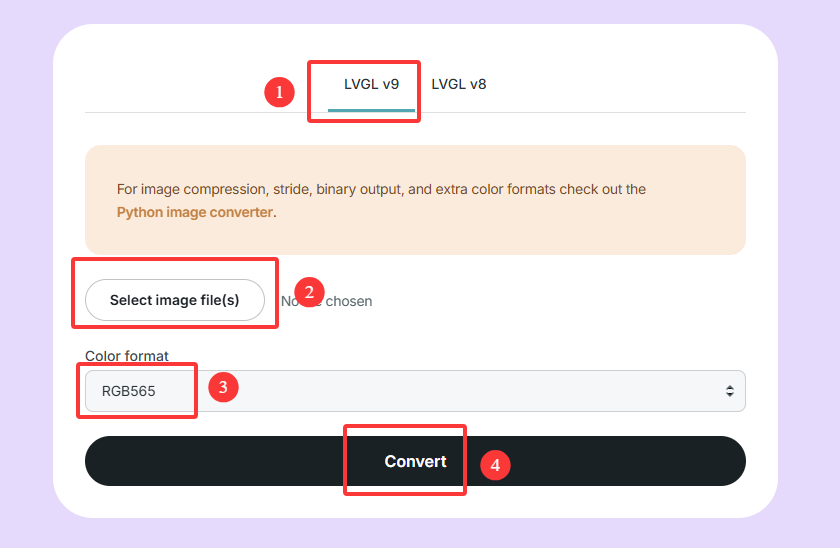
- Open lvgl Image Converter website
- Import the image images/image_1.jpg and convert it, the image_1.c file will be generated
- Copy image_1.c to the main folder
- Add "image_1.c" to the CMakeLists.txt in the main folder
idf_component_register(SRCS "main.cpp" "image_1.c"
                    INCLUDE_DIRS ".")
- Add the following code to main.c to declare the image
LV_IMAGE_DECLARE(image_1);
- Set the image to be displayed
lv_image_set_src(img, &image_1);
【Result demonstration】
Flash Firmware Flashing and Erasing
- The current demo provides test firmware, which can be used to test whether the onboard device functions properly by directly flashing the test firmware
- bin file path:
..\ESP32-C6-LCD-1.69-Demo\Firmware
Resources
Schematic Diagram
Demo
Datasheets
ESP32-C6
Other Components
Softwares
- Zimo221 Chinese character conversion software
- Image2Lcd image bitmap conversion software
- flash_download_tool_3.9.7
Other Resource Links
- Image bitmap conversion tutorial
- Font library conversion tutorial
- MicroPython official documentation
- ESP32 Arduino Core's documentation
- arduino-esp32
- ESP-IDF
FAQ
Question: Why does the flashing fail?
1. When the serial port is occupied, the flashing will fail. Close the serial port monitor and try to flash again
2. When the ESP32 program crashes, the flashing will fail, and the development module needs to be completely powered off, hold down BOOT and power it on again to enter the strong download mode and then flash it. It will not automatically exit the download mode after flashing, so you need to power off and restart again
Question: How to check the COM port I use?
Windows system:
①View through Device Manager: Press the Windows + R keys to open the "Run" dialog box; Input devmgmt.msc and press Enter to open Device Manager; Expand the "Port (COM and LPT)" section, here it will list all the COM ports and their current status.
②Use the command prompt to view: Open the Command Prompt (CMD); enter the mode command, which will display status information for all COM ports.
③Check hardware connections: If you have already connected external devices to the COM port, the device usually occupies a port number, which can be determined by checking the connected hardware.
Linux system:
①Use the dmesg command to view: Open the terminal.
①Use the ls command to view: Enter ls /dev/ttyS* or ls /dev/ttyUSB* to list all serial port devices.
③Use the setserial command to view: Enter setserial -g /dev/ttyS* to view the configuration information of all serial port devices.
Question: What is the spacing between the 11 tp points on the back of ESP32-C6-LCD-1.69?
- 2.15mm
Question: Why is there no output after successfully flashing the code with no issues?
- Check the schematic diagram for different development boards with Type-C interfaces, and handle the output accordingly:
- For development boards with direct USB output, printf function is supported for printing output. If you want to support output via the Serial function, you will need to enable the USB CDC On Boot feature or declare HWCDC.
- For development boards with UART to USB conversion, both printf and Serial functions are supported for printing output, and there is no need to enable USB CDC On Boot.
Support
Monday-Friday (9:30-6:30) Saturday (9:30-5:30)
Email: services01@spotpear.com
[Tutorial Navigation]
- Overview
- Usage Instructions
- Working with Arduino
- Working with ESP-IDF
- Environment Setup
- Run the First ESP-IDF Demo
- New Project
- Create Demo
- Modify COM Port
- Modify Driver Object
- Other Status Bar Functions
- Compile, Flash and Serial Port Monitor
- Use the IDF Demos
- Demo
- Flash Firmware Flashing and Erasing
- Resources
- FAQ
- Question: Why does the flashing fail?
- Question: How to check the COM port I use?
- Question: What is the spacing between the 11 tp points on the back of ESP32-C6-LCD-1.69?
- Question: Why is there no output after successfully flashing the code with no issues?
- Support