- sales/support
Google Chat:---
- sales
+86-0755-88291180
- sales01
sales@spotpear.com
- sales02
dragon_manager@163.com
- support
tech-support@spotpear.com
- CEO-Complaints
zhoujie@spotpear.com
- Only Tech-Support
WhatsApp:13246739196
- Purchase/Shipping/Refund
WhatsApp:13424403025
- HOME
- >
- ARTICLES
- >
- Common Moudle
- >
- UART Module
USB TO RS485 (E) User Guide
Features
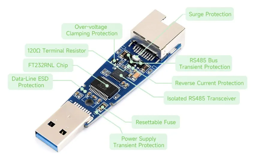
- Supports bidirectional communication between USB and a single RS485 channel, with hardware automatically controlling data transmit/receive direction
- Uses the FT232RNL USB-to-UART chip
- Isolated RS485 transceiver integrates signal isolation and isolated power supply
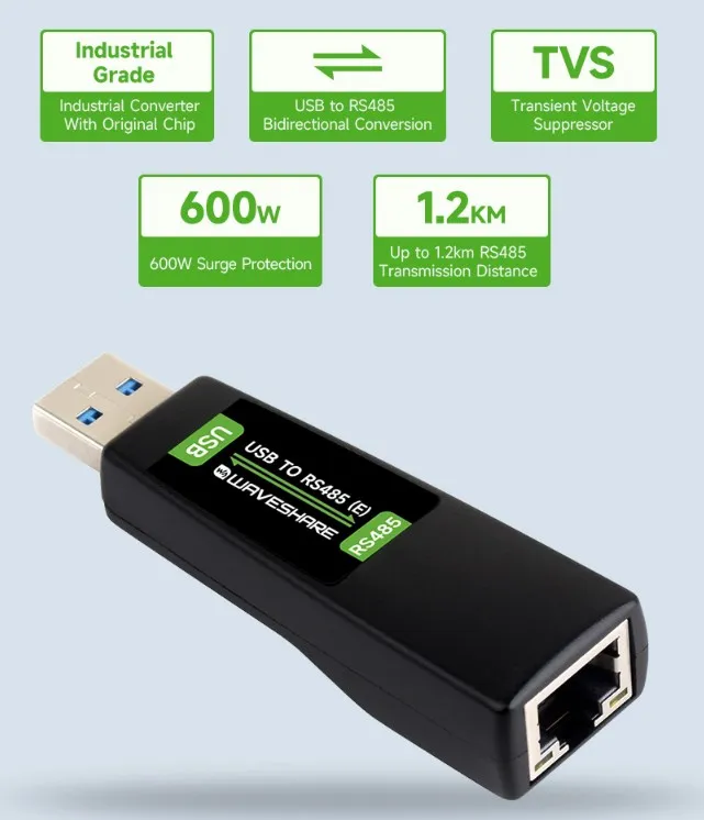
- Transient surge and ESD protection circuits on both USB and RS485 sides, rated for 600 W lightning surge protection
- Onboard TVS, ESD protection devices, resettable fuse, and protection diodes
- Onboard fixed 120 Ω termination resistor
- RJ45 interface provides 5 V auxiliary power output, maximum output current 100 mA
- Equipped with TXD and RXD status indicators
- Supports Windows, macOS, Linux, Android, and WinCE
Product Specifications
| Parameter | Description |
|---|---|
| Product Type | Industrial-grade isolated USB-to-RJ45 single-channel RS485 converter |
| Communication Chip | FT232RNL |
| Communication Rate | 300 bps - 512000 bps |
| Host Interface | USB-A, 5 V operating level |
| Device Interface | RJ45 female socket, single-channel RS485, T568B pinout |
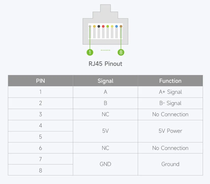
| RS485 Pinout | 1=A, 2=B, 3=NC, 4=5 V, 5=5 V, 6=NC, 7=GND, 8=GND |
| Auxiliary Power Output | 5 V, maximum output current 100 mA |
| Direction Control | Hardware automatically determines and controls data transmission direction |
| RS485 Nodes | Point-to-multipoint communication, up to 32 nodes; a repeater is recommended when exceeding 16 nodes |
| RS485 Transmission Distance | Approximately 1200 m (at low baud rates and with ideal cable conditions) |
| USB Transmission Distance | Approximately 5 m |
| Termination Matching | Onboard fixed 120 Ω termination resistor |
| Isolation Method | Isolated RS485 transceiver with integrated signal isolation and isolated power supply |
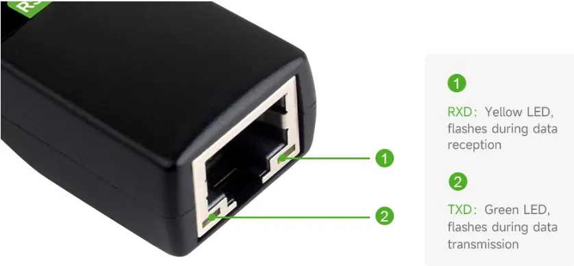
| Indicators | TXD transmit indicator (green), RXD receive indicator (yellow) |
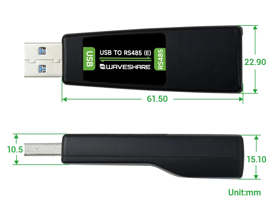
| Enclosure Size | Approx. 61.5 mm × 22.9 mm × 15.1 mm, excluding USB-A plug |
| Operating Temperature | -40°C - 85°C |
| Operating Humidity | 5% RH - 95% RH |
| Operating Systems | Windows 11 / 10 / 8.1 / 8 / 7 / XP, macOS, Linux, Android, WinCE |
Appearance and Connection
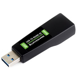
The product features a black straight-plug enclosure with a USB-A plug on one end and an RJ45 female socket on the other. The RXD and TXD indicators are located next to the RJ45 socket. Connect the USB-A end to the host, and connect the RJ45 female socket to a cable with an RJ45 male plug; the other end of the cable should be wired according to the target RS485 device's pinout.
The RJ45 form factor does not imply Ethernet protocol. A standard straight-through patch cable only ensures pin-to-pin continuity — it does not guarantee that the signal definitions on the peer device match those of this product.
RJ45 Pinout
RJ45 pinout reference
The table follows RJ45 contact numbering. When inspecting the socket or making a cable, always refer to the pin markings on the connector and the crimped plug — do not rely solely on visual orientation.
This interface does not support Ethernet. Do not connect it to a switch, router, or any Ethernet port. If the peer device does not use the power pins, leave pins 4 and 5 disconnected. When using the 5 V auxiliary power, the load current must not exceed 100 mA.
Indicator Descriptions
| LED Indicator | Status Description |
|---|---|
| RXD | Yellow LED flashes when data is returned from the RS485 device side |
| TXD | Green LED flashes when data is being sent from the USB side |
Isolation and Protection
The product uses an RS485 transceiver that integrates signal isolation and an isolated power supply. The USB side and RS485 side are equipped with TVS, ESD protection devices, a self-recovery fuse, and protection diodes to suppress the effects of transient surges, electrostatic discharge, overcurrent, and overvoltage on the interfaces. Isolation and protection circuits do not replace on-site grounding, shielding, or lightning protection measures.
Product Dimensions
The 61.5 mm dimension shown is the enclosure length, excluding the USB-A plug.
User Guide
Driver Installation
The USB TO RS485 (E) uses the FT232RNL chip. After the operating system recognizes the device, it will be used as a virtual serial port. If the system does not generate a serial device, install the FTDI Virtual COM Port (VCP) driver for your operating system.
The images below show the FTDI driver installation interface on Windows. The interface may vary depending on the driver version or operating system version.
Windows Manual Installation
Connect the converter to your computer. If the serial device in Device Manager shows a yellow exclamation mark, the driver is not properly installed.
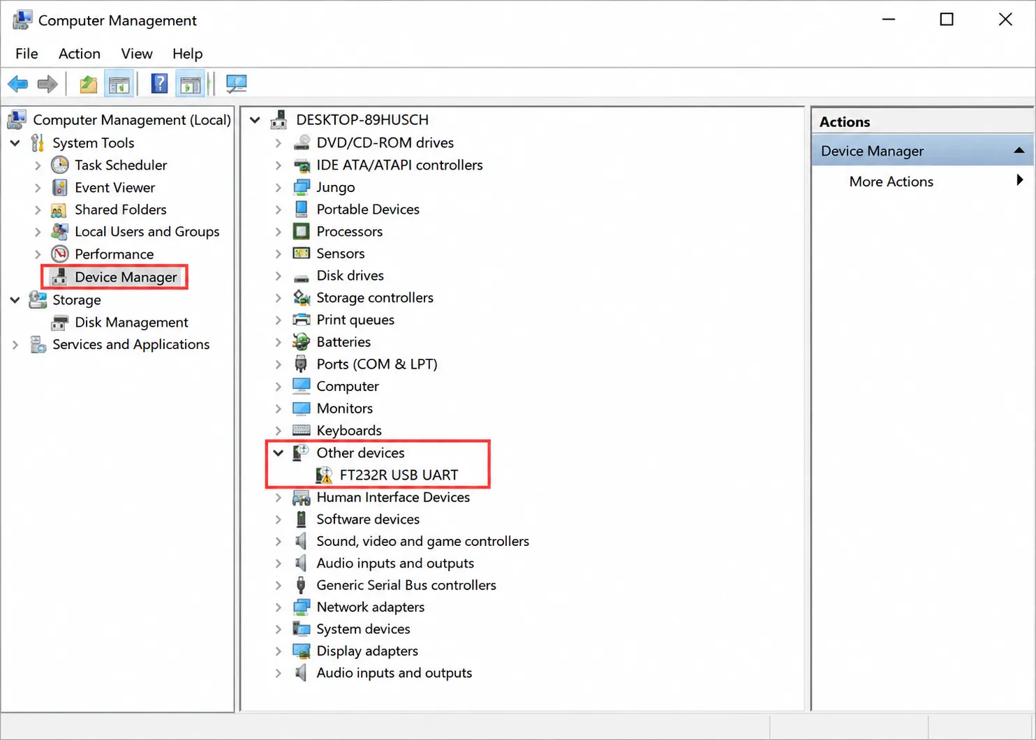
Download the driver for your operating system from the FTDI VCP driver page. Run the Windows installer and extract the installation files as prompted.
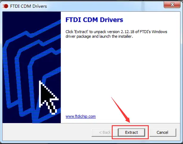
Read the license agreement, accept the terms, and proceed with the installation.
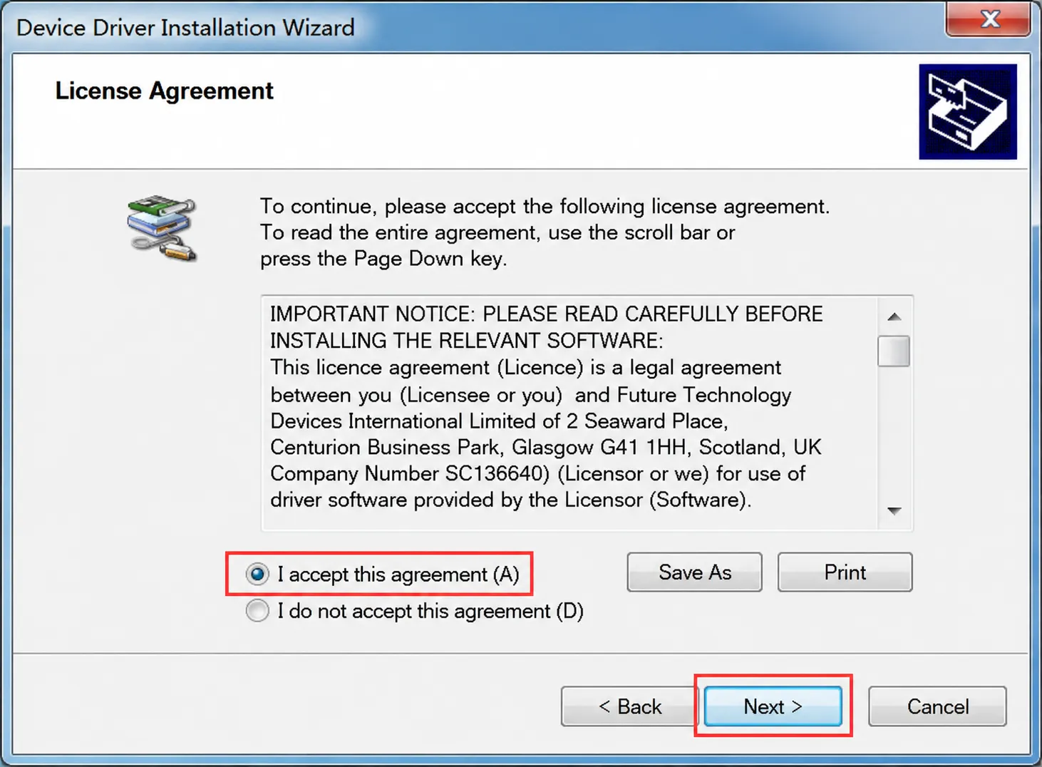
After installation is complete, unplug and reconnect the converter. Confirm the COM port number under "Device Manager" > "Ports (COM & LPT)".
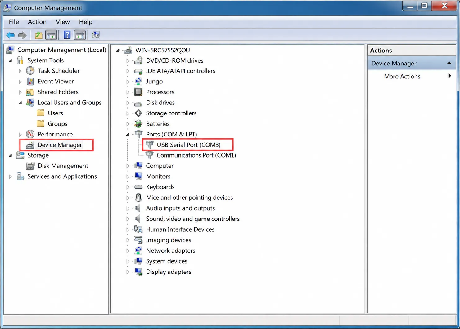
On Linux and macOS, confirm the device name in the system serial device list.
RJ45 Socket Wiring
The RJ45 socket uses T568B pinout, but carries RS485 signals and auxiliary power — not Ethernet data.
RJ45 pinout reference
Different devices may have different RJ45 RS485 pin assignments. A standard straight-through cable only ensures pin-to-pin continuity; it does not guarantee signal compatibility with the peer device. Always consult the peer device's manual before connecting. Do not connect to an Ethernet port. If the peer device does not use the power pins, leave pins 4 and 5 disconnected. When using the 5 V auxiliary power, the load current must not exceed 100 mA.
Connecting to RS485 Devices
- Insert a T568B straight-through cable with an RJ45 male plug into the converter's RJ45 socket.
- At the other end of the cable, use an RJ45 adapter board or make a custom wiring harness according to the target device's interface definition.
- Connect A and B, and decide whether to connect GND based on your field grounding scheme.
- Verify the contact numbering and signal definitions at both ends of the cable before connecting the USB end.
| USB TO RS485 (E) | Target RS485 Device |
|---|---|
| A | A / D+ / 485+ |
| B | B / D- / 485- |
| GND | GND, connect according to site grounding scheme |
Different manufacturers may label RS485 A and B oppositely. If communication fails after correct wiring, verify polarity against the target device's manual.
Termination
The E model has a fixed 120 Ω termination resistor onboard, which cannot be disabled via switch. Termination resistors should generally be placed only at the two ends of an RS485 main line. Therefore, place this converter at a bus endpoint — do not use it as a middle node.
RS485 Communication Test
- Connect the target RS485 device following RJ45 Socket Wiring and confirm A, B, and GND definitions.
- Connect the converter to the host and confirm the virtual serial port in the system.
- Open a serial debug tool, select the corresponding COM port, and set the baud rate, data bits, parity, and stop bits to match the target device.
- Send test data and check the receive window.
- If communication fails, check A/B polarity, serial parameters, termination, reference ground, and cable connections in sequence.
The supported communication rate range is 300 bps to 512000 bps. The actual rate must match the target device's settings.
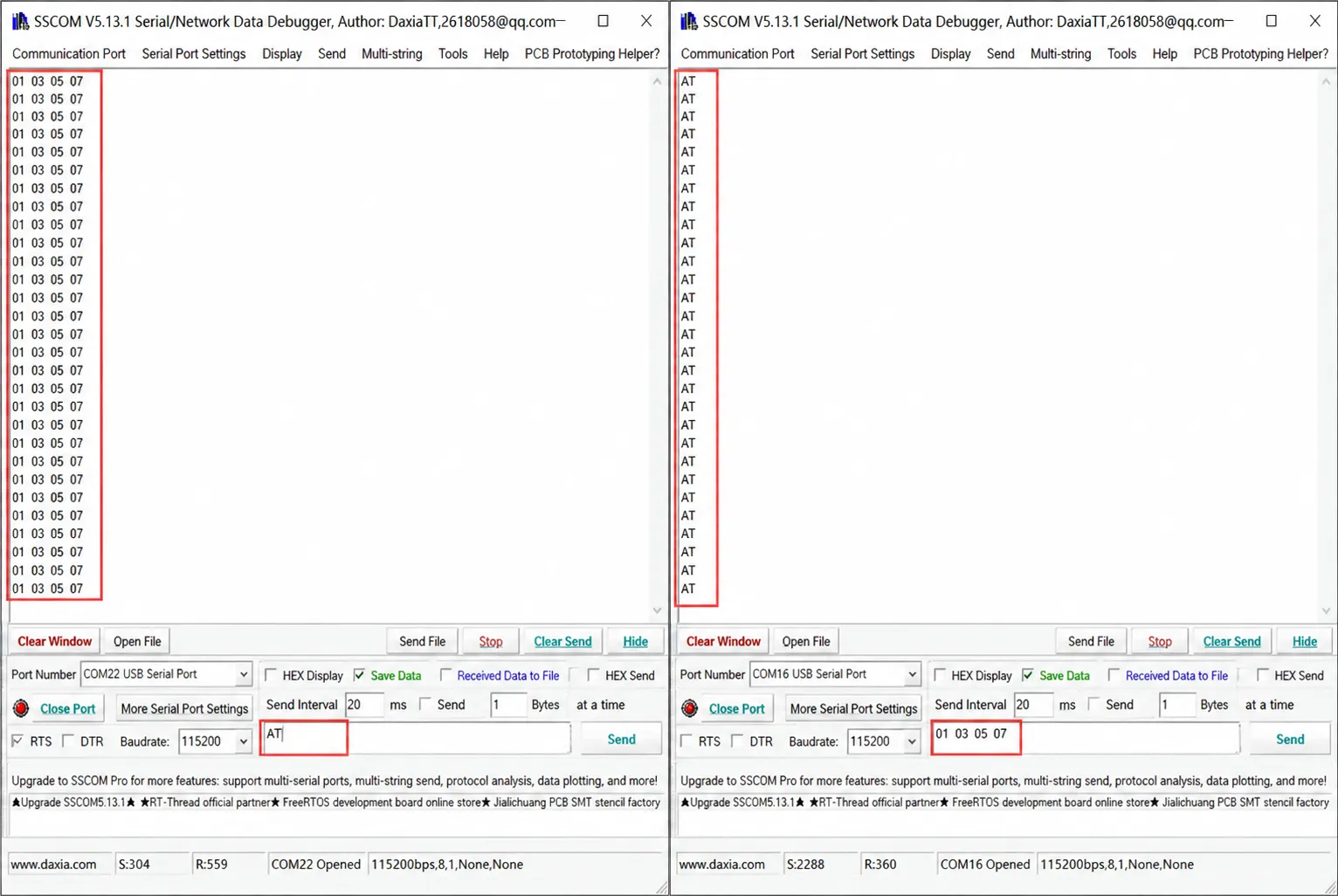
Modbus RTU Device Communication
The USB TO RS485 (E) performs physical-layer conversion between USB and RS485. It does not include a built-in Modbus protocol stack. When connecting to Modbus RTU devices, the host software or master application must generate and parse Modbus frames.
- Confirm the slave address, baud rate, parity, data bits, and stop bits.
- Use a Modbus debugging tool or custom program to open the serial port corresponding to the converter.
- Set the function code, register address, and data format according to the slave device protocol manual.
- Send requests and check responses and serial error messages.
Wiring Notes
- RS485 buses should use twisted-pair cables; shielded twisted-pair cables are recommended for long-distance or high-interference environments.
- For multi-node communication, use a bus topology and avoid long star branches.
- Isolation circuits do not replace on-site grounding, shielding, or lightning protection designs.
- When routing cables near high-voltage lines, variable-frequency drives, or motors, maintain appropriate spacing, shielding, and grounding per site specifications.