




- sales/support
Google Chat:---
- sales
+86-0755-88291180
- sales01
sales@spotpear.com
- sales02
dragon_manager@163.com
- support
tech-support@spotpear.com
- CEO-Complaints
zhoujie@spotpear.com
- Only Tech-Support
WhatsApp:13246739196
- Purchase/Shipping/Refund
WhatsApp:13424403025
- HOME
- >
- ARTICLES
- >
- Common Moudle
- >
- GSM-GPS
LG290P GNSS RTK Module User Guide
Overview
Introduction
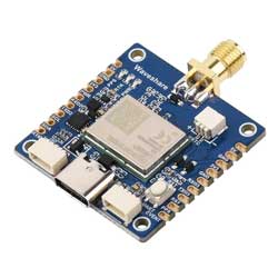
The LG290P GNSS RTK Module is a quad-band, multi-constellation GNSS RTK module that supports the L1, L2, L5 and E6 frequency bands, compatible with GPS, BDS, GLONASS, Galileo, QZSS and NavIC satellite systems. Based on a high-performance GNSS SoC architecture, it integrates professional-grade interference detection and cancellation algorithm to effectively mitigate multiple narrow-band interferences, maintaining high sensitivity and strong anti-jamming performance even in complex electromagnetic environments. Through multi-frequency observations and RTK real-time differential algorithm, it significantly reduces multipath errors and enables centimetre-level high-precision positioning. With its small size and castellated holes design, this module boasts a rich set of interfaces, and is easy to integrate, making it an ideal choice for high-precision navigation applications such as intelligent robots, precision agriculture, mining, surveying and mapping, and autonomous driving.
Features
- Multi-constellation GNSS support including GPS / GLONASS / Galileo / BDS / QZSS / NavIC
- Quad-band reception (L1 + L2 + L5 + E6) for higher positioning accuracy and stronger anti-interference performance
- Centimeter-level RTK real-time differential positioning, with real-time status reporting of differential positioning
- Castellated holes with immersion gold design, small size, easy to integrate into the device by soldering directly or inserting via the pin header
- Onboard Type-C port supporting USB-UART communication and module power supply, enabling easy development and debugging
- Onboard 2PIN JST connector for connecting an RTC backup battery, effectively reducing Time to First Fix (TTFF)
- Onboard 3 x LED indicators for module operating status
- Comes with online development resources and manual (Demos for Raspberry Pi / Raspberry Pi Pico / Jetson Orin / ESP32 / Arduino)
Specifications
| Model | LG290P GNSS RTK Module | LC29H(AA) GPS HAT | LC29H(DA) GPS/RTK HAT | LC29H(BS) GPS/RTK HAT | ZED-F9P GPS-RTK HAT | |
|---|---|---|---|---|---|---|
| Frequency Band | GPS: L1 C/A, L1C*, L5, L2C GLONASS: L1, L2 | GPS/QZSS: L1C/A, L5 BDS: B1I, B2a | GPS/QZSS: L1C/A, L2C BDS: B1I, B2I | |||
| Number of Concurrent GNSS | 5 + QZSS | GPS/QZSS + BDS + Galileo + GLONASS | ||||
| SBAS | WAAS, EGNOS, BDSBAS, MSAS, GAGAN and SDCM | WAAS, EGNOS, MSAS and GAGAN | - | WAAS, EGNOS, MSAS and GAGAN | ||
| RTK Function | RTK Rover and Base | - | RTK Rover | RTK Base | RTK Rover and Base | |
| Positioning Accuracy | PVT | 0.7m CEP | 1m CEP | - | 1.5m CEP | |
| RTK | 0.8cm + 1ppm CEP | - | 0.01m + 1ppm CEP | - | 0.01m + 1ppm CEP | |
| Navigation Update Rate | PVT | Default: 10Hz Max.: 20Hz | 1~10Hz | - | 1~10Hz | |
| RTK | - | 1Hz | - | 1~8Hz | ||
| RAW | 1Hz | 1~20Hz | ||||
| RTK Convergence Time (Open Outdoor Test) | <5s | - | <10s | - | <10s | |
| Time to First Fix (AGNSS Off) | Cold Start | 28s | 26s | - | 24s | |
| Hot Start | 1.7s | 1s | - | 2s | ||
| Warm start | 28s | 16s | - | 2s | ||
| Time to First Fix (EASY on) | - | 2s | - | |||
| Time to First Fix (AGNSS On) | Cold Start | - | 5s | - | TBD | |
| Hot Start | - | 5s | - | TBD | ||
| Warm Start | - | 5s | - | TBD | ||
| Sensitivity | Tracking and Navigating | -160dBm | -165dBm | -167dBm | ||
| Re-acquisition | -155dBm | -159dBm | -157dBm | -159dBm | -160dBm | |
| Cold Start | -146dBm | -147dBm | -145dBm | -147dBm | -148dBm | |
| Velocity Accuracy | 0.03m/s | 0.2m/s | - | 0.05m/s | ||
| PPS Accuracy | 5ns | 20ns | - | 30ns | ||
| Dynamic Performance | Acceleration (Max): 4g | |||||
| Altitude (Max): 10000m | Altitude (Max): 50000m | |||||
| Velocity (Max): 490m/s | Velocity (Max): 500m/s | |||||
| Communication Interface | USB, UART(4800~921600bps, 460800bps by default) | UART(9600~3000000bps, 115200bps by default), I2C(Max 400KHz) | USB, UART(4800~921600bps, 9600bps by default), I2C(Max 400KHz), SPI(5MHz) | |||
| Communication Protocol | NMEA 0183/RTCM 3.x | NMEA 0183 V4.10, RTCM 3.x | NMEA 0183 V4.10, UBX, RTCM 3.3 | |||
| Power Supply | 5V | |||||
| Overall Current | <100mA@5V (Continue mode) | <40mA@5V (Continue mode) | <120mA@5V (Continue mode) | |||
| Operating Temperature | -40~85℃ | |||||
| Dimensions | 33 × 33 (mm) | 65 × 30.5 (mm) | ||||
Resources & Interfaces
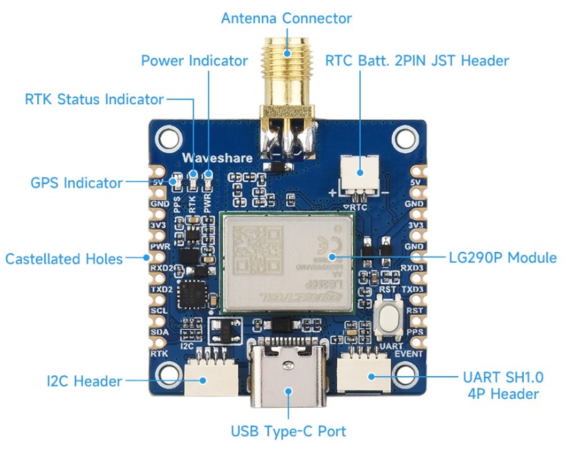
| Left Pins | Function | Right Pins | Function |
|---|---|---|---|
| 5V | 5V power supply positive | 5V | 5V power supply positive |
| GND | Power ground | GND | Power ground |
| 3V3 | 3.3V power supply positive | 3V3 | 3.3V power supply positive |
| PWR | Module power control pin | GND | Power ground |
| RXD2 | UART2 RX, for RTCM differential input | RXD3 | UART3 RX, for channel debugging |
| TXD2 | UART2 TX, outputs base-station differential data | TXD3 | UART3 TX, supports NMEA output |
| SCL | I2C clock (reserved) | RST | Module reset pin |
| SDA | I2C data (reserved) | PPS | 1PPS pulse output |
| RTK | RTK status output | EVENT | Event output signal, used for position / time-tag triggers |
Dimensions
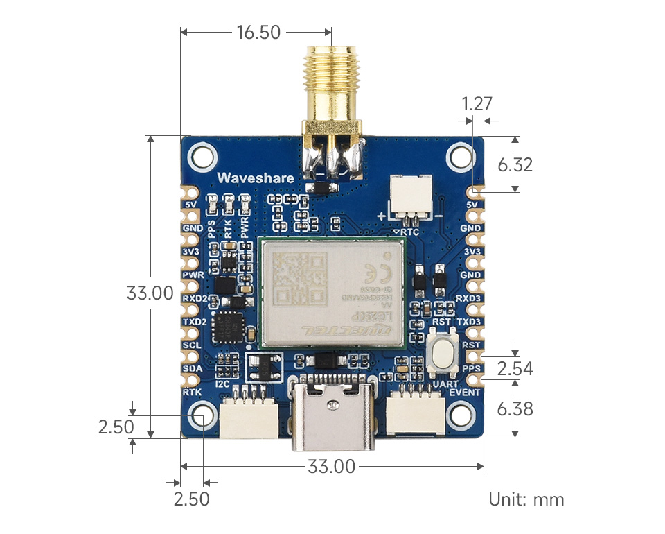
Positioning Principle
What is GNSS?
The full name of GNSS is Global Navigation Satellite System, which refers to multiple satellite systems. Currently, there are BDS (China), GLONASS (Russia), GPS (United States), Galileo (Europe), QZSS (Japan), IRNSS (India) navigation satellite systems in the world. The characteristics of GNSS are as follows:
- The GPS system is a widely used and relatively mature satellite positioning technology at the current stage. It has successively developed L1C/A, L2C, L5 frequency band signals to improve positioning accuracy.
- Multi-system and multi-band GNSS modules can capture signals from different satellite systems, greatly increasing the number of effective satellites and improving positioning accuracy and stability.
- The signals received by the GNSS module include reflection and refraction signals, which produce multi-path effects that affect the positioning accuracy. The multi-band and multi-constellation system technology can effectively suppress and weaken the atmospheric error and improve the positioning accuracy.
With the development of GNSS, various positioning technologies such as RTK, PPP-RTK, and multi-sensor fusion positioning DR (Dead Reckoning) have emerged, meeting differentiated high-precision positioning needs.
GPS Working Principle
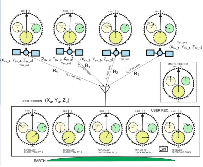
This section briefly describes the working principle of GPS receiver positioning, as shown in the figure below. Detailed descriptions are provided in 5 points.
- GPS satellites continuously send radio signals with their own time and position information in the air for GPS receivers (GNSS modules such as ZED-F9P).
- A pseudo-random code will be generated inside the satellite and the receiver. Once the two pseudo-random codes are synchronized, the receiver can measure the difference between the time the radio signal is transmitted and the time it arrives at the receiver (referred to as the time delay), and multiply the time delay by the speed of light to get the distance (pseudorange).
- The time of the GPS system is maintained by the rubidium atomic frequency standard of the atomic clocks on each satellite. These satellite clocks are generally accurate to within a few nanoseconds of Coordinated Universal Time (UTC), which is maintained by the Naval Observatory's "Master Clock", the stability of each master clock is several 10^(-13) seconds.
- Computers and navigation information generators on GPS satellites know precisely their orbital positions and system time, while a global network of monitoring stations keeps track of satellites' orbital positions and system time. The main control station at Schriever Air Force Base in Colorado, together with its operation and control section, input the orbital position and onboard clock correction data calculated on the basis of complex models into each GPS satellite at least once a day.
- To calculate the 3D position of the GPS receiver (GNSS module), the GPS receiver is required to receive signals from at least four satellites, and the 3D position is calculated according to the space triangle Pythagorean theorem and the quadratic linear equation.

What is RTK?
RTK (Real Time Kinematic), also known as carrier phase differential technology, is a GNSS positioning technology that supports centimeter-level positioning accuracy (referred to as RTK) and is a differential method for real-time processing of the carrier phase observations of two measuring stations. The working process of RTK is shown in the figure below. The DGPS corrections generated by the base station (GNSS receiver) are transmitted to the mobile station (GNSS receiver) in real-time through the mobile network for calculation and centimeter positioning.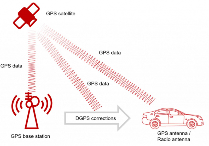
RTK Application
- Apply in various control surveys such as traditional geodetic surveys and engineering control surveys in triangulation and wire netting methods, and use RTK to measure the positioning accuracy in real-time to ensure observation quality and improve operational efficiency. Compared with non-real-time measurements such as normal GPS static surveys, fast static surveys, and pseudo-dynamic surveys, it must be retested when the accuracy does not meet the requirements. In addition, RTK is used in highway control measurement, electronic circuit control measurement, water conservancy engineering control measurement, and geodetic survey, which can reduce labor intensity, save costs, and complete control point measurement within minutes or even seconds.
- Topographic mapping: Using RTK only requires one person with the instrument to stay at the detail point for a second or two, and input the feature code at the same time. The accuracy of points and areas can be known in real-time through the handbook. After returning to the room, the professional software interface can output the required topographic map. In this way, RTK only requires one person to operate, and it does not require point-to-point vision, which greatly improves efficiency. With RTK and the electronic handbook, you can measure and design various topographic maps, such as general surveying, railway strip topographic maps, highway pipeline topographical maps, reservoir topographic maps, nautical ocean surveying, and so on with the depth sounder.
- Setting out is an application branch of measurement. When using RTK to set out, you only need to input the designed point coordinates into the electronic handbook with the GPS receiver on your back, and it will remind you to go to the position. It is not only fast and easy but also is high-accuracy and uniform as GPS is set out by coordinates directly. Hence, the efficiency of setting out in exterior operation is greatly improved, and only one person to operate.
Usage Guide
RTK Rover refers to the use of the LG290P module as a mobile station, connecting and receiving RTCM data streams from services like Qianxun Positioning (China mainland) or other reference base station service provider to achieve high-precision centimeter-level positioning.
RTK Base refers to using the LG290P as a base station to establish a CORS (Continuous Operational Reference System), providing RTCM data streams to other devices, thereby enabling real-time centimeter-level positioning for those devices.
Windows
This section is the introduction to quick setup and use of LG290P series modules using QGNSS software on Windows PCs. For detailed instructions on using QGNSS software, please refer to the Quectel_QGNSS_User_Guide_V3.2.pdf file from QGNSS_2.2.zip
Install CH343 Driver
Download and double-click to install CH343 Windows VCP driver
Implement RTK Mobile Station Positioning
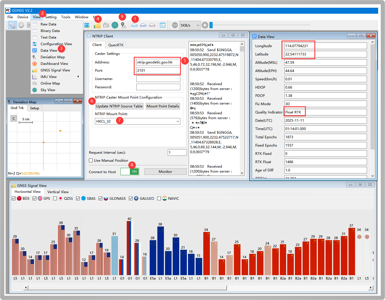
- Download and open QGSS tool, 1️⃣click NTRIP client, 2️⃣click view, ️3️⃣select Data View to open, 4️⃣open the satellite signal bar graph interface, 5️⃣configure the following Addressh and Port parameters to the corresponding location:
 Address:    ntrip.geodetic.gov.hk
 Port:                        2101
 Mount Point:               HKCL_32
 Username:                    Leave blank
 Password:                    Leave blank
6️⃣click Update NTRIP Source Table, 7️⃣ select HKCL_32 node, 8️⃣turn on ON, the button turns green, and the communication with the base station is successful. NTRIP Client prints the following information:
Received (14)bytes from server :
ICY 200 OK
Wait for 2-15 minutes until the latitude, longitude, and Float RTK prompts appear in the Data View window on the right to achieve RTK positioning, 9️⃣Open the deviation chart to see the positioning accuracy
RTK Base RTK Caster RTK Rover
- Before setting up the base station module, first understand that NTRIP (Networked Transport of RTCM via Internet) is an acronym for transmitting RTK differential data over the Internet. This allows for the expansion of RTK networks with an unlimited number of bases and mobile stations. A network with multiple NTRIP devices is called an NTRIP network. There are three roles in an NTRIP network: NTRIP Caster, which is a server responsible for receiving and sending GNSS differential data. It collects RTK correction data (i.e., RTCM data) from one or more base stations and distributes it to RTK mobile stations. Emlid Caster and rtk2go, etc., are cloud-based public Casters that can transmit RTCM data by uploading it to these relay stations, eliminating the cumbersome steps of setting up a Caster. Below, we will test by setting up the Emlid Caster public Caster as an example.
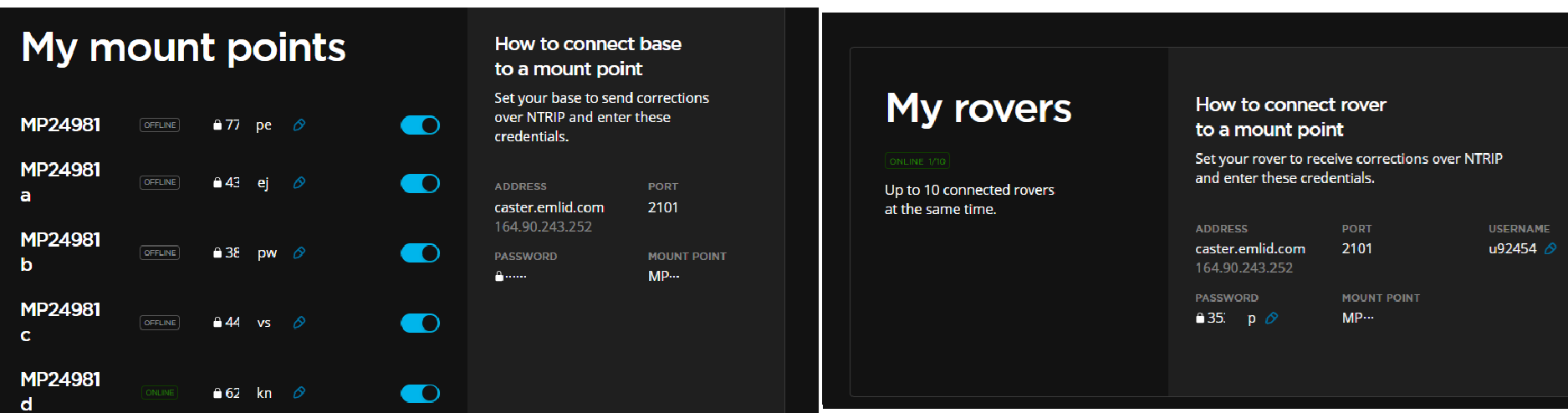 Configure the My mount points from the above image to the base station, and configure the My rovers parameters to the mobile station
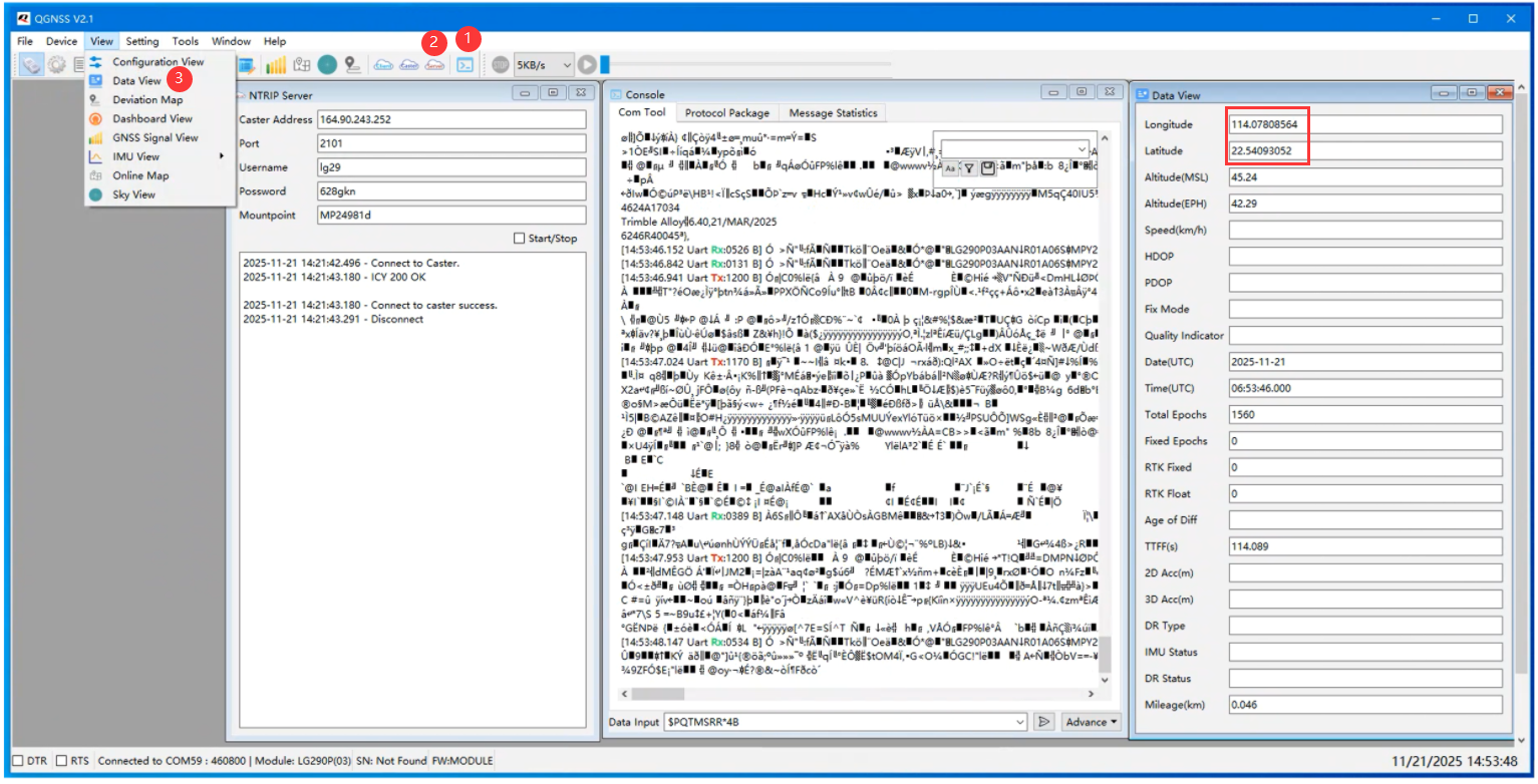
- Open the QGNSS tool, 2️⃣enter the parameters obtained from the Emlid Caster in the NTIRP Server window
 ADDRESS:              164.90.243.252
 PORT:                           2101
 MOUNT POINT:                MP24981d
 PASSWORD:                     62XXXX
- Then check "Start", and after successfully connecting to the server, print
Connect to caster success
ICY 200 OK;
#Configure module working mode to base station mode
$PQTMCFGRCVRMODE,W,2*29

#Command executed successfully
$PQTMCFGRCVRMODE,OK*64

#Save configuration
$PQTMSAVEPAR*5A

#Command executed successfully
$PQTMSAVEPAR,OK*72

#Restart the module (either by sending the relevant command or by pin reboot of the hardware RESET_N, using the command to restart here)
$PQTMSRR*4B

#Waiting for the module to power on
#Configure the base station Survey-in mode, with 60 positioning (convergence) times, and a 3D location accuracy threshold of 15.0 meters)
$PQTMCFGSVIN,W,1,60,15.0,0,0,0*3E

#Command executed successfully
$PQTMCFGSVIN,OK*70

#Configure PQTMSVINSTATUS through PQTMCFGMSGRATE to output once per positioning to view Survey-in status (this step is optional)
$PQTMCFGMSGRATE,W,PQTMSVINSTATUS,1,1*58

#Command executed successfully
$PQTMCFGMSGRATE,OK*29

#Save configuration
$PQTMSAVEPAR*5A

#Command executed successfully
$PQTMSAVEPAR,OK*72

#Restart the module (either by sending the relevant command or by pin reboot of the hardware RESET_N, using the command to restart here)
$PQTMSRR*4B

#Output the mean base station convergence ECEF coordinates via RTCM3-1005 (this statement is output by default when the module is in base station mode)
D3 00 13 3E D1 22 03 3B 54 97 DA 6F 8C 99 B2 AF 40 06 4C FC 1A 4B 1E 7D F1

#View the convergence mean of the ECEF coordinates of the base station from the start of the convergence to the completion of the convergence via PQTMSVINSTATUS (this step is optional and it is recommended to turn off the output of the statement after the convergence is complete)
$PQTMSVINSTATUS,1,291264000,1,,11,1,60,-2005560.2218,5411825.5447,2706139.7061,1.8691*0C
$PQTMSVINSTATUS,1,291265000,1,,11,2,60,-2005560.1264,5411824.9421,2706139.6738,4.9992*09
$PQTMSVINSTATUS,1,291266000,1,,11,3,60,-2005560.1137,5411824.5510,2706139.6722,4.3119*0B
$PQTMSVINSTATUS,1,291267000,1,,11,4,60,-2005560.2000,5411824.9447,2706140.0627,1.3000*04
…
$PQTMSVINSTATUS,1,291320000,1,,11,57,60,-2005559.8625,5411823.2315,2706139.4103,1.7206*36
$PQTMSVINSTATUS,1,291321000,1,,11,58,60,-2005559.8577,5411823.2160,2706139.4067,1.6716*3A
$PQTMSVINSTATUS,1,291322000,1,,11,59,60,-2005559.8530,5411823.2016,2706139.4032,1.7830*31
$PQTMSVINSTATUS,1,291323000,2,,11,60,60,-2005559.8481,5411823.1873,2706139.3995,1.8075*3F
$PQTMSVINSTATUS,1,291324000,2,,11,60,60,-2005559.8481,5411823.1873,2706139.3995,1.8075*38
$PQTMSVINSTATUS,1,291325000,2,,11,60,60,-2005559.8481,5411823.1873,2706139.3995,1.8075*39

#After convergence is completed, close PQTMSVINSTATUS via PQTMCFGMSGRATE
$PQTMCFGMSGRATE,W,PQTMSVINSTATUS,0,1*59

#Command executed successfully
$PQTMCFGMSGRATE,OK*29

#Save configuration
$PQTMSAVEPAR*5A

#Command executed successfully
$PQTMSAVEPAR,OK*72

#Restart the module (either by sending the relevant command or by pin reboot of the hardware RESET_N, using the command to restart here)
$PQTMSRR*4B
- Open Data View at the same time to check the base station convergence3️⃣. After successful convergence, you will obtain the base station's latitude and longitude. After about 12 hours, you can get relatively accurate base station coordinates
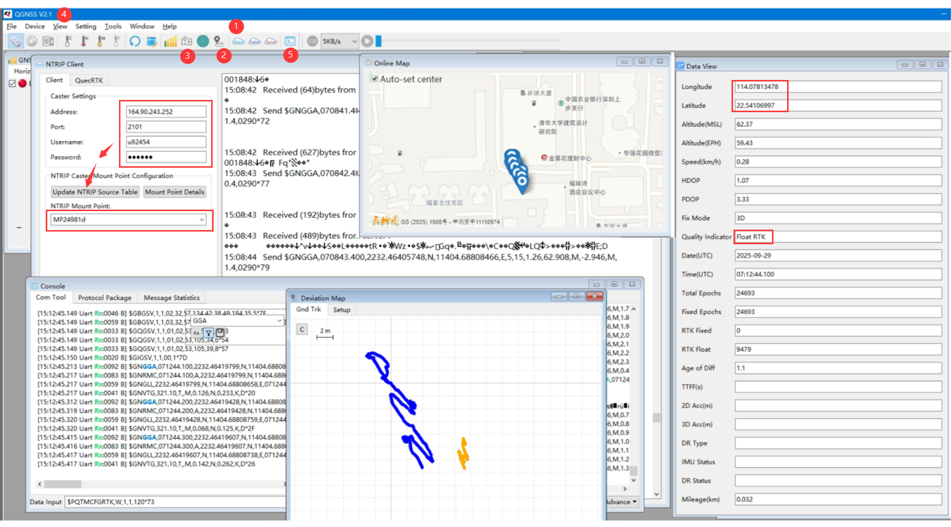
- This data will be transmitted to the mobile station through the caster relay station, so the corresponding parameters of the caster also need to be configured for the mobile station
 ADDRESS:              164.90.243.252
 PORT:                           2101
 MOUNT POINT:                MP24981d
 USERNAME                      u92454
 PASSWORD:                     35XXXX
- Wait for several hours until both the base station and mobile station are stable, then Float RTK appears and RTK positioning is successful
Raspberry Pi
This section is an example of testing instructions using a Raspberry Pi and an LG290P HAT; in fact, Linux operating systems are largely similar, and they can also be adapted to common Linux series motherboards like Jetson and RDK. Tested under an open, clear ☀️ sky, the more open and clearer the weather ☀️, the more accurate the RTK positioning
Environment Setup
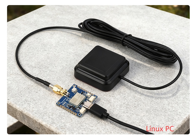
- By connecting via USB to a Linux host, the latest version of the Raspberry Pi system already has the CH343 driver built-in, and it loads the default serial port as ttyACM0
- Download and run a Python3 program in the Raspberry Pi terminal shell interface. Enter the generated IP + port number in the browser to get the Ntrip Client window interface. Enter relevant parameters for Hi-Target, Chihiro, Trimble, or self-built base stations, etc. Here, we test with Hi-Target's CORS account as an example:
wget https://files.waveshare.com/wiki/LG290P-GNSS-RTK-Module/Demo/LG290P-GNSS-RTK-Module-Demo.zip
sudo unzip LG290P-GNSS-RTK-Module-Demo.zip
cd LG290P-GNSS-RTK-Module-Demo/Raspberry_Pi/Python/RTK_Rover/
sudo python3 web_rtk.py
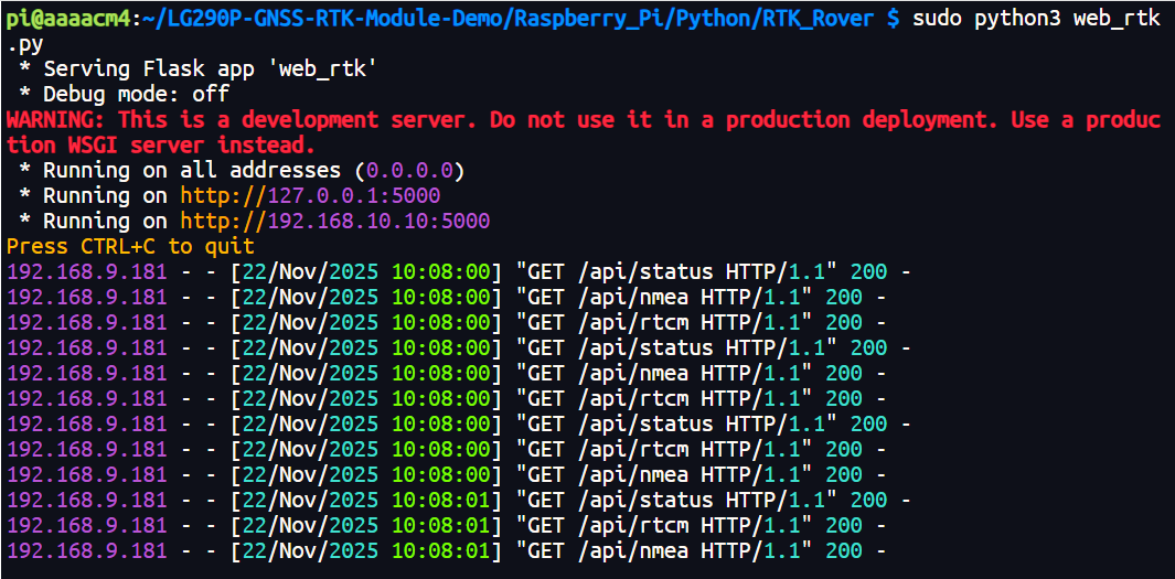
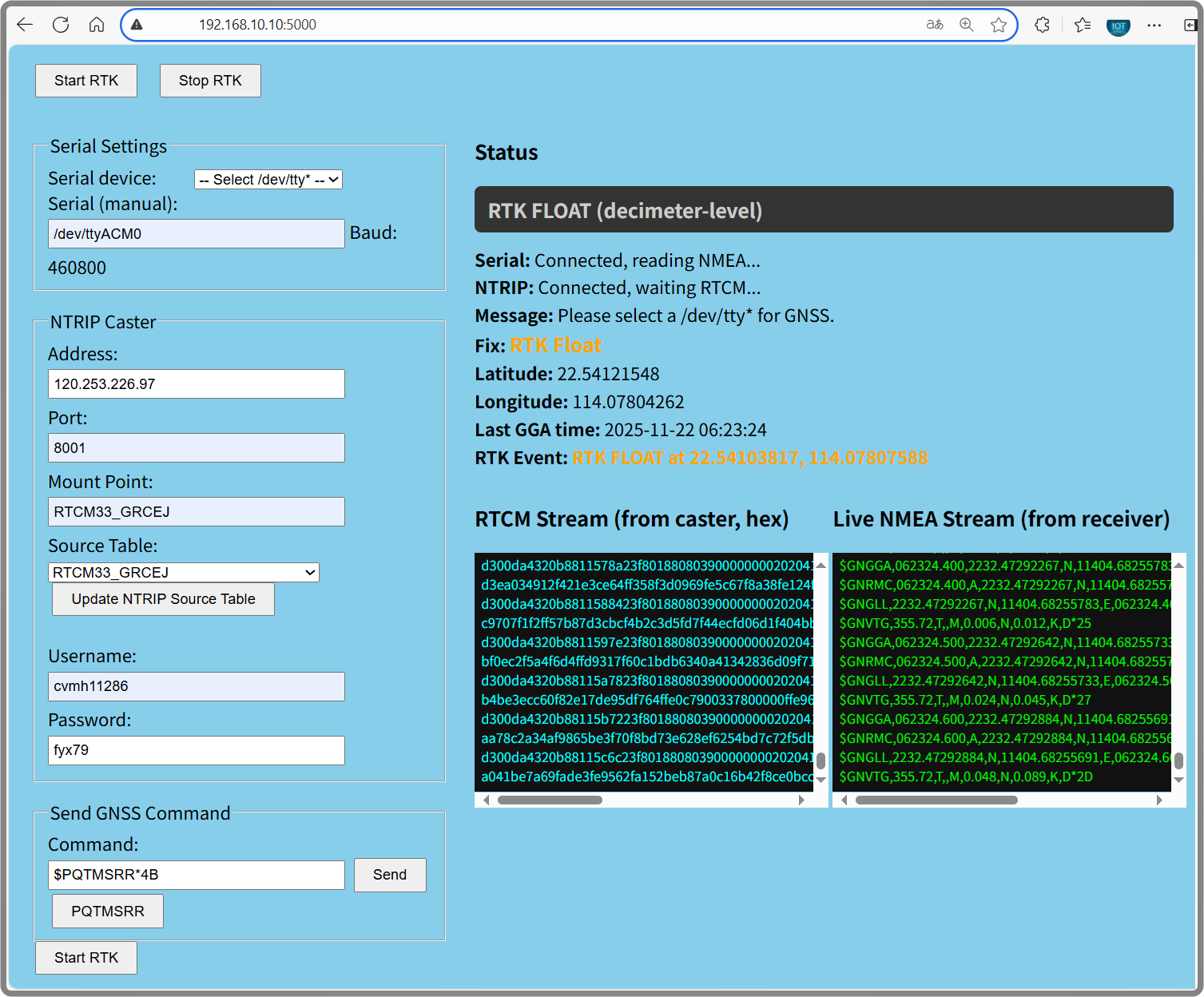
- Please copy the IP address and port number displayed by the program, then paste it into the address bar of a Raspberry Pi or a computer on the same local network:
http://192.168.10.10:5000
- Configure the corresponding serial port number, the default is ttyACM0, copy the Hi-Target RTK parameters to the configuration box, click Start RTK
RTK BASE
Windows systems can use STRSVR to upload base station information to the server. For Linux systems, you can refer to the following steps to install the rtkbase tool to upload the server. Here, the Raspberry Pi is used as an example for testing. The testing steps for Linux hosts such as Jetson are similar, and the demo can be shared:
- Copy the following command lines to the Raspberry Pi terminal
https://github.com/Stefal/rtkbase
git clone https://github.com/Stefal/rtkbase.git
cd rtkbase/tools
sudo ./install.sh --all release
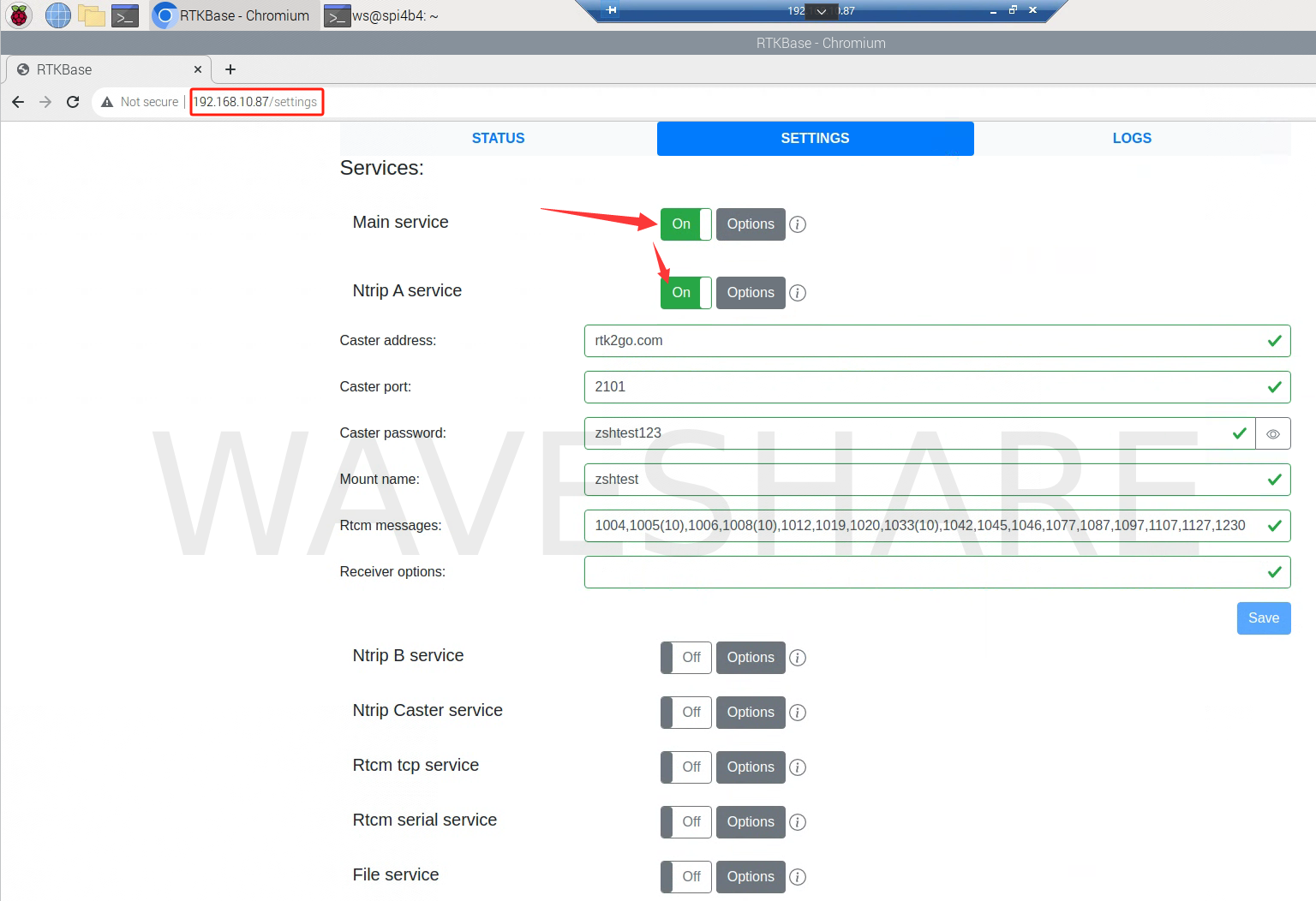
- After correctly installing the tool on the web page, the following prompt will appear:
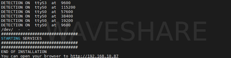
- Then directly open the browser and access the local address (Raspberry Pi IP) (here it is 192.168.10.87), and on the Raspberry Pi side, you need to open the corresponding button to enable the server to be online
ESP32 Test
- LG290P GNSS RTK Module is connected to ESP32 via UART, and the antenna is also connected. Place the module in the open outdoors, or at least place the positioning antenna receiver under the visible sky for testing, the pin connection diagram is as follows:
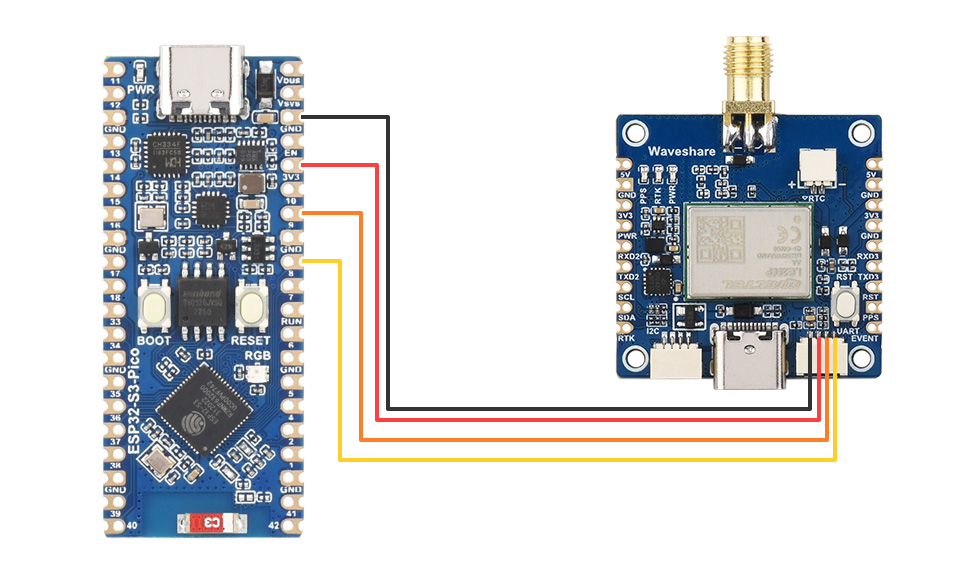
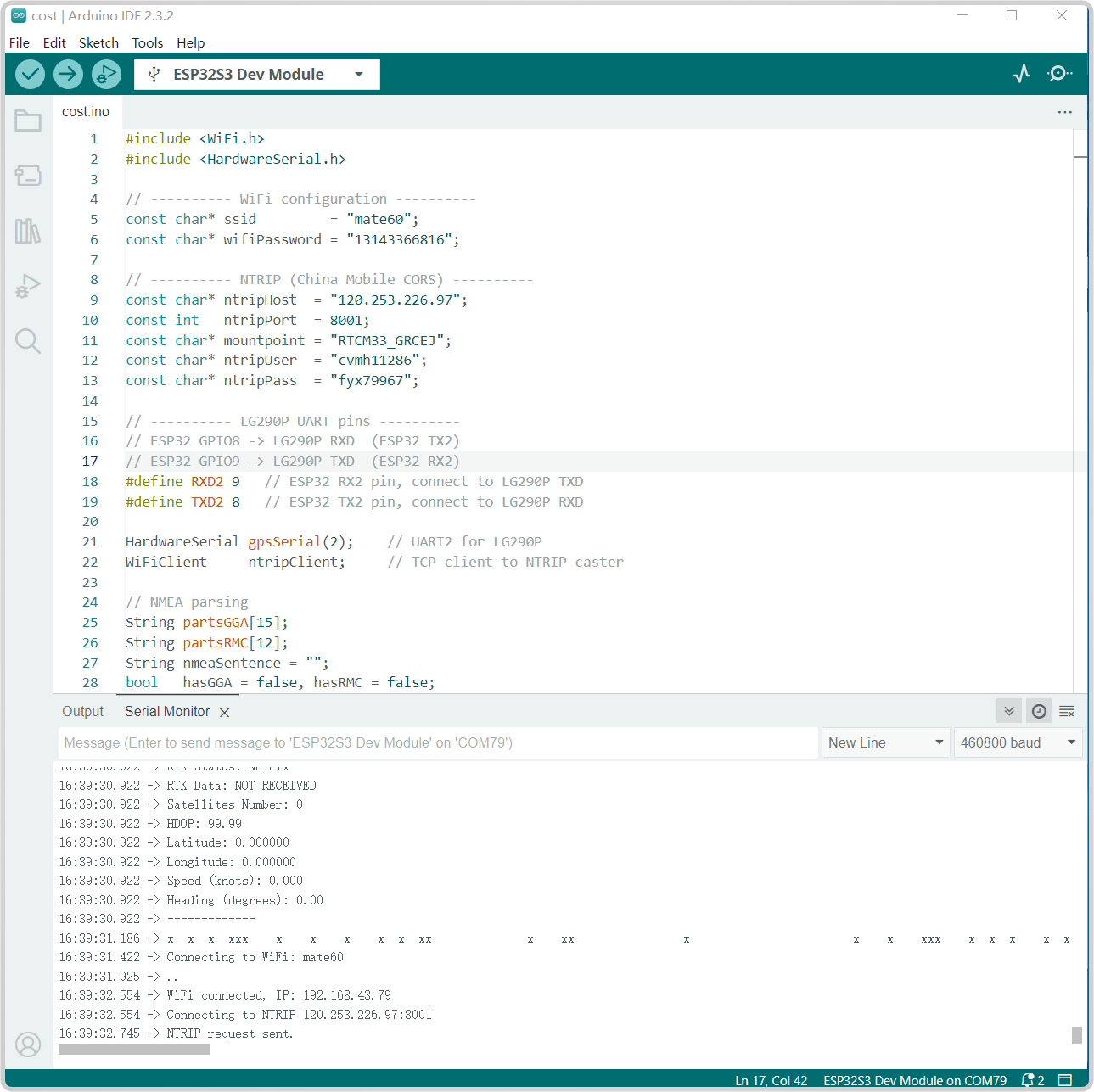
- Take the ESP32-S3 test as an example, set up an ESP32-S3 environment, modify the following parameters in the demo:
//Connect ESP to WiFi to enable access to base station server data
const char* ssid         = "mate60";   //Hotspot SSID
const char* wifiPassword = "131433";  //Corresponding password

// ---------- NTRIP(Here is an example of Hi-Target CORS, modify the following parameters accordingly)----------
const char* ntripHost  = "120.253.226.97";
const int   ntripPort  = 8001;
const char* mountpoint = "RTCM33_GRCEJ";
const char* ntripUser  = "cvmh11286";
const char* ntripPass  = "fyxxx";
- Compile and flash the GetGPS-RTK.ino program to the esp32, and the indoor test results are shown in the figure below:
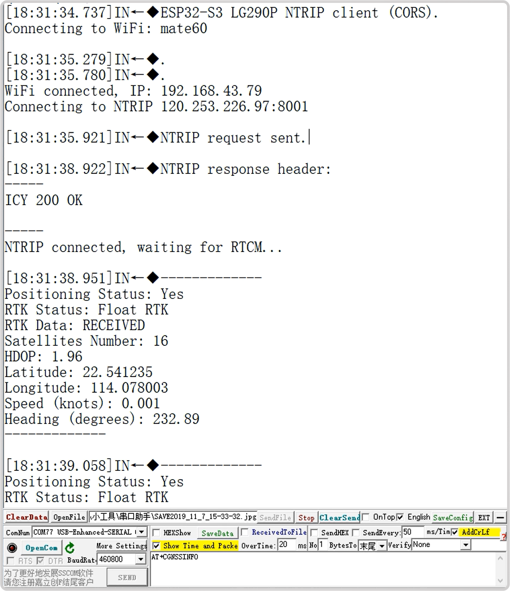
- It is not possible to achieve GNSS and RTK positioning indoors. Bring a laptop to the visible sky and test the results as shown in the following figure. The laptop does not have Arduino environment installed. Here, we use SSCOM to demonstrate:
Raspberry Pi Pico Test
- If you need to use RTK functionality, use the Raspberry Pi Pico 2 W series, and implement RTK positioning similar to ESP32 steps. Here, using the Raspberry Pi Pico 2 as an example, we test standard GNSS positioning. GNSS positioning is also the most basic function of the LG290P GNSS RTK Module. The wiring diagram is as follows:
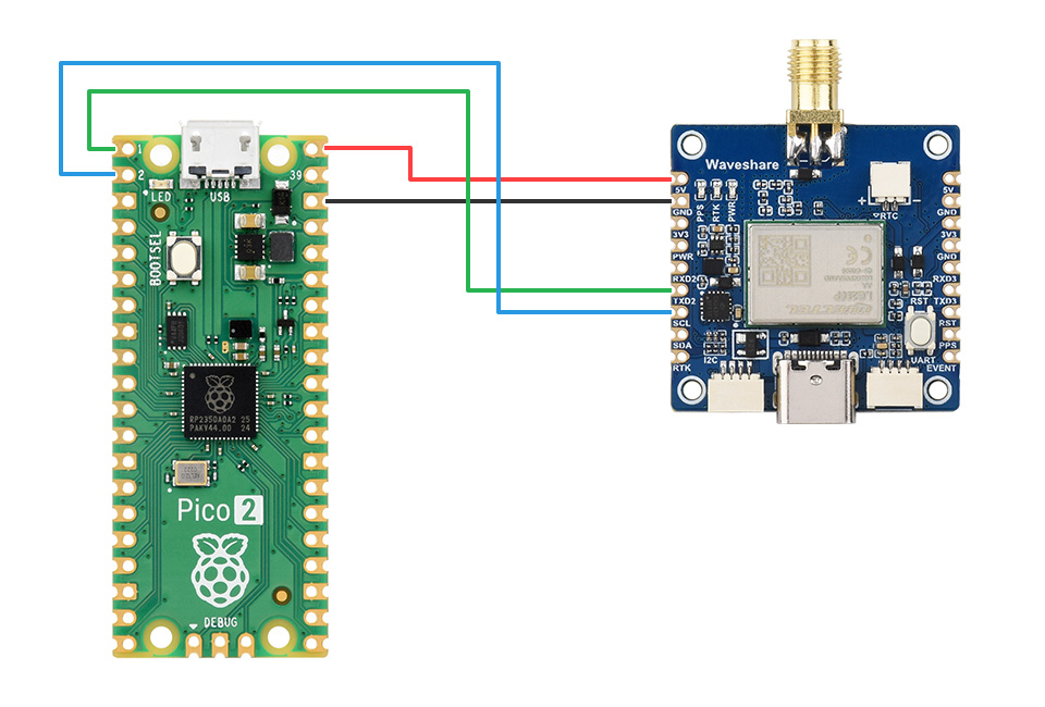
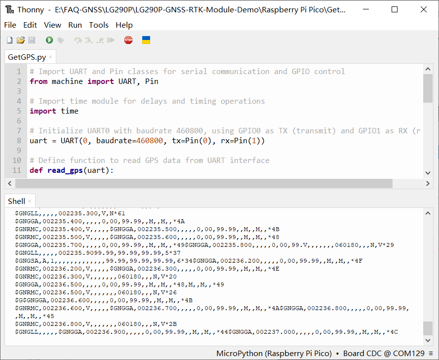
- Opening and running demos in Thonny allows you to obtain the original GNSS messages, as shown in the figure below:
Resources
Documents
Engineering Drawings
Demos
Software
- Windows RTK debugging tools:
Datasheets
FAQ
Question: Why is the positioning bias so large that I can't get the fix RTK?
- Different testing environments may result in different fix RTK times. Please test under clear and open visible skies to obtain better satellite signals;
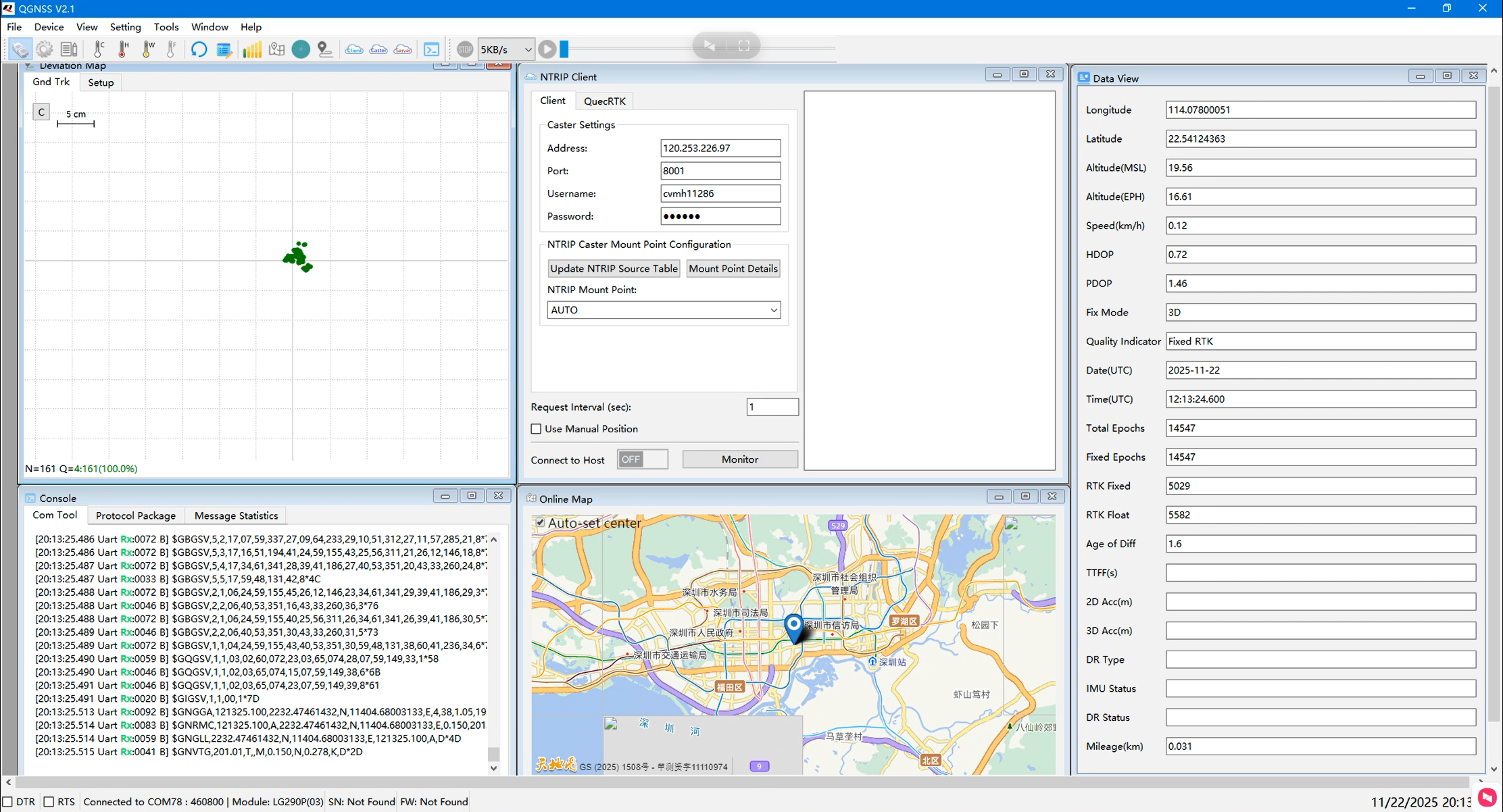
- Taking the connection to the Hi-Target RTK base station as an example, it usually takes 2-30 minutes to obtain float RTK; fix RTK can be obtained within 2-12 hours
- The effect after implementing fix RTK is shown in the figure below:
Question: What should I do if I can't receive the GPS signal and get the location information?
- Due to unstable indoor GNSS satellite searching, the receiver may struggle to pick up satellite signals indoors.
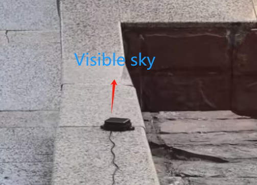
- Connect the GNSS antenna to the IPEX antenna connector and place the receiver with the label facing downwards in an open area with a clear view of the sky (note that testing during rainy weather may not be possible). Node modules may require about 1 minute to receive positioning signals after powering on, while base station modules may require more time.
Question: What is the positioning error when the base station positioning module is used with the node module?
- In actual measurements, it can reach 20cm, and in ideal environments, the error can be even smaller. The error varies in different environments
- If using shared demos and free base station server testing, the error will be larger, because the farther the distance from the base station, the greater the error. It is recommended to purchase an operator base station server for testing to get a more accurate positioning experience
Question: What are the detailed steps for deploying RTKBase on Raspberry Pi?
For more detailed steps, please refer to this Github open-source solution
Question: What points should be checked first if you can't fix?
- 1) Whether the base station is really outputting RTCM (MSM+1005) and whether the corresponding frame can be seen in the QGNSS binary window;
- 2) Whether the Rover role is 1 and the base station is 2, and the parameters have been saved and restarted after power off;
- 3) The frequency band of the NTRIP mount point is the same as that of the receiver, and the account number and mountpoint are correct;
- 4) Whether the antenna field of view and grounding plane meet the standards, first test in an open place;
- 5) The position output frequency matches the serial port baud rate to avoid congestion and packet loss.
Support
Monday-Friday (9:30-6:30) Saturday (9:30-5:30)
Email: services01@spotpear.com
[Tutorial Navigation]
- Overview
- Usage Guide
- Resources
- FAQ
- Question: Why is the positioning bias so large that I can't get the fix RTK?
- Question: What should I do if I can't receive the GPS signal and get the location information?
- Question: What is the positioning error when the base station positioning module is used with the node module?
- Question: What are the detailed steps for deploying RTKBase on Raspberry Pi?
- Question: What points should be checked first if you can't fix?
- Support