


- sales/support
Google Chat:---
- sales
+86-0755-88291180
- sales01
sales@spotpear.com
- sales02
dragon_manager@163.com
- support
tech-support@spotpear.com
- CEO-Complaints
zhoujie@spotpear.com
- Only Tech-Support
WhatsApp:13246739196
- Purchase/Shipping/Refund
WhatsApp:13424403025
- HOME
- >
- ARTICLES
- >
- Common Moudle
- >
- ESP
ESP32-S3-ePaper-3.97 User Guide
ESP32-S3-ePaper-3.97
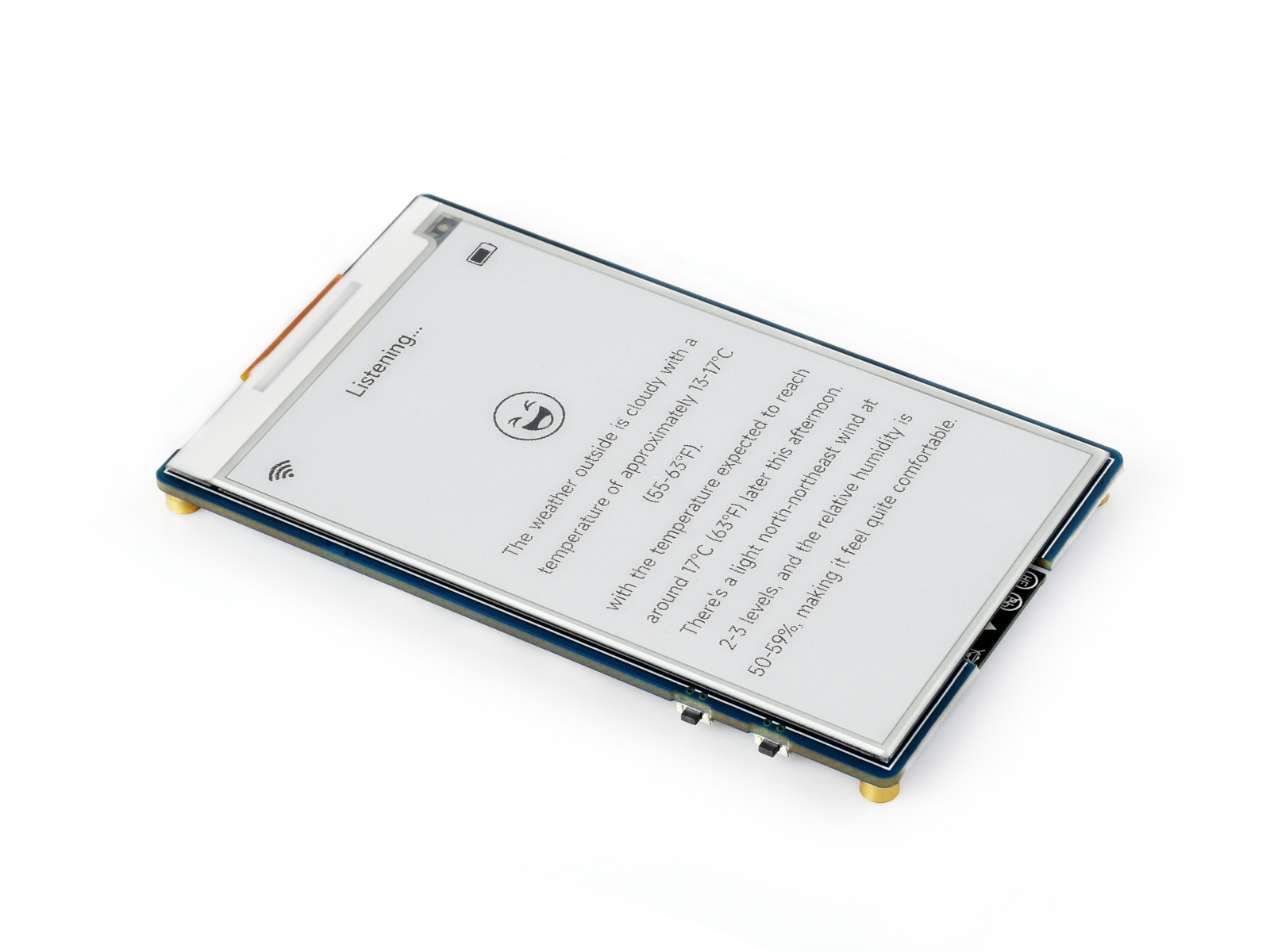
This product is a high-performance, highly integrated microcontroller development board designed by Waveshare. It features the ESP32-S3 microcontroller, supporting dual-mode Wi-Fi and BLE communication. The board comes with a 3.97inch e-Paper display, which offers extremely low power consumption, is viewable under ambient light, and is suitable for portable devices and long-endurance scenarios. It integrates an RTC real-time clock, an SHTC3 temperature and humidity sensor, a TF card slot, a low-power audio codec chip, and a power management chip. It provides a flexible and reliable development platform for applications such as IoT endpoints, electronic shelf labels, and portable displays.
Features
- Equipped with ESP32-S3R8 high-performance Xtensa 32-bit LX7 dual-core processor, with a clock frequency up to 240MHz
- Supports 2.4GHz Wi-Fi (802.11 b/g/n) and Bluetooth 5 (LE) with an onboard antenna.
- Built-in 512KB SRAM and 384KB ROM, with stacked 8MB PSRAM and external 16MB Flash
- Features a 3.97inch e-paper display with a resolution of 800 × 480, offering high contrast, wide viewing angles, and other characteristics
- Onboard audio codec chip supports voice capture and playback, facilitating AI voice interaction applications
- Onboard QMI8658 6-axis IMU (3-axis accelerometer and 3-axis gyroscope) enables motion posture detection, step counting, and other functions
- Onboard PCF85063 RTC real-time clock and SHTC3 temperature and humidity sensor enable precise RTC time management and environmental monitoring
- Onboard TG28 power management chip accepts a 3.7V MX1.25 lithium battery for uninterrupted power supply. A backup battery interface is reserved to ensure RTC functionality continues when the main battery is replaced
- The TG28 provides an efficient power management solution, supports outputting multiple configurable voltages, and integrates charging and battery management functions, helping to extend battery life
- Utilizes a Type-C interface, improving user convenience and device compatibility
- Onboard TF card slot enables storage expansion and fast data transfer, suitable for data logging, media playback, and other scenarios, simplifying circuit design
- Onboard rotary button, along with side BOOT and PWR buttons, supports customizable key functions for more flexible development and use
Onboard Resources
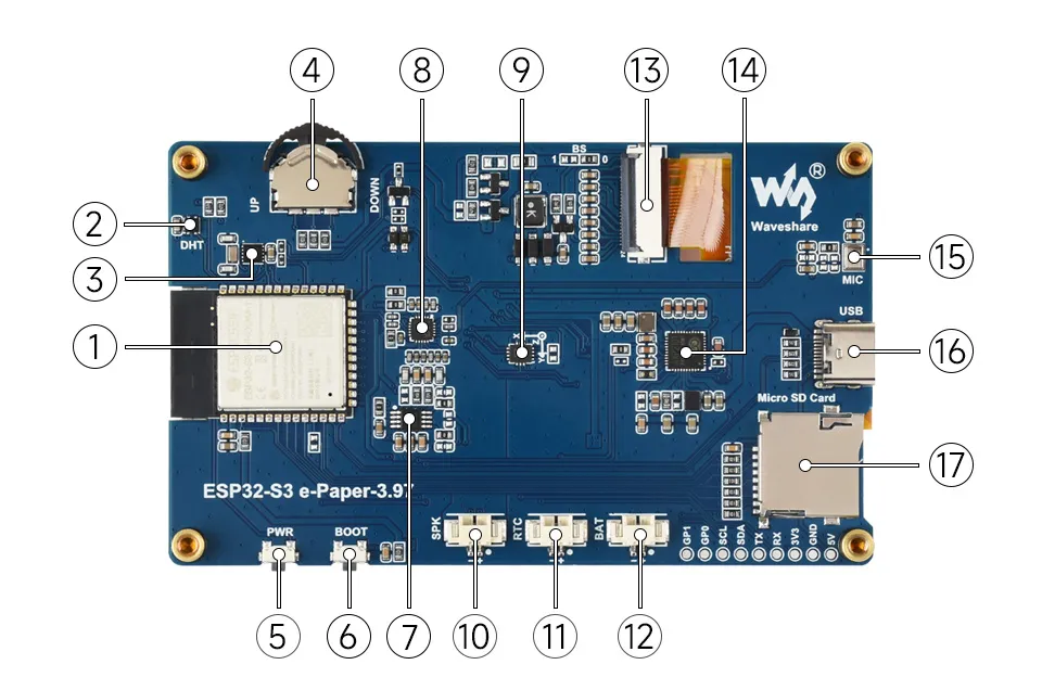
- ESP32-S3-WROOM-1-N16R8 Wi-Fi and Bluetooth SoC, up to 240MHz operating frequency, stacked with 16MB Flash and 8MB PSRAM
- SHTC3 Temperature and Humidity Sensor Provides ambient temperature and humidity measurement, enabling environmental monitoring function
- PCF85063 RTC clock chip, supporting time-keeping functionality
- Rotary Button Supports customizable button functions in three directions
- PWR Key Can be used with programs to control all power functions when powered by a lithium battery
- BOOT Button Press and hold the BOOT button to power on again to enter download mode
- NS4150B Audio power amplifier chip
- ES8311 Low-power audio codec chip
- QMI8658 6-axis IMU includes a 3-axis gyroscope and a 3-axis accelerometer
- MX1.25 Speaker Header
- MX1.25 RTC Backup Battery Header Used to power the RTC when no battery is connected to the lithium battery interface
- MX1.25 Lithium Battery Header MX1.25 2PIN connector for connecting a 3.7V lithium battery, supports charging and discharging
- 3.97inch e-Paper Display Interface
- TG28 Highly integrated power management chip
- Microphone
- Type-C Interface Used for program flashing and log printing
- **TF Card Slot ** Supports FAT32-formatted TF card for data expansion
Interfaces
Dimensions

Development Methods
The ESP32-S3-ePaper-3.97 supports two development frameworks: Arduino IDE and ESP-IDF, offering flexibility for developers. You can choose the appropriate development tool based on project requirements and personal preference.
Each method has its advantages, and developers can select based on their needs and skill level. Arduino is simple to learn and easy to get started with, suitable for beginners and non-professionals; ESP-IDF provides more advanced development tools and stronger control capabilities, suitable for developers with professional backgrounds or those with higher performance requirements, and is more suitable for complex project development.
Arduino IDE is a convenient, flexible, and easy-to-use open-source electronics prototyping platform. It requires minimal foundational knowledge, allowing for rapid development after a short learning period. Arduino has a vast global community that provides a wealth of open-source code, project examples, tutorials, and rich libraries that encapsulate complex functionalities, enabling developers to implement various features quickly. You can refer to the Working with Arduino to complete the initial setup, and the tutorial also provides related demos for reference.
ESP-IDF (Espressif IoT Development Framework) is a professional development framework released by Espressif for its ESP series chips. It is developed based on the C language, including a compiler, debugger, and flashing tool, etc. It supports development via command line or an Integrated Development Environment (such as Visual Studio Code with the Espressif IDF plugin), which provides features like code navigation, project management, and debugging, etc. We recommend using VS Code for development. For the specific configuration process, please refer to the Working with ESP-IDF. The tutorial also provides relevant demos for reference.
Working with Arduino
Setting Up Development Environment
1. Installing and Configuring Arduino IDE
Please refer to the tutorial Installing and Configuring Arduino IDE Tutorial to download and install the Arduino IDE and add ESP32 support.
2. Installing Libraries
- When installing Arduino libraries, there are typically two methods: Online Installation and Offline Installation. If the library installation requires offline installation, you must use the provided library file.
- For most libraries, users can easily search and install them through the online Library Manager in the Arduino software. However, some open-source libraries or custom libraries are not synchronized to the Arduino Library Manager, so they cannot be acquired through online searches. In this case, users can only manually install these libraries offline.
- The sample program package for the ESP32-S3-ePaper-3.97 development board can be downloaded from here. The
Arduino\librariesdirectory within the package already includes all the library files required for this tutorial.
| Library/File Name | Description | Version | Installation Method |
|---|---|---|---|
| SensorLib | Sensor library | v0.3.1 | "Install Online" or "Install Offline" |
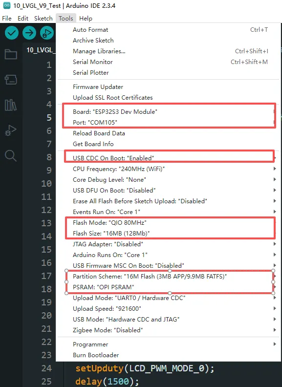
3. Arduino Project Parameter Settings
Demo
The Arduino demos are located in the Arduino/examples directory of the demo package.
| Demo | Basic Program Description | Dependency Library |
|---|---|---|
| 01_Audio_Test | Drives ES8311 to play audio | - |
| 02_E-Paper_Example | 3.97inch e-Paper display demo | - |
| 03_I2C_PCF85063 | RTC demo | - |
| 04_I2C_SHTC3 | Temperature and humidity sensor demo | SensorLib |
| 05_SD_Test | TF card demo | - |
| 06_QMI8658A | 6-axis gyroscope demo | SensorLib |
01_Audio_Test
Demo Description
- This example drives the ES8311 audio codec to play music.
Hardware Connection
- Connect the board to the computer using a USB cable
Code Analysis
Configure and initialize the ES8311 audio codec.
  void setup() {
    Serial.begin(115200);
    Wire.begin(I2C_SDA, I2C_SCL);
    pinMode(PA_CTRL, OUTPUT);
    digitalWrite(PA_CTRL, HIGH);
    es8311_codec_init();

    setupI2S();
    Serial.println("I2S Initialized");
  }
Continuously write built-in audio data to the I2S bus for looped playback.
i2s.write((uint8_t *)audio_data, AUDIO_SAMPLES * 2);
Operation Result
- The device will play auido directly without showing content on the screen
02_E-Paper_Example
Demo Description
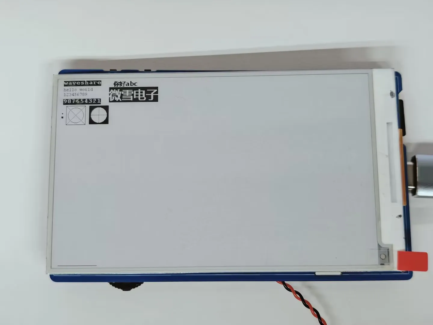
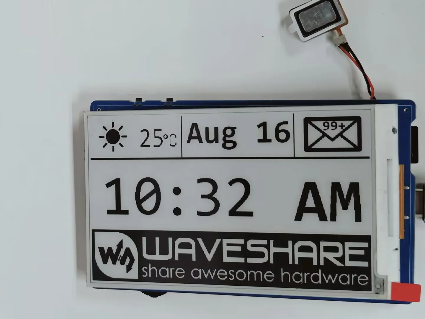
- This is a local Arduino example for the 3.97inch e-Paper display. It initializes and clears the e-Paper display, displays an image, draws basic shapes and text, and performs partial refresh to dynamically display the time.
Hardware Connection
- Connect the board to the computer using a USB cable
Code Analysis
Display a predefined image.
  #if 1   // show bmp
    EPD_3IN97_Init_Fast();
    printf("show image for array\r\n");
    EPD_3IN97_Display(gImage_image);
    DEV_Delay_ms(1500);
  #endif
Draw basic shapes, Chinese/English text, numbers, and refresh the display.
 #if 1   // Drawing on the image
    //1.Select Image
    EPD_3IN97_Init();
    printf("SelectImage:BlackImage\r\n");
    Paint_SelectImage(BlackImage);
    Paint_Clear(WHITE);

    // 2.Drawing on the image
    Debug("Drawing:BlackImage\r\n");
    Paint_DrawPoint(10, 80, BLACK, DOT_PIXEL_1X1, DOT_STYLE_DFT);
    Paint_DrawPoint(10, 90, BLACK, DOT_PIXEL_2X2, DOT_STYLE_DFT);
    Paint_DrawPoint(10, 100, BLACK, DOT_PIXEL_3X3, DOT_STYLE_DFT);
    Paint_DrawLine(20, 70, 70, 120, BLACK, DOT_PIXEL_1X1, LINE_STYLE_SOLID);
    Paint_DrawLine(70, 70, 20, 120, BLACK, DOT_PIXEL_1X1, LINE_STYLE_SOLID);
    Paint_DrawRectangle(20, 70, 70, 120, BLACK, DOT_PIXEL_1X1, DRAW_FILL_EMPTY);
    Paint_DrawRectangle(80, 70, 130, 120, BLACK, DOT_PIXEL_1X1, DRAW_FILL_FULL);
    Paint_DrawCircle(45, 95, 20, BLACK, DOT_PIXEL_1X1, DRAW_FILL_EMPTY);
    Paint_DrawCircle(105, 95, 20, WHITE, DOT_PIXEL_1X1, DRAW_FILL_FULL);
    Paint_DrawLine(85, 95, 125, 95, BLACK, DOT_PIXEL_1X1, LINE_STYLE_DOTTED);
    Paint_DrawLine(105, 75, 105, 115, BLACK, DOT_PIXEL_1X1, LINE_STYLE_DOTTED);
    Paint_DrawString_EN(10, 0, "waveshare", &Font16, BLACK, WHITE);
    Paint_DrawString_EN(10, 20, "hello world", &Font12, WHITE, BLACK);
    Paint_DrawNum(10, 33, 123456789, &Font12, BLACK, WHITE);
    Paint_DrawNum(10, 50, 987654321, &Font16, WHITE, BLACK);
    Paint_DrawString_CN(130, 0, " 你好 abc", &Font12CN, BLACK, WHITE);
    Paint_DrawString_CN(130, 20, "微雪电子", &Font24CN, WHITE, BLACK);

    printf("EPD_Display\r\n");
    EPD_3IN97_Display_Base(BlackImage);
    DEV_Delay_ms(3000);
 #endif
Operation Result
The screen refreshes and displays the content.
03_I2C_PCF85063
Demo Description
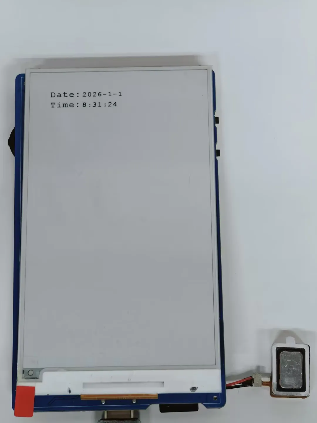
- This example uses the onboard PCF85063 RTC chip to dynamically display time on the 3.97inch e-Paper screen, combining it with the I2C interface RTC real-time clock module.
Hardware Connection
- Connect the board to the computer using a USB cable
Code Analysis
Continuously reads the RTC time, formats it into a string, and performs a partial refresh on the e-paper to display it.
  void i2c_rtc_loop_task(void *arg)
  {
    char buff[80];
    for(;;)
    {
      RtcDateTime_t datetime = rtc_dev->get_rtcTime();
      printf("%d/%d/%d %d:%d:%d \n",datetime.year,datetime.month,datetime.day,datetime.hour,datetime.minute,datetime.second);

      Paint_NewImage(BlackImage, Font20.Height *3, Font20.Width * 8, 270, WHITE);
      Paint_SelectImage(BlackImage);
      Paint_Clear(WHITE);

      sprintf(buff, "%d-%d-%d", datetime.year,datetime.month,datetime.day);
      Paint_DrawString_EN(0, 5, buff, &Font20, WHITE, BLACK);
      sprintf(buff, "%d:%d:%d", datetime.hour,datetime.minute,datetime.second);
      Paint_DrawString_EN(0, 35, buff, &Font20, WHITE, BLACK);

      EPD_3IN97_Display_Partial(BlackImage, 50, 250, 50 + Font20.Height*3 , 250 + Font20.Width * 8);

      vTaskDelay(pdMS_TO_TICKS(500));
    }
  }
Operation Result
The e-Paper display partially refreshes to show the time.
04_I2C_SHTC3
Demo Description
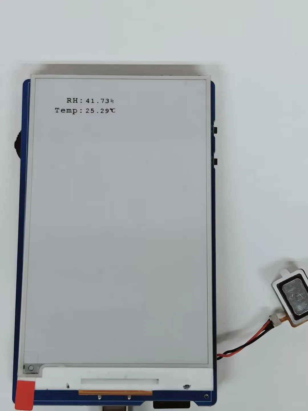
- This example uses the onboard SHTC3 temperature and humidity sensor to dynamically display temperature and humidity data on the 3.97inch e-Paper display.
Hardware Connection
- Connect the board to the computer using a USB cable
Code Analysis
Continuously reads sensor data and partially refreshes the e-Paper to display temperature and humidity.
void i2c_SHTC3_loop_task(void *arg)
{
  char buff[80];
  for(;;)
  {
    shtc3_data_t shtc3_data = shtc3_dev->readTempHumi();
    printf("RH:%.2f%%,Temp:%.2f°C \n",shtc3_data.RH,shtc3_data.Temp);

    Paint_NewImage(BlackImage, Font20.Height *3, Font20.Width * 8, 270, WHITE);
    Paint_SelectImage(BlackImage);
    Paint_Clear(WHITE);

    sprintf(buff, "%.2f%%",shtc3_data.RH);
    Paint_DrawString_EN(0, 5, buff, &Font20, WHITE, BLACK);
    sprintf(buff, "%.2f", shtc3_data.Temp);
    Paint_DrawString_EN(0, 35, buff, &Font20, WHITE, BLACK);
    Paint_DrawString_CN(Font20.Width * 5, 30, "℃", &Font12CN, WHITE, BLACK);

    EPD_3IN97_Display_Partial(BlackImage, 50, 250, 50 + Font20.Height*3 , 250 + Font20.Width * 8);

    vTaskDelay(pdMS_TO_TICKS(1000));
  }
}
Operation Result
The e-Paper display partially refreshes to show the temperature and humidity.
05_SD_Test
Demo Description
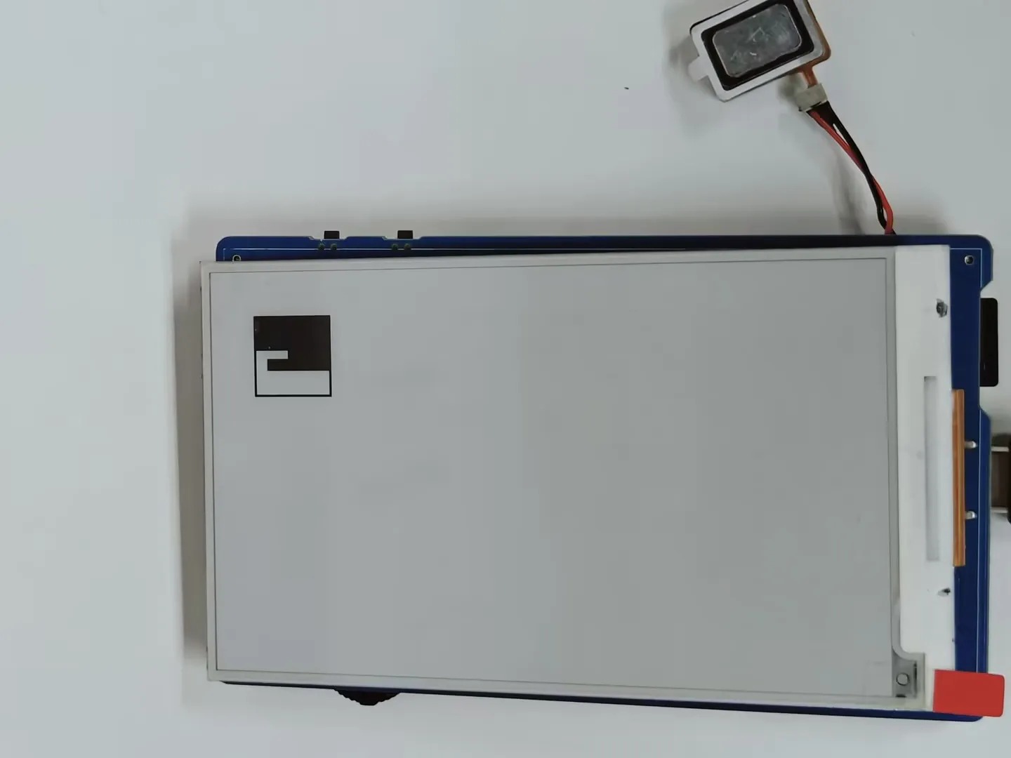
- This example reads BMP images from a TF card and refreshes them on the e-Paper display.
Hardware Connection
- Connect the board to the computer using a USB cable
- Insert the TF card module with a TF card containing a bmp folder with images in the root directory.
Code Analysis
Configure and mount the TF card.
  //sdcard init
  Serial.begin(115200);
  delay(1000);
  SD_MMC.setPins(SD_CLK, SD_CMD, SD_D0, SD_D1, SD_D2, SD_D3);
  if (!SD_MMC.begin( "/sdcard", true)) {
      printf("TF card failed to mount\r\n");
      return;
  }
  printf("TF card success to mount\r\n");
Display images.
  printf("show BMP-------------------------\r\n");
  EPD_3IN97_Init_Fast();

  Paint_Clear(WHITE);
  GUI_ReadBmp("/sdcard/bmp/100x100.bmp", 50, 50);
  EPD_3IN97_Display_Fast(Image);
  printf("100*100 BMP Load OK!\r\n");
  DEV_Delay_ms(1000);

  Paint_Clear(WHITE);
  GUI_ReadBmp("/sdcard/bmp/3in97.bmp", 50, 0);
  EPD_3IN97_Display_Fast(Image);
  printf("800*480 BMP Load OK!\r\n");
  DEV_Delay_ms(3000);
Display 4-grayscale BMP image.
  EPD_3IN97_Init_4GRAY();
  Paint_NewImage(Image, EPD_3IN97_WIDTH, EPD_3IN97_HEIGHT, 0, WHITE);
  Paint_SetScale(4);
  Paint_Clear(WHITE);
  if(GUI_ReadBmp_4Gray("/sdcard/bmp/3in97_4Gray.bmp", 0, 0) == 0){
      printf("4Gray BMP Load OK!\r\n");
  }else{
      printf("4Gray BMP Load Failed!\r\n");
  }
  EPD_3IN97_Display_4Gray(Image);
  DEV_Delay_ms(3000);
Operation Result
Reads and displays images from the TF card.

06_QMI8658A
Demo Description
- This example uses the onboard QMI8658 6-axis IMU sensor and displays the values on the e-Paper screen.
Hardware Connection
- Connect the board to the computer using a USB cable
Code Analysis
Check if the data is ready, read and print the sensor data, and call the display function to update the display data on the e-Paper screen.
   if (qmi.getDataReady()) {
      if (qmi.getAccelerometer(acc.x, acc.y, acc.z)) {
          Serial.print("ACCEL.x:"); Serial.print(acc.x); Serial.print(",");
          Serial.print("ACCEL.y:"); Serial.print(acc.y); Serial.print(",");
          Serial.print("ACCEL.z:"); Serial.print(acc.z); Serial.println();
      }
      if (qmi.getGyroscope(gyr.x, gyr.y, gyr.z)) {
          Serial.print(" GYRO.x:"); Serial.print(gyr.x); Serial.print(",");
          Serial.print(" GYRO.y:"); Serial.print(gyr.y); Serial.print(",");
          Serial.print(" GYRO.z:"); Serial.print(gyr.z); Serial.println();
      }
      qmi8658_data_show();
  }
Operation Result
The e-Paper display partially refreshes to show 6-axis gyroscope sensor data.
ESP-IDF
Setting up the Development Environment
For the ESP32-S3-ePaper-3.97 development board, you need to use ESP-IDF V5.5.0 or higher.
The following guide uses Windows as an example, demonstrating development using VS Code + the ESP-IDF extension. macOS and Linux users should refer to the official documentation.
Install the ESP-IDF Development Environment
Download the installation manager from the ESP-IDF Installation Manager page. This is Espressif's latest cross-platform installer. The following steps demonstrate how to use its offline installation feature.
Click the Offline Installer tab on the page, then select Windows as the operating system and choose your desired version from the filter bar.

After confirming your selection, click the download button. The browser will automatically download two files: the ESP-IDF Offline Package (.zst) and the ESP-IDF Installer (.exe).

Please wait for both files to finish downloading.
Once the download is complete, double-click to run the ESP-IDF Installer (eim-gui-windows-x64.exe).
The installer will automatically detect if the offline package exists in the same directory. Click Install from archive.

Next, select the installation path. We recommend using the default path. If you need to customize it, ensure the path does not contain Chinese characters or spaces. Click Start installation to proceed.

When you see the following screen, the ESP-IDF installation is successful.

We recommend installing the drivers as well. Click Finish installation, then select Install driver.

Install Visual Studio Code and the ESP-IDF Extension
Download and install Visual Studio Code.
During installation, it is recommended to check Add "Open with Code" action to Windows Explorer file context menu to facilitate opening project folders quickly.
In VS Code, click the Extensions icon
 in the Activity Bar on the side (or use the shortcut Ctrl + Shift + X) to open the Extensions view.
Enter ESP-IDF in the search box, locate the ESP-IDF extension, and click Install.

For ESP-IDF extension versions ≥ 2.0, the extension will automatically detect and recognize the ESP-IDF environment installed in the previous steps, requiring no manual configuration.
Demo
The ESP-IDF demos are located in the ESP-IDF directory of the demo package.
| Demo | Basic Description |
|---|---|
| 01_E-Paper_Example | 3.97inch e-Paper display demo |
| 02_Mic_test | Playback of sound recorded by the microphone through the speaker |
| 03_Music | Mount TF card and read/play music files from it |
| 04_SD_Test | Mount TF card, read images from it, and refresh the display |
| 05_QMI8658A | 6-axis gyroscope demo |
| 06_I2C_PCF85063 | RTC demo |
| 07_I2C_SHTC3 | Temperature and humidity sensor demo |
| 08_ESP32-S3_e-Paper-3.97 | Integrate file browser, clock, calendar, alarm, weather, network configuration, audio playback, and e-reader functions |
01_E-Paper_Example
Demo Description
- This example demonstrates a native ESP-IDF program for the 3.97inch e-Paper display. It initializes and clears the e-Paper screen, displays an image, draws basic shapes and text, and performs partial refresh to dynamically display the time.
Hardware Connection
- Connect the development board to the computer
Code Analysis
Display a predefined image:
  #if 1
    ESP_LOGI(TAG,"2.show BMP");
    EPD_Init_Fast();
    EPD_Display(gImage_image);
    vTaskDelay(pdMS_TO_TICKS(2000));
 #endif
Draw basic shapes, Chinese/English text, numbers, and refresh the display:
  #if 1
    ESP_LOGI(TAG,"3.Paint_NewImage");
    EPD_Init();
    Paint_NewImage(Image_Mono, EPD_WIDTH, EPD_HEIGHT, 0, WHITE);
    Paint_SelectImage(Image_Mono);
    Paint_Clear(WHITE);
    // Drawing on the image
    Paint_DrawPoint(5, 10, BLACK, DOT_PIXEL_1X1, DOT_STYLE_DFT);
    Paint_DrawPoint(5, 25, BLACK, DOT_PIXEL_2X2, DOT_STYLE_DFT);
    Paint_DrawPoint(5, 40, BLACK, DOT_PIXEL_3X3, DOT_STYLE_DFT);
    Paint_DrawPoint(5, 55, BLACK, DOT_PIXEL_4X4, DOT_STYLE_DFT);

    Paint_DrawLine(20, 10, 70, 60, BLACK, DOT_PIXEL_1X1, LINE_STYLE_SOLID);
    Paint_DrawLine(70, 10, 20, 60, BLACK, DOT_PIXEL_1X1, LINE_STYLE_SOLID);
    Paint_DrawLine(170, 15, 170, 55, BLACK, DOT_PIXEL_1X1, LINE_STYLE_DOTTED);
    Paint_DrawLine(150, 35, 190, 35, BLACK, DOT_PIXEL_1X1, LINE_STYLE_DOTTED);

    Paint_DrawRectangle(20, 10, 70, 60, BLACK, DOT_PIXEL_1X1, DRAW_FILL_EMPTY);
    Paint_DrawRectangle(85, 10, 130, 60, BLACK, DOT_PIXEL_1X1, DRAW_FILL_FULL);

    Paint_DrawCircle(170, 35, 20, BLACK, DOT_PIXEL_1X1, DRAW_FILL_EMPTY);
    Paint_DrawCircle(170, 85, 20, BLACK, DOT_PIXEL_1X1, DRAW_FILL_FULL);

    Paint_DrawNum(5, 180, 123456789, &Font24, BLACK, WHITE);
    Paint_DrawString_CN(5, 100,"你好 abc", &Font16_UTF8, BLACK, WHITE);
    Paint_DrawString_CN(5, 130, "微雪电子", &Font24_UTF8, WHITE, BLACK);

    EPD_Display_Base(Image_Mono);
    vTaskDelay(pdMS_TO_TICKS(2000));
    #endif
Operation Result
- The e-Paper display refreshes and shows content.
02_Mic_test
Demo Description
- Demonstrates how to get data from the microphone and then play it through the speaker
Hardware Connection
- Connect the development board to the computer
Code Analysis
i2c_master_Init();: Initializes the I2C bus.user_ui_init();: Initializes the global UI.user_button_init();: Initializes the audio interface.
Operation Result
The screen shows nothing.
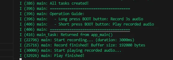
Long press the BOOT button to enter recording mode. Speak into the MIC, and it will automatically stop after 3 seconds.
Click the BOOT button to play the recorded sound. (If no recording exists, the played sound will be very harsh.)
Serial port prints:
03_Music
Demo Description
- Mounts a TF card and reads/plays audio files from it.
Hardware Connection
- Connect the development board to the computer
- Connect a speaker to the SPK interface.
Code Analysis
_sdcard_init();: Initializes the TF card and reads the audio files from it.i2c_master_init();: Initializes the I2C bus, providing a communication link for configuration command transmission to the ES8311 audio codec.audio_player_play(audio_fp);: Starts the audio player, reads the opened MP3 file, and drives the speaker through the ES8311 for playback.
Operation Result
- The screen shows nothing.
- The speaker plays audio.
04_SD_Test
Demo Description
- This example reads BMP images from a TF card and refreshes them on the e-Paper display.
Hardware Connection
- Connect the development board to the computer
- Place the bmp folder from the current program into the root directory of a TF card, then insert the TF card module.
Code Analysis
_sdcard_init();: Initializes the TF card and reads the audio files from it.epaper_port_init();: Initializes the low-level hardware ports for the e-Paper (pins, communication bus, etc.).EPD_Init();/EPD_Clear();: Initializes the e-Paper driver parameters and clears the screen to a white background.GUI_ReadBmp("/sdcard/bmp/100x100.bmp", 50, 50);/EPD_Display_Fast(BlackImage);: Reads a BMP image from the TF card and performs a fast refresh to display it.GUI_ReadBmp_4Gray("/sdcard/bmp/3in97_4Gray.bmp", 0, 0);/EPD_Display_4Gray(BlackImage);: Reads and displays a 4-grayscale BMP image from the TF card.
Operation Result
Reads and displays images from the TF card.
05_QMI8658A
Demo Description
- This example reads BMP images from a TF card and refreshes them on the e-Paper display.
Hardware Connection
- Connect the development board to the computer
- Place the bmp folder from the current program into the root directory of a TF card, then insert the TF card module.
Code Analysis
epaper_port_init();/EPD_Init();/EPD_Clear();calling EPD_Display_Partial for a partial e-Paper refresh after drawing values: Initializes the e-Paper's low-level hardware ports and driver parameters, clears the screen to a white background.i2c_master_init();: Initializes the I2C bus, providing a communication link for configuring and reading data from the QMI8658 sensor.xTaskCreate(qmi8658_test_task, "qmi8658_test_task", 4096, i2c_bus_handle, 5, NULL);: Creates a FreeRTOS task to execute the QMI8658 sensor data reading logic.qmi8658_is_data_ready(&dev, &ready);: Checks if the sensor data is ready, and only reads data when it is ready.qmi8658_read_sensor_data(&dev, &data);: Reads the sensor's acceleration, gyroscope, temperature, and timestamp data, and prints them via the serial port.draw_qmi8658_data_to_epaper(&data);: After drawing the values, callsEPD_Display_Partialfor a partial refresh to display the data.
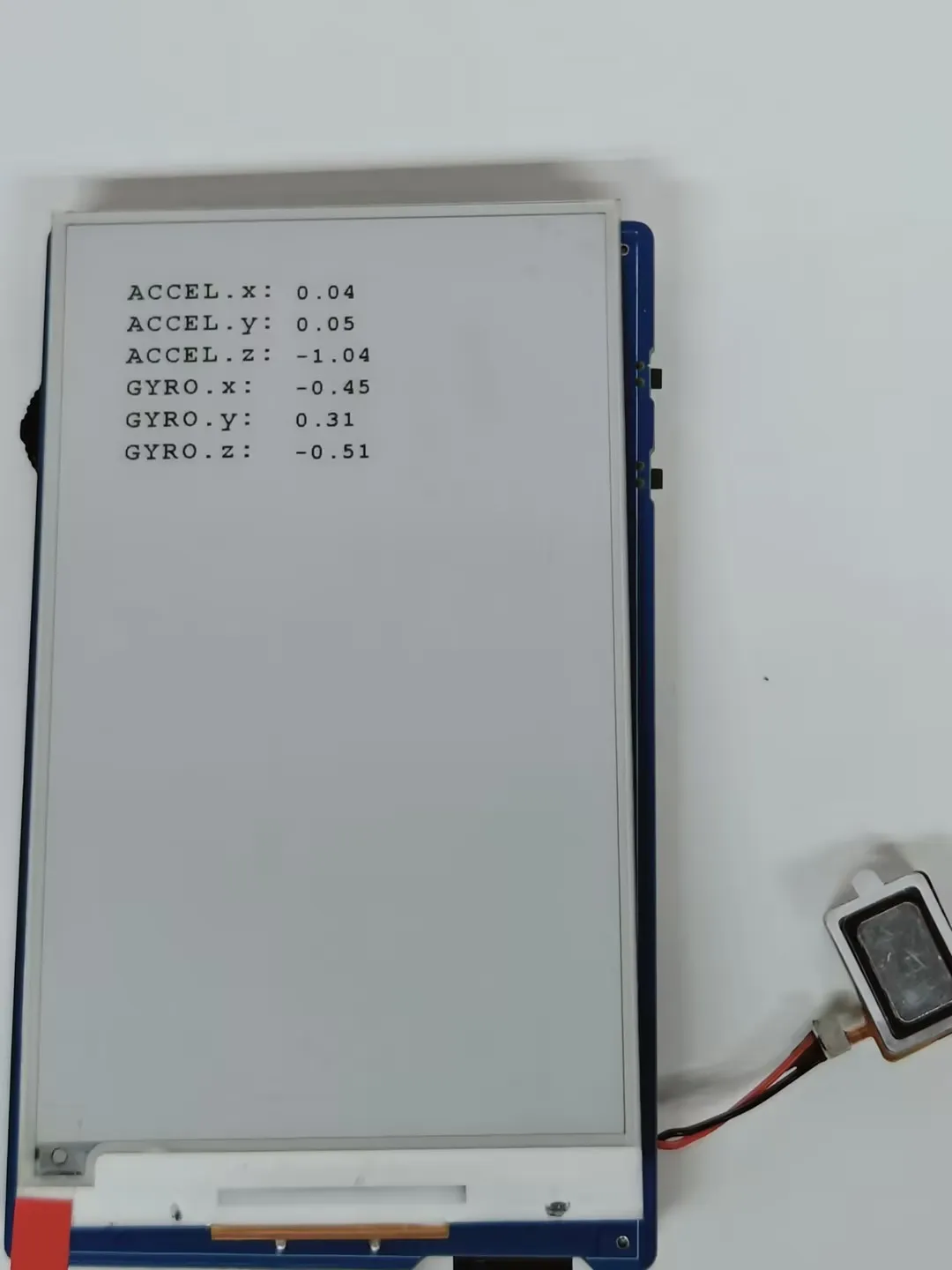
Operation Result
The e-Paper display partially refreshes to show 6-axis gyroscope sensor data.
06_I2C_PCF85063
Demo Description
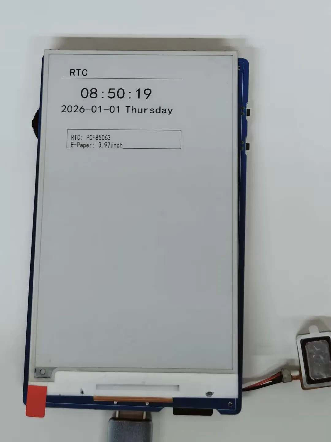
- This example uses the onboard PCF85063 RTC chip to dynamically display time on the 3.97inch e-Paper screen, combining it with the I2C interface RTC real-time clock module.
Hardware Connection
- Connect the development board to the computer
Code Analysis
epaper_port_init();/EPD_Init();/EPD_Clear();calling EPD_Display_Partial for a partial e-Paper refresh after drawing values: Initializes the e-Paper's low-level hardware ports and driver parameters, clears the screen to a white background.i2c_master_init();: Initializes the I2C bus, providing a communication link for configuring and reading time from the PCF85063 RTC module.PCF85063_init();: Initializes the PCF85063 RTC module, completing the default clock register configuration.PCF85063_GetTime();/PCF85063_SetTime();: Reads the RTC's current time and sets the default time.xTaskCreate(rtc_test_task, "rtc_display", 4096, NULL, 5, NULL);: Creates a FreeRTOS task to execute the RTC time reading and display logic.display_time_on_epaper(): After drawing the values, callsEPD_Display_Partialfor a partial refresh to display the data.
Operation Result
The e-Paper display partially refreshes to show the time.
07_I2C_SHTC3
Demo Description
- This example uses the onboard SHTC3 temperature and humidity sensor to dynamically display temperature and humidity data on the 3.97inch e-Paper display.
Hardware Connection
- Connect the development board to the computer
Code Analysis
epaper_port_init();/EPD_Init();/EPD_Clear();calling EPD_Display_Partial for a partial e-Paper refresh after drawing values: Initializes the e-Paper's low-level hardware ports and driver parameters, clears the screen to a white background.i2c_master_init();: Initializes the I2C bus.i2c_shtc3_init();: Initializes the SHTC3 temperature and humidity sensor module.xTaskCreatePinnedToCore(i2c_SHTC3_loop_task, "i2c_SHTC3_loop_task", 3 * 1024, NULL , 2, NULL,0);: Creates a FreeRTOS task.i2c_SHTC3_loop_task(): Obtains temperature and humidity values and prints them, then callsEPD_Display_Partialfor a partial refresh to display the data.
Operation Result
The e-Paper display partially refreshes to show the temperature and humidity.
08_ESP32-S3_e-Paper-3.97
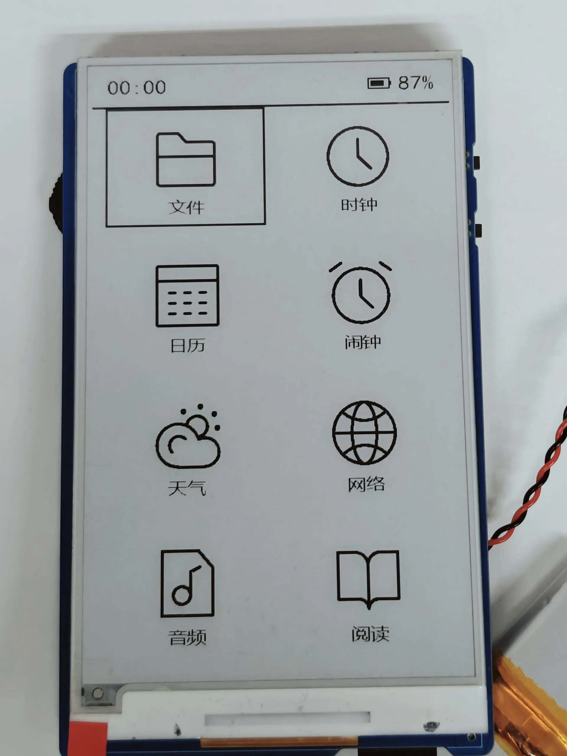
Demo Description
- This example integrates eight core functions: file browser, clock, calendar, alarm, weather, network configuration, audio playback, and e-reader, implementing a menu-based interactive interface and button control for the e-Paper.
Hardware Connection
- Connect the development board to a computer using a USB cable.
- Copy all files from the TF card folder in the example program to the root directory of a TF card.
- Insert the TF card module.
Battery Life
- In clock mode, a 1500mAh battery can operate for over 15 days.
Code Analysis
- In
app_main(), the initialization of NVS, TF card, I2C peripherals (sensors/clock/audio), buttons, and the e-Paper is completed. Configuration (WiFi enable, operating mode) is loaded from NVS, and corresponding tasks are created based on the mode. void user_Task(void *arg)is responsible for drawing the e-Paper main menu (8 function icons + text), responding to button events (up/down selection, confirm to enter subpage, global refresh, shutdown), managing e-Paper low-power states (sleep after 5 seconds of inactivity, soft shutdown after 10 minutes of inactivity), and refreshing the top status bar (time/battery/WiFi status).file_browser_task();File browsing module.page_clock_show();Clock module.page_calendar_show();Calendar module.page_alarm_menu();Alarm module.page_weather_city_select();Weather module.page_handle_network_key_event();Network configuration module.page_audio_main();Audio playback module.page_fiction_file();E-reader module.
Operation Result
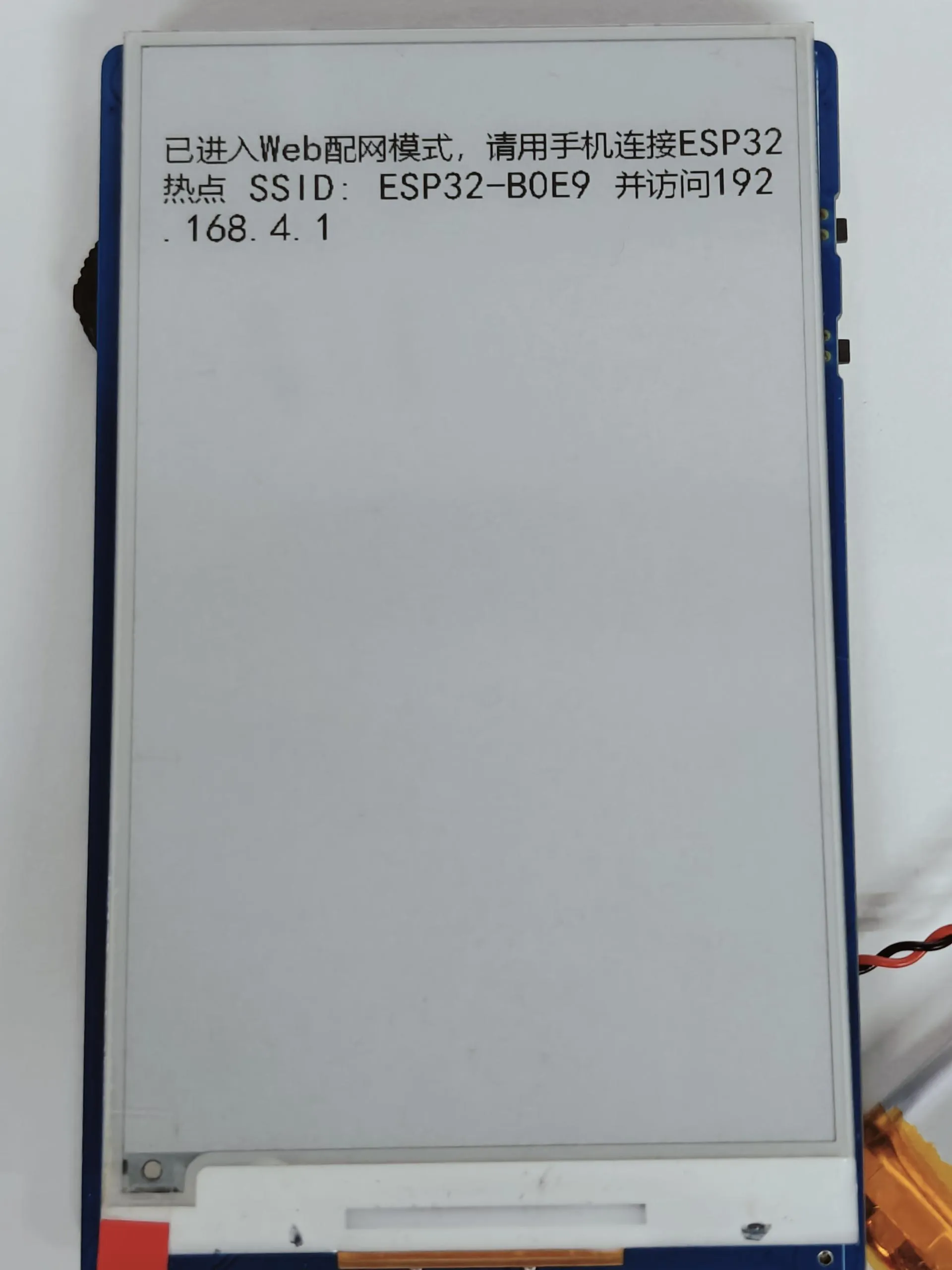
After the program is flashed, it enters the network configuration interface. Configure the network by connecting to the WiFi name displayed on the e-Paper.
After network configuration is complete, it enters the main page. Control is via the rotary encoder button and the BOOT and PWR side buttons. The e-Paper automatically sleeps after 60 seconds of inactivity and soft shuts down after 10 minutes of inactivity.
File Browser Module
- Reads all directories and files on the TF card. Only folders, .txt text files, and audio files can be opened; other format files cannot be opened.
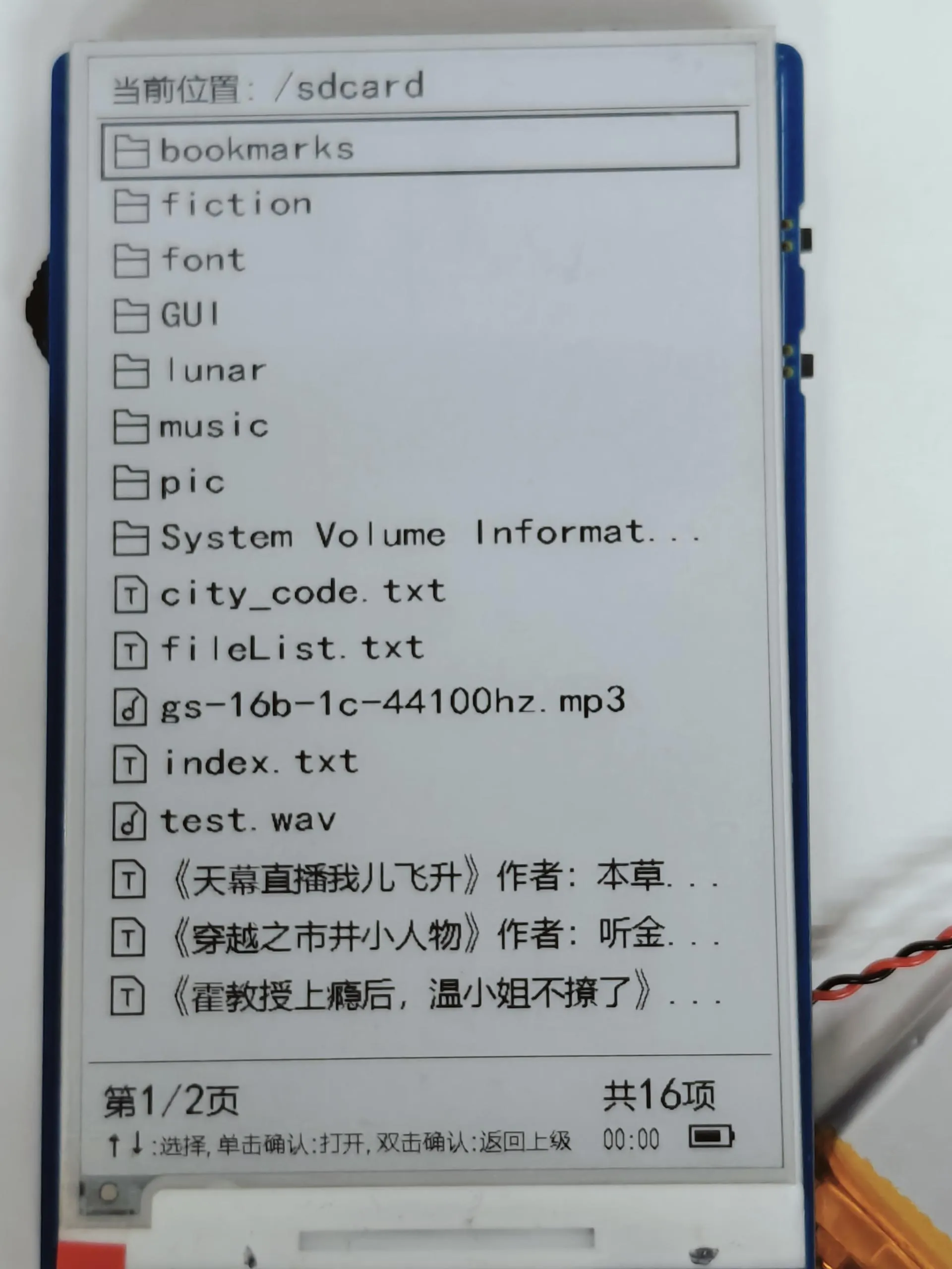
- Use the rotary encoder up/down (↑↓) to select files/directories. A single click confirms to enter/open.
- Double-click confirm or press Boot to return to the previous directory. Long press the middle of the rotary encoder to perform a global refresh.
- Reads all directories and files on the TF card. Only folders, .txt text files, and audio files can be opened; other format files cannot be opened.
Clock Module
- Refreshes and displays temperature, humidity, time, and battery level.
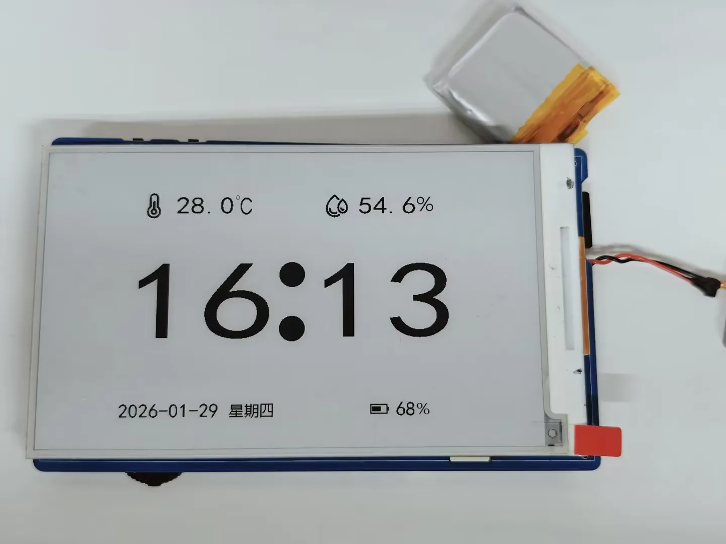
- Supports timezone selection function: Click confirm to enter the timezone selection interface. The e-Paper displays operation prompts. Use the rotary encoder up/down (↑↓) to select the timezone, then click confirm to apply.
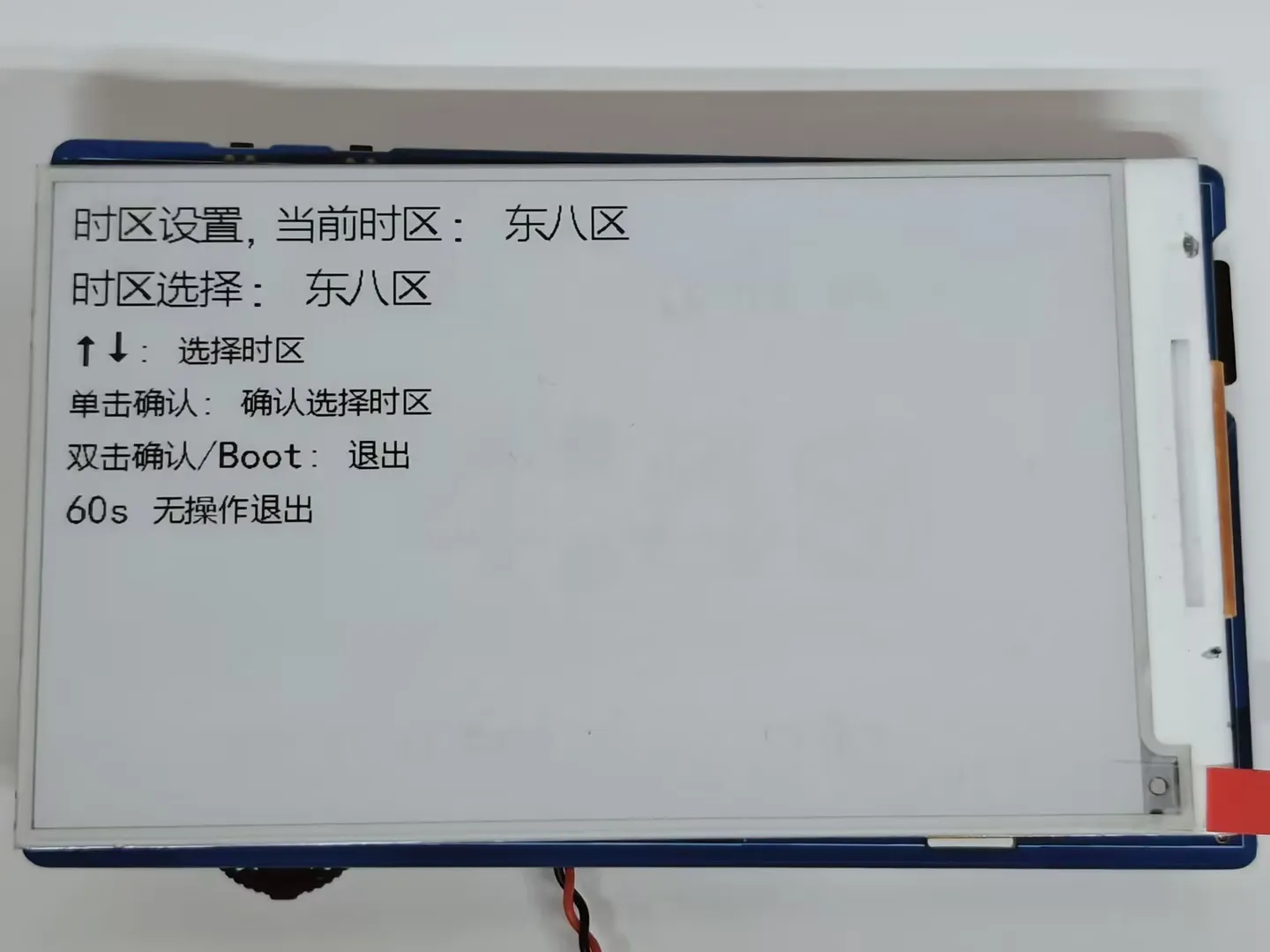
- Refreshes and displays temperature, humidity, time, and battery level.
Calendar Module
- Refreshes and displays the calendar (based on the domestic API in China, which may load slowly for users outside China), including the Gregorian date, Chinese lunar date/solar term/festivals. The current date is highlighted.
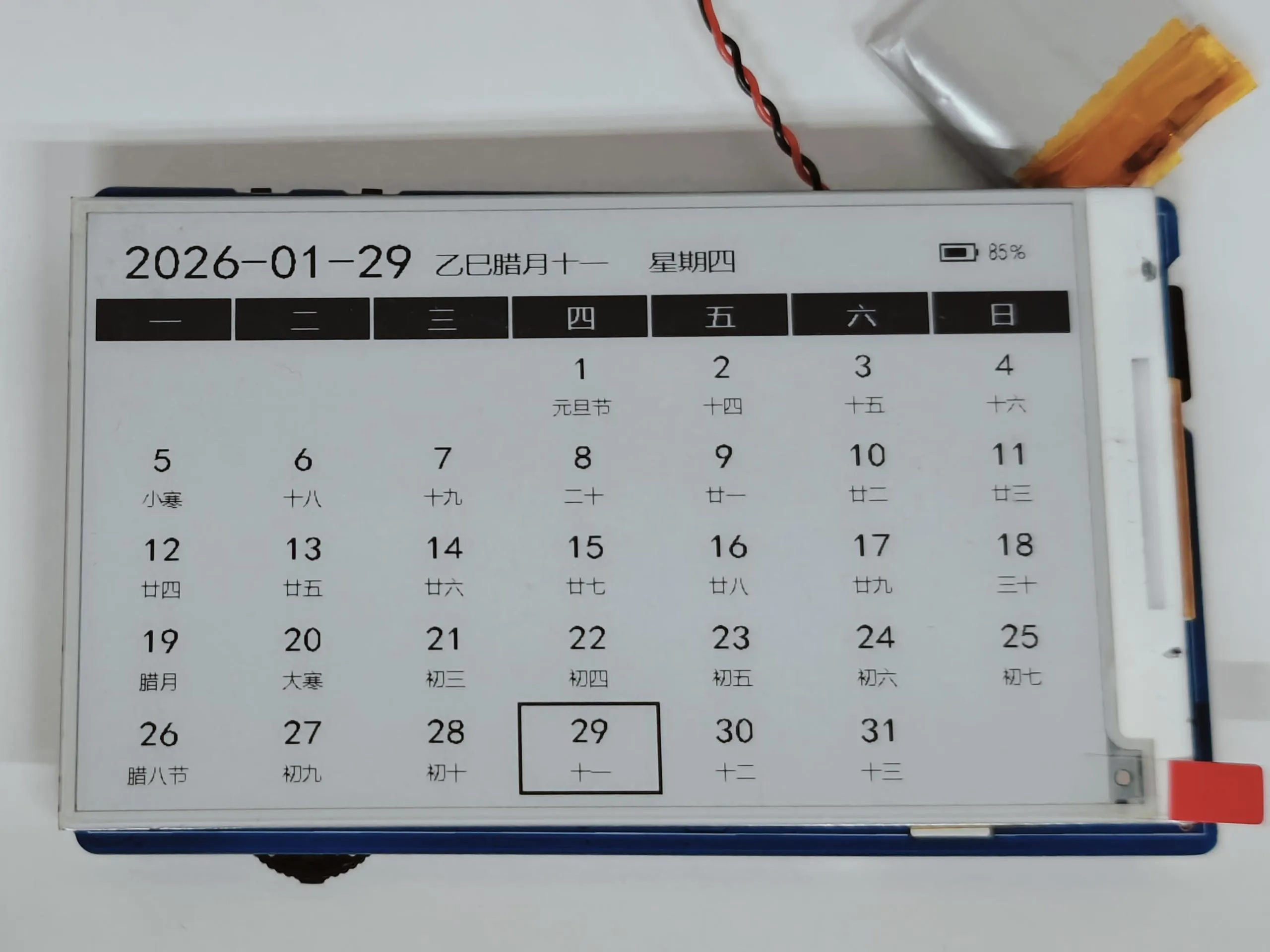
- Supports manual refresh: Long press the middle of the rotary encoder to fetch the latest date data from the network again. It automatically updates once per day.
- Low power and wake-up rules: Automatically shuts down after 10 minutes of inactivity. By default, the RTC wakes up once every hour. If an alarm is detected as set on the current page, it changes to waking up once per minute.
- Refreshes and displays the calendar (based on the domestic API in China, which may load slowly for users outside China), including the Gregorian date, Chinese lunar date/solar term/festivals. The current date is highlighted.
Alarm Module
Main interface of the alarm module, supporting up to 5 alarm settings.
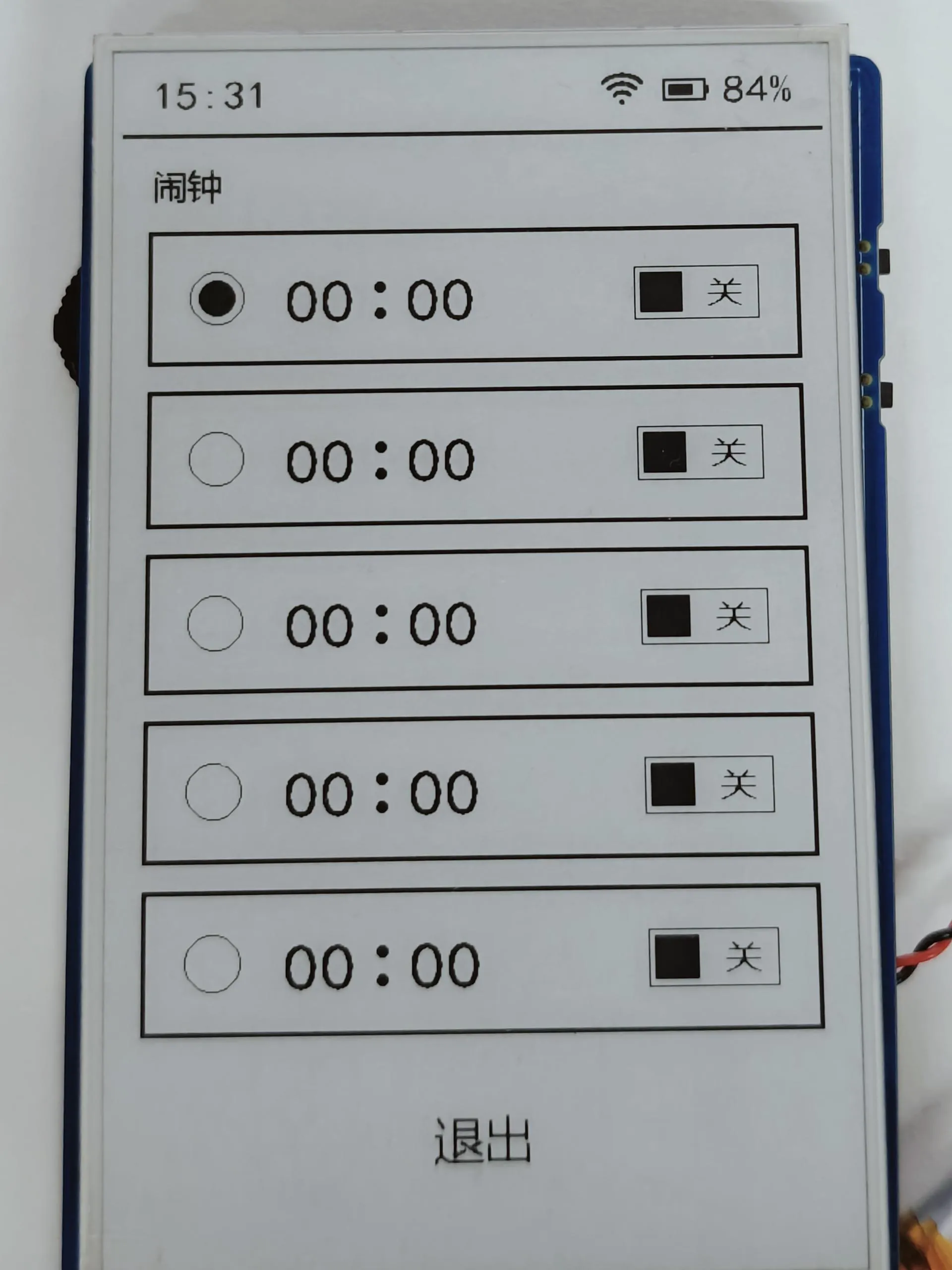
After deleting an alarm, the time resets to 00:00 by default and the status is OFF. Click confirm to enter alarm editing mode. Use the rotary encoder up/down (↑↓) to select the content to edit (hour/minute/switch).
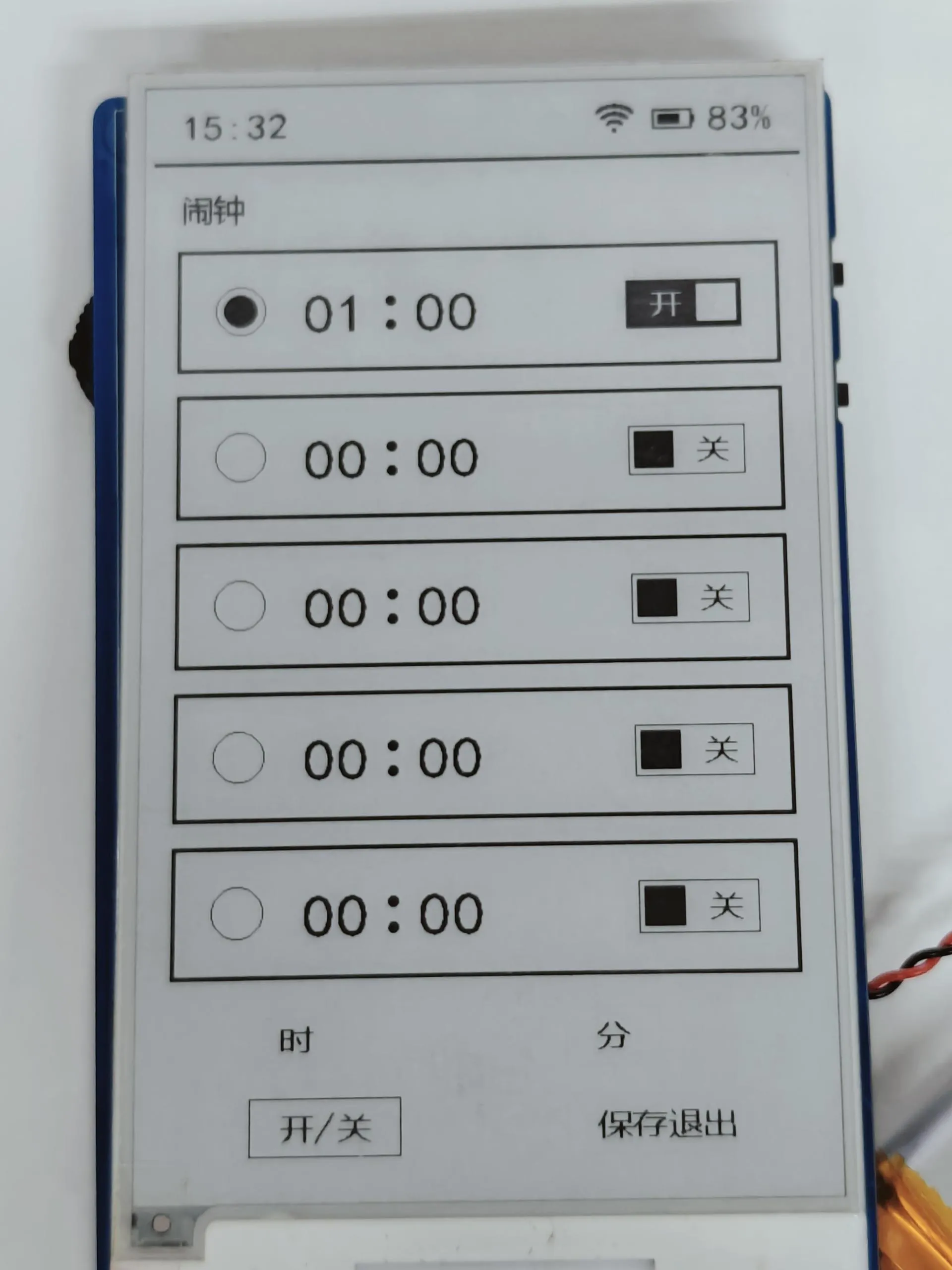
Hour/Minute editing: Click confirm to enter value adjustment. The rotary encoder up/down (↑↓) buttons allow single-step adjustment or continuous adjustment when held. Switch editing: Click confirm to toggle the ON/OFF state once. Double-click confirm or press Boot to exit editing mode.
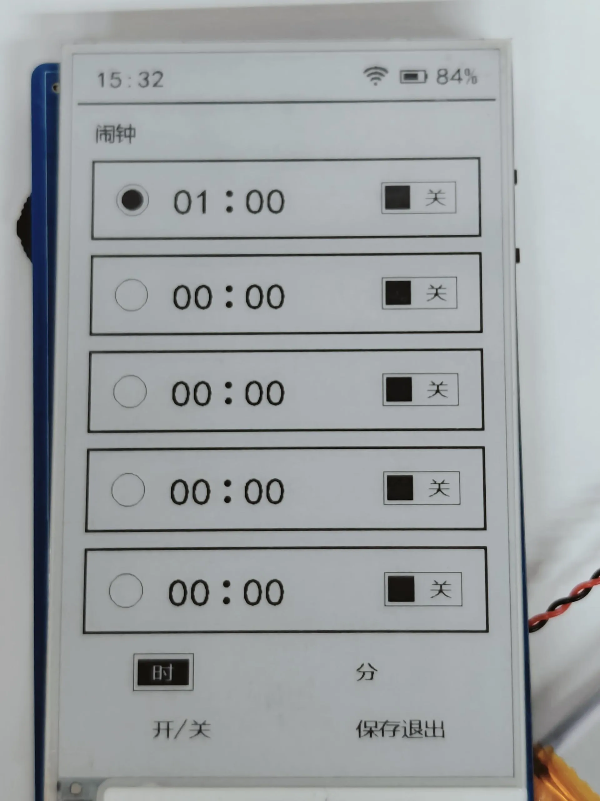
Alarm trigger: When the set alarm time arrives, it automatically plays a built-in audio. Press any button to stop playback. Double-click confirm or press Boot to exit the alarm module and return to the main page.
Weather Module (Requires WiFi connection to be enabled first. It uses a Chinese weather service API and code tables, and is currently in the testing phase for adaptation to an English API.)
- Main interface of the weather module, showing the date, temperature/humidity, and weather information for the next 4 days.
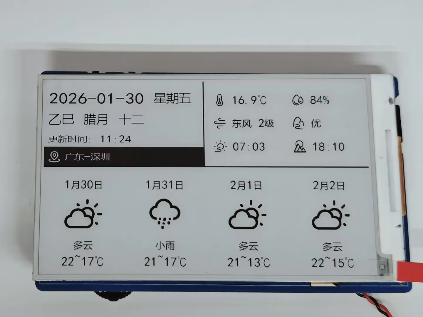
- Automatically updates weather data at four fixed times daily (4:00, 9:00, 14:00, 20:00). Long press the rotary encoder to manually fetch the latest weather from the network.
- Automatically shuts down after 10 minutes of inactivity. By default, the RTC wakes up once every hour. If an alarm is detected as set on the current page, it changes to waking up once per minute.
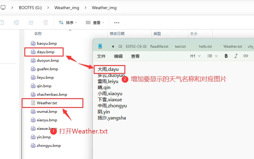
- The weather module's icon files are stored in: sdcard\Weather_img\Weather_img. Supports adding/modifying weather images:
- Add new weather images in the sdcard\Weather_img\Weather_img folder.
- Open Weather.txt, add the name to display and the corresponding image.
- Main interface of the weather module, showing the date, temperature/humidity, and weather information for the next 4 days.
Network Configuration Module
- Supports turning WiFi ON/OFF and re-configuring the network. When WiFi is OFF, only "Turn ON WiFi" and "Return to Main Menu" are displayed. When WiFi is ON, "Turn OFF WiFi", "Re-configure Network", and "Return to Main Menu" are displayed.
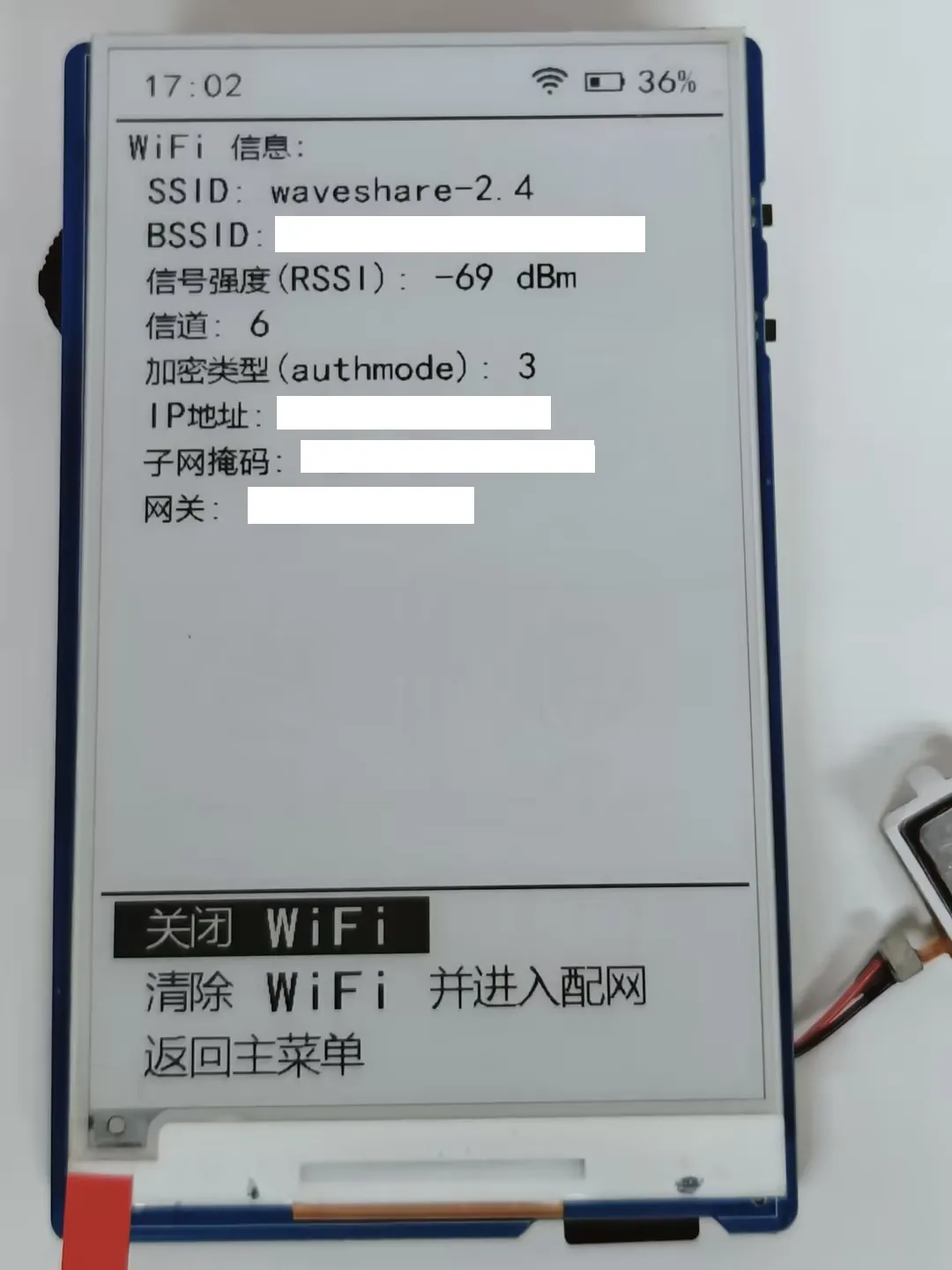
- After selecting network configuration, it enters STA mode. In this mode, auto-shutdown is not triggered; only the e-Paper enters sleep state, while the ESP32 continues to work. Connect a device to the WiFi name displayed on the e-Paper to complete the configuration.
- It attempts to connect to the configured WiFi for 30 seconds, during which no other operations are possible. If the connection fails, it exits configuration. Upon successful connection, it automatically obtains an IP address, and the e-Paper prompts that configuration was successful.
- Supports turning WiFi ON/OFF and re-configuring the network. When WiFi is OFF, only "Turn ON WiFi" and "Return to Main Menu" are displayed. When WiFi is ON, "Turn OFF WiFi", "Re-configure Network", and "Return to Main Menu" are displayed.
Audio Playback Module
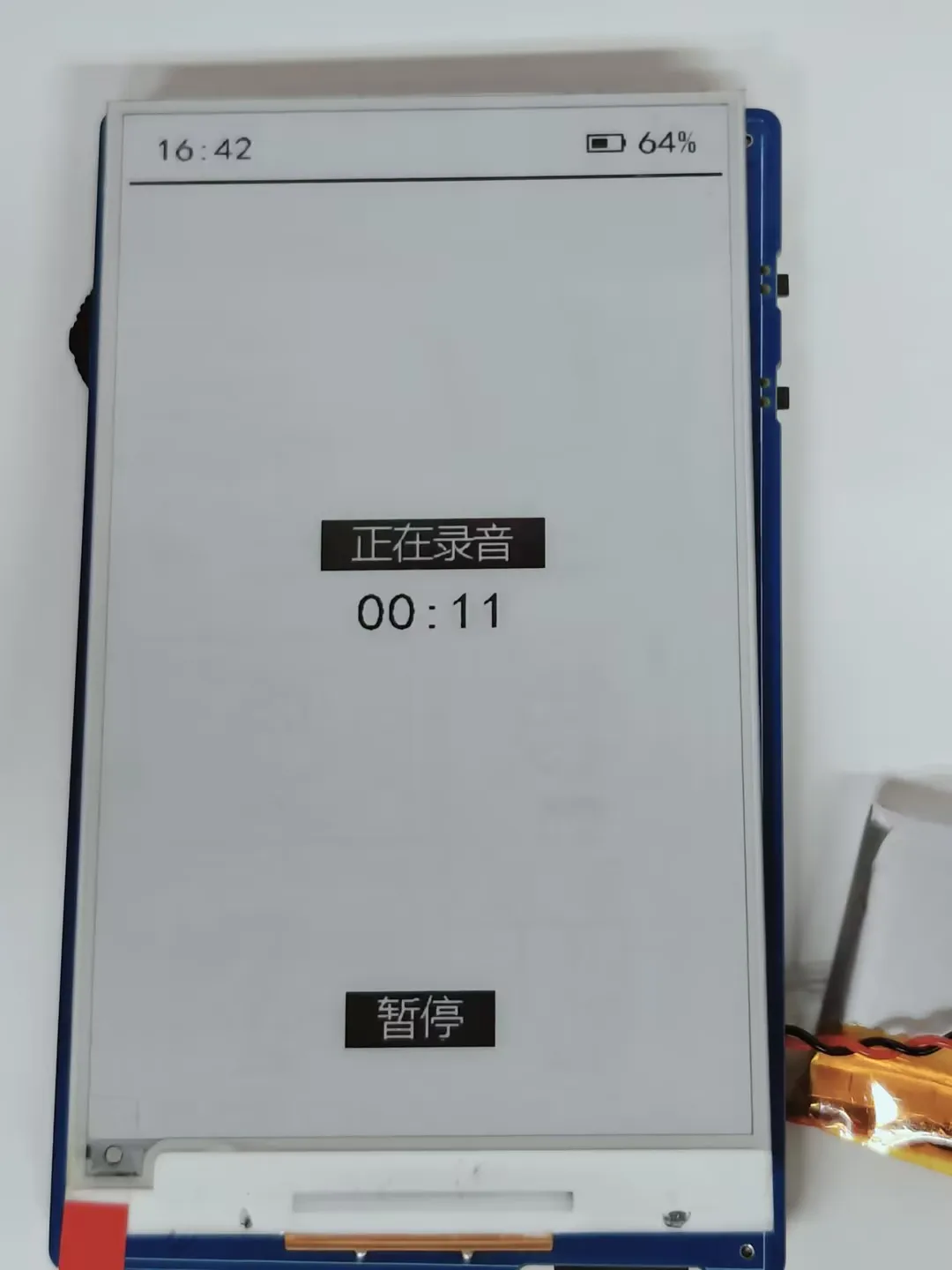
- Supports three audio modes: Built-in audio, TF card audio, and Recording. Use the rotary encoder up/down (↑↓) to select the mode, then click confirm to enter. TF card audio reads files from the music folder in the TF card root directory. Recorded audio files are also automatically saved to this folder.
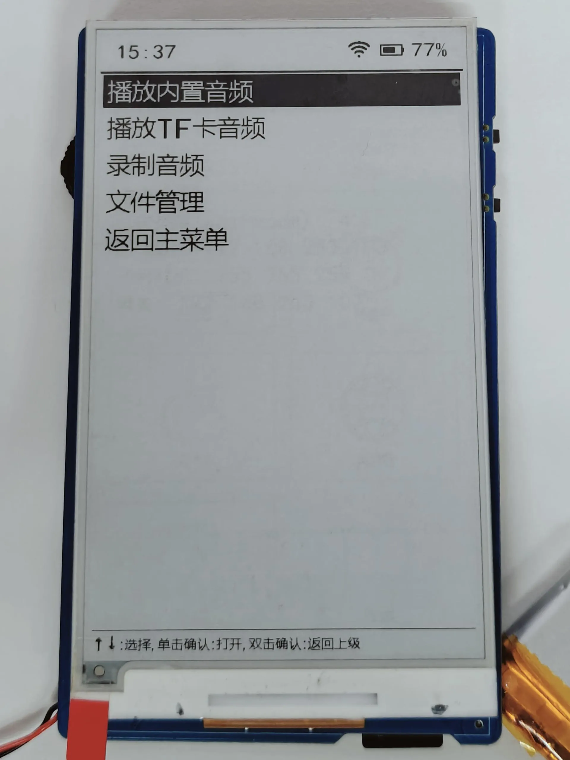
- For built-in audio, click confirm to play directly. For recording mode, click confirm to start recording immediately. In TF card audio mode, click confirm to select and play an audio file. There is no volume control function.
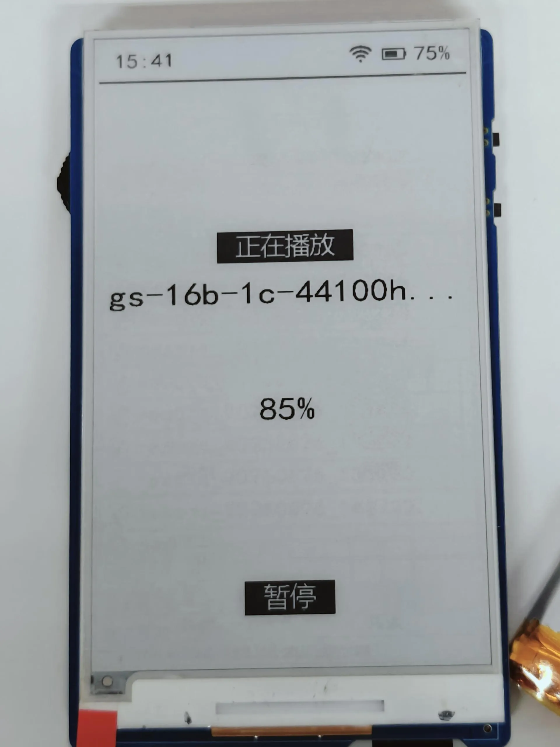
- After selecting an audio file, click confirm to enter the operation selection interface. Double-click confirm or press Boot to return to the previous level. Long press the middle of the rotary encoder performs a global refresh.
- Supports three audio modes: Built-in audio, TF card audio, and Recording. Use the rotary encoder up/down (↑↓) to select the mode, then click confirm to enter. TF card audio reads files from the music folder in the TF card root directory. Recorded audio files are also automatically saved to this folder.
E-reader Module
Main interface of the e-reader module.
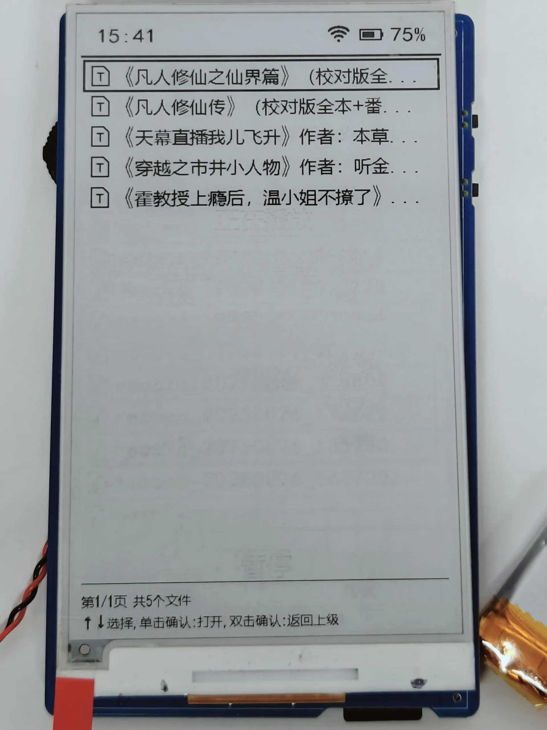
Reads .txt text files from the fiction folder in the TF card root directory. Use the rotary encoder up/down (↑↓) to select a file, then click confirm to start reading. While reading, use the rotary encoder up/down (↑↓) to turn pages.
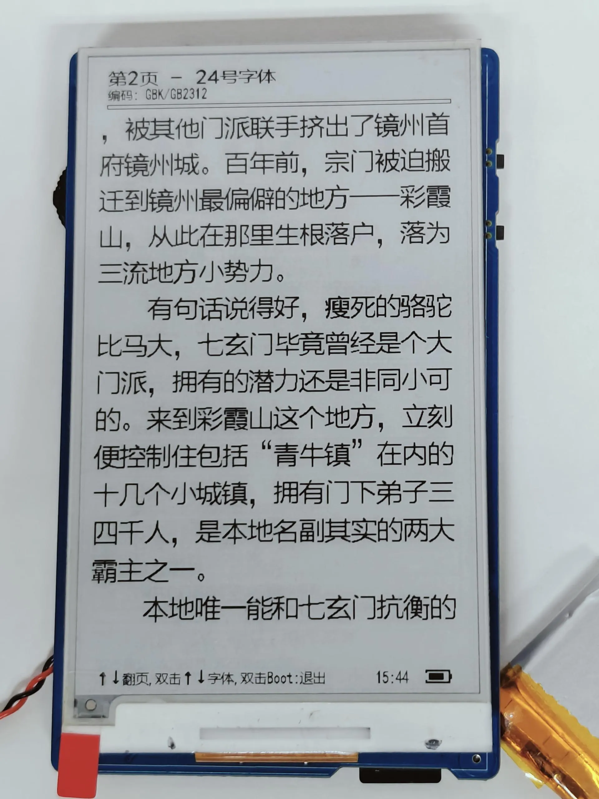
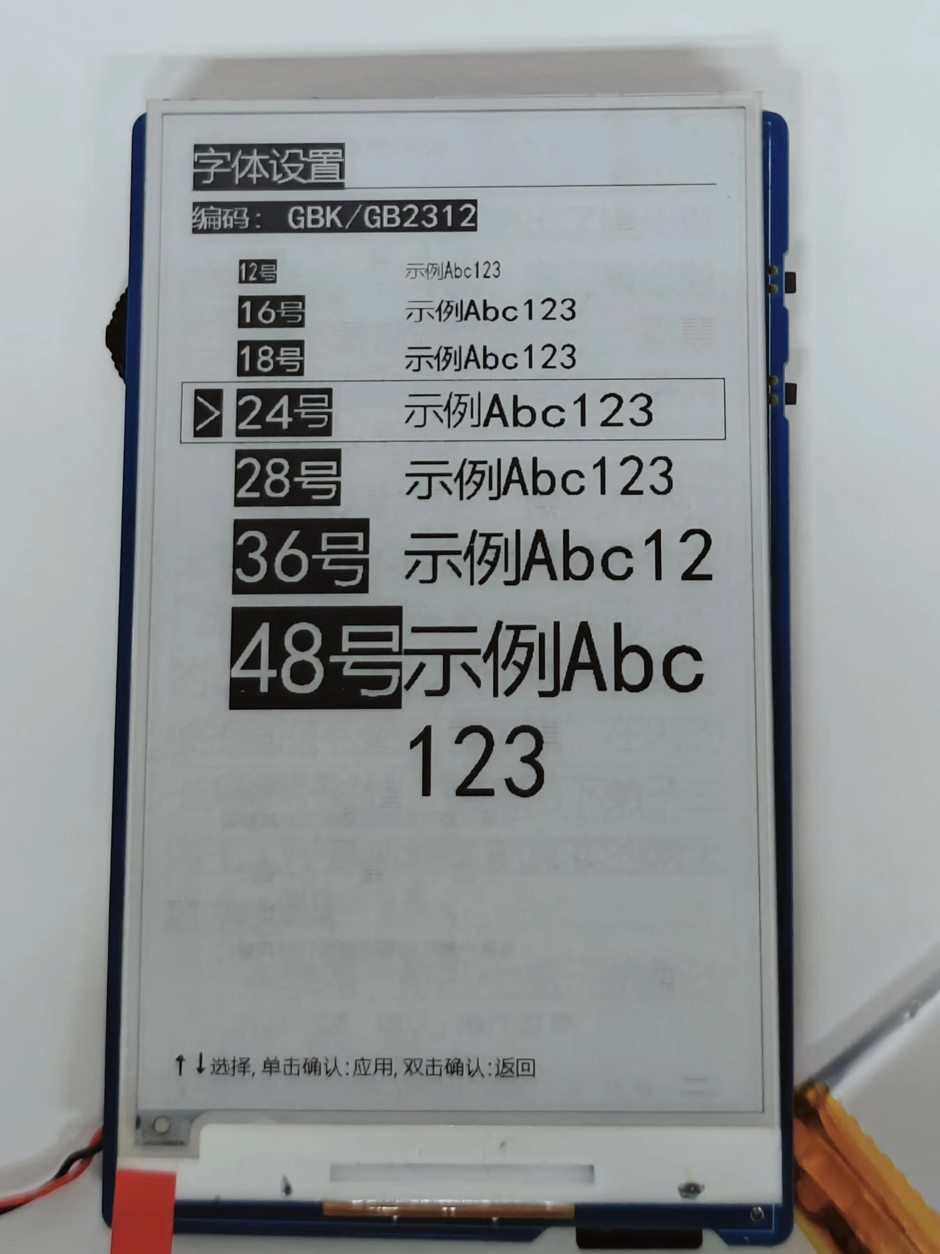
Double-click the rotary encoder to enter the font selection interface. Click confirm to select a font and apply it.
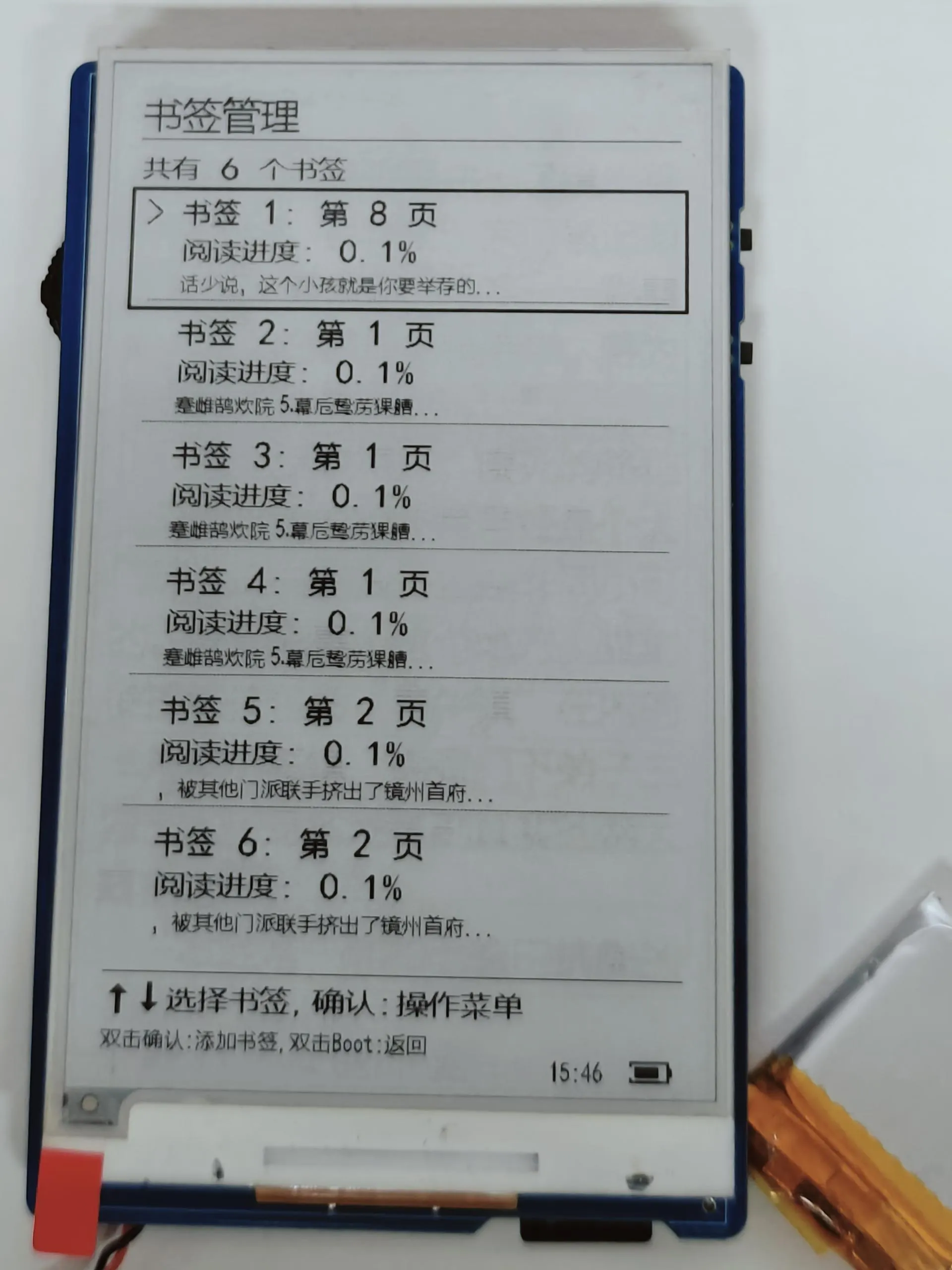
Click the rotary encoder to enter the bookmark management interface. Click again to perform a bookmark operation. Double-click confirm to add a bookmark. Reading progress and bookmarks are automatically saved to the bookmarks folder on the TF card.
System Settings Module
- Entry method: On the main page, long press the Boot button to enter the settings interface. Use the rotary encoder up/down (↑↓) to select a function item. Click confirm to view. Double-click confirm or press Boot to return to the main page.
- Currently supports two major functions: Memory Display (shows the device's current memory status) and QMI8658 6-axis Status Display (real-time display of acceleration, angular velocity, etc.).
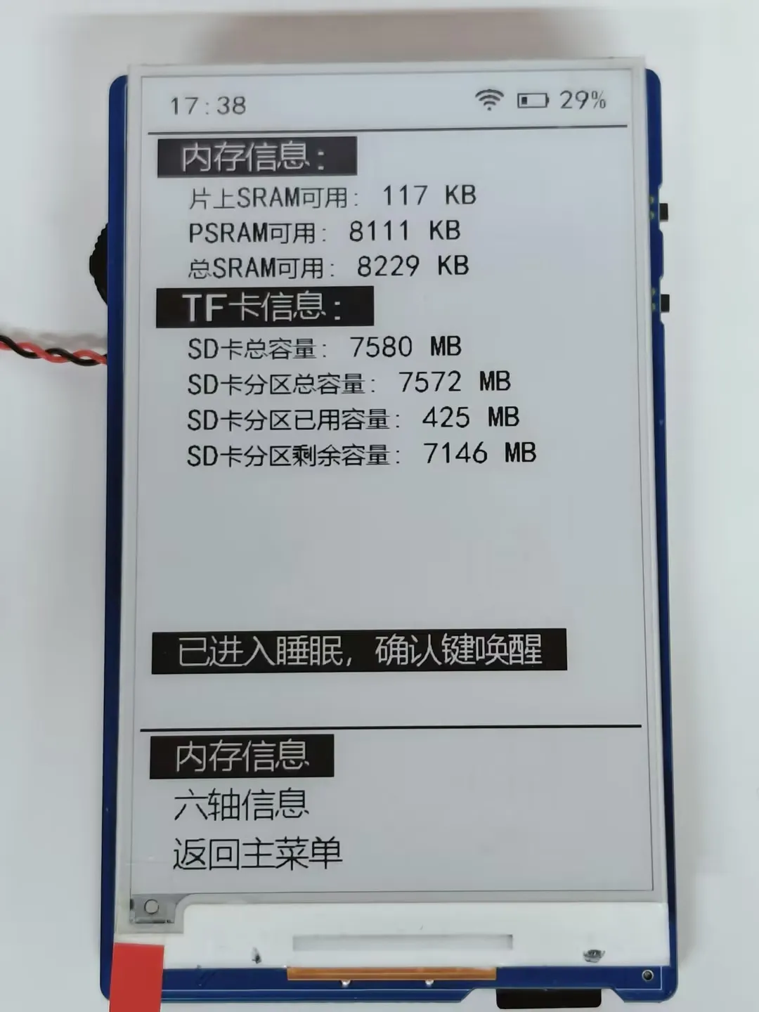
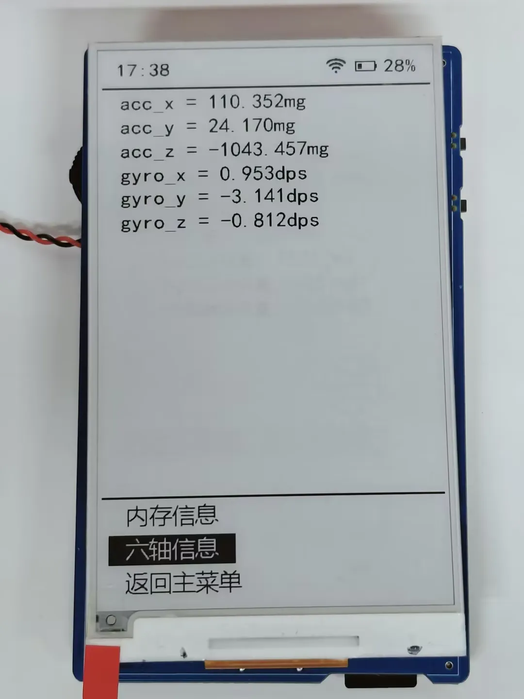
- Supports global refresh: Long press the middle of the rotary encoder to perform a global refresh of the e-Paper, following the low-power rules of 60-second sleep and 10-minute shutdown.
System Power ON/OFF
- On the main page, double-click the Boot button to shut down the system.
- Long press the Power button for 4 seconds to power on the system. The e-Paper refreshes and displays content.
Resources
1. Hardware Resources
Development Board Design File
- Schematic: ESP32-S3-ePaper-3.97-Schematic.pdf
2. Technical Manuals
Official ESP32-S3 Chip Manuals
Onboard Component Datasheets
3. Demo
4. Software Tools
- Arduino:
- VScode:
- Firmware Flashing Tool:
Support
Monday-Friday (9:30-6:30) Saturday (9:30-5:30)
Email: services01@spotpear.com
[Tutorial Navigation]
- ESP32-S3-ePaper-3.97
- Working with Arduino
- Setting Up Development Environment
- 1. Installing and Configuring Arduino IDE
- 2. Installing Libraries
- 3. Arduino Project Parameter Settings
- Demo
- ESP-IDF
- Setting up the Development Environment
- Demo
- Resources
- Support