- sales/support
Google Chat:---
- sales
+86-0755-88291180
- sales01
sales@spotpear.com
- sales02
dragon_manager@163.com
- support
tech-support@spotpear.com
- CEO-Complaints
zhoujie@spotpear.com
- Only Tech-Support
WhatsApp:13246739196
- Purchase/Shipping/Refund
WhatsApp:13424403025
UGV-Rover-PT-Raspberry-Pi-AI-Kit User Guide
Introduction
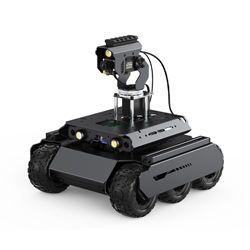
UGV ROVER, a 6-wheel 4WD AI robot, features a dual-controller structure. The ESP32 slave computer controls the motor PID, IMU sensors, OLED screen, servo, LED ON/OFF, and so on, which greatly reduces the IO resources for the host computer and provides high-performance communication interfaces. Also, the host controller supports Raspberry Pi 4B/5, offering high computational power and advanced features such as specified strategies.
It is high-strength and more durable as the robot's body is made of a 2mm thick aluminum alloy casing. In addition, it adopts soft and anti-slip rubber tires paired with four gear motors with encoders, functioning closed-loop speed control and reducing vibration. It enjoys a more excellent performance in movement with a maximum speed of 1.3m/s. With the built-in 3S lithium battery UPS power module, it offers robust and long-lasting motivation, supporting continuous use while charging to meet long-term development and usage requirements.
The Raspberry Pi 4B/5 paired with a USB camera provides users with a smooth visual experience through real-time footage with high frame rates and low latency. Users can enjoy capturing different wonderful moments through functions such as taking photos and recording videos. Additionally, various feedback information from the robot, including battery voltage and CPU usage, is displayed in real-time through a web application, allowing users to monitor the robot's status in real-time.
The robot's visual system is equipped with a 2DOF(degrees of freedom) high-torque flexible pan-tilt and a 160° ultra-wide-angle 5-megapixel camera, providing users with a wide field of view, flexible viewing angles, and various AI machine vision functions. The high-brightness LED spotlight next to the pan-tilt ensures clear visibility even in low-light environments. Additionally, the design with Picatinny rails allows users to easily expand more tactical accessories, further enhancing the robot's functionality.
To enable users to fully leverage the potential of this robot, we provide online documentation and tutorials, including a JupyterLab web application. Whether you're a beginner in robotics technology or an experienced developer, you can delve into learning, understanding, and creating step by step through these resources.
Features
- High-performance Dual Controller: the slave computer is ESP32, responsible for precise motor PID control and multiple sensor readings; the host computer Raspberry Pi 4B/5 offers high computational power. The two-layer architecture makes the robot run more efficiently.
- Open-source Code: The host controller is based on the latest version of the Raspberry Pi system (Debain Bookworm) development, WEB applications based on Flask, Python language, the software platform is all open source, easy for users to learn and secondary development.
- Rich Tutorials: Offers rich JupyterLab, graphic and video tutorials covering various functionalities to help users quickly get started and use the robot, thereby accelerating the realization of innovative applications.
- Omnidirectional Workspace: The base, with 360° rotation, combined with flexible joint movements, creates a workspace with a diameter of up to 1 meter, enabling versatile movement in all directions.
- Wide Viewing Angle: Equipped with a 2-degree-of-freedom, high-torque, flexible pan-tilt that provides a wide 360° viewing angle horizontally, and a 5-megapixel camera with a 160° wide-angle, it captures a wider range of images.
- Robot Vision: Integrated with machine vision functions such as color, object and gesture recognition, face and motion detection, it can be extended for more applications.
- Abundant Interaction: Real-time video streaming, digital zoom, photo, video, and other functions, and WEB application of real-time video functions and robot information displayed on the screen to improve the user interaction experience.
- Cross-platform Support: Supports cross-platform remote control without the need to install an app. You can follow tutorials to implement remote control beyond the local network using solutions such as Pgyer, Cpolar, LocalTunnel, and others.
- Expandability: features a mounting plate and Picatinny rails, facilitating the attachment of additional tactical accessories. On the hardware side, there are spare interfaces available for LED lights, which can be used for expanding peripherals such as water guns. Additionally, the product can be expanded with 4G or 5G modules, enabling users to explore more possibilities.
- Durable Structure: The 2mm thick aluminum alloy case provides outstanding structural strength and durability.
- High-Performance Drive Motors: Equipped with four motors with encoders, enabling closed-loop speed control. With a maximum speed of 1.3m/s, it delivers robust power.
- All-Drive and High-Quality Tires: Featuring a four-wheel drive system paired with soft, non-slip rubber tires, ensuring excellent traction and stability on various terrains.
- Long Battery Life: Utilizing a 3S lithium battery UPS power system, it supports continuous use while charging, ensuring long-lasting endurance.
Assembly Tutorial
To be continued...
User Guide
Notices
Please read the following content before using:
- 3x 18650 lithium batteries are required and need to be purchased separately to ensure normal operation of the 3S UPS module, a battery with a high discharge rate is recommended. And a Raspberry Pi is required and needs to be installed independently if you are using ACCE version.
- When connecting the battery for the first time, pay attention to whether the LED light is on on the battery module. If the LED light is on, it means that the positive and negative electrodes of the battery are connected inversely. If the battery is not connected inversely, the LED light will not be on. Do not charge the battery when it is reversed, otherwise it may cause an explosion.
- This product can not suffer severe impact and is not waterproof.
- Do not manually rotate the wheels. For high-gear reduction motors, manually rotating the wheels may cause damage to the gearbox.
First Time Use
The SD card shipped with the product is an image with the software already configured, and the SD card can be used by plugging it into the Raspberry PI.
After turning on the power switch, the product will be initialized, and the OLED screen will display a series of initialization contents; Raspberry PI will automatically establish a hot spot during startup, and the ip address will be displayed on the OLED screen after the main program of the project automatically runs. The content displayed on the OLED screen after startup is completed is as follows:
- The first line E: the IP address of the Ethernet port for remotely accessing the Raspberry Pi. "No Ethernet" means that the Raspberry Pi has no Ethernet cable connection.
- The second line W: In AP mode, the robot will automatically establish a hotspot and display the default IP: 192.168.50.5. In STA mode, the robot will connect to the IP address assigned by the known WIFI; The IP address displayed can be used to wirelessly connect to the Raspberry PI.
- The third line F/J: Network port number, "5000" is used to access the main program control page of the product, "8888" is used to access the JupyterLab page.
- The fourth line AP: means the WIFI is in AP mode, and the time means the usage period of the robot, the value in dBm represents the signal strength RSSI of WIFI in STA mode.
You can use a mobile phone or PC to access this hotspot automatically created by the product, the name of the hotspot is AccessPopup, and the password of the hotspot is 1234567890. After connecting, open the browser, enter the default IP address of the device in AP mode (the address will be displayed at line W on the OLED screen), that is, enter 192.168.50.5:5000 in the URL bar to access the control interface of the main program of the product.
Note: If the robot doesn't automatically establish a hotspot after powering on, please refer to #Images_Flashing and re-flashing the image.
Network Configuration
The network needs to be configured in the JupyterLab interface, and there are two methods to open JupyterLab interface:
- You can click on
 in the control interface of the main program to enter the JupyterLab interface.
 - You can access the IP address of the robot IP address: 8888 to enter the JupyterLab interface. The factory default is still AP mode, so enter 192.168.50.5:8888 in the URL bar to open the JupyterLab page.
First Time to connect a known WiFi
The default WiFi mode of the robot is AP mode, you can refer to the following steps to switch to STA mode and connect to known WiFi:
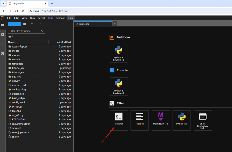
1. After accessing the JupyterLab interface, click the "Terminal" at the bottom of the page, and enter the following command to enter the project folder.
bash
2. You can see that the current location is ~/ugv_rpi, then go to the WIFI Configuration Tool folder and enter the following command and then enter.
cd AccessPopup/
3.Enter the following command to grant executable permission to the WiFi configuration script in the AccessPopup folder:
sudo chmod +x installconfig.sh
4. Run the WiFi configuration script by the following command:
sudo ./installconfig.sh
5. After running the script, you will see the following interface. Here you need to set up a connection to a known WIFI, so enter "5" and press Enter to set up a new WiFi Network connection.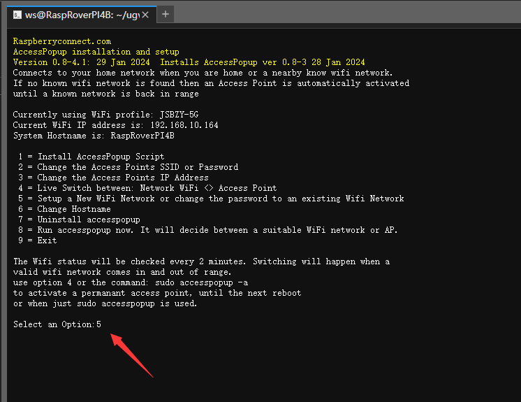
6. Then it will jump to Add or Edit WIFI Network interface, wait for a while, this page will output the WIFI names near the current device, as shown below, there is a serial number before each WIFI, enter the serial number of the WIFI you want to connect and then enter.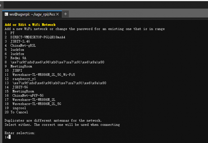
7. Next, enter the WIFI password to be connected and enter, the product will connect to the set WIFI hotspot. After successful connection, you can see the IP address change of the W line on the OLED screen of the product.
8. The JupyterLab page has to be accessed again with the IP address of the W line on the current OLED screen because the IP address has changed. The product is in STA mode after a successful connection and enters the JupyterLab page with the same screen as before, as shown below, press any key to continue.
9. And then you can press "9" and press Enter to exit the WiFi configuration script.
After connecting to a known WIFI successfully, if the product runs out of the range of the known WIFI when it is powered on thereafter, the product will automatically establish a hotspot, and the hotspot will still be AccessPopup by default.
WIFI Mode Switching
- Switch STA mode to AP mode:
Switch to AP mode to establish a hotspot when connected to a known WIFI, open Terminal on the JupyterLab page, enter bash to go to the project folder, and then enter the following command to establish a hotspot.
sudo accesspopup -a
- To switch back from AP mode to STA mode:
To have the device switch from AP mode to STA mode after a known WIFI configuration has been performed, enter the following command to reconnect to a known WIFI.
sudo accesspopup
Note: As long as the WIFI mode is switched, the control interface of the main product program and the IP address of the JupyterLab page have to be refreshed accordingly to be accessible.
Delete Known WIFI
1. Open a "Terminal" on the JupyterLab interface, enter bash to enter the project folder.
bash
2. Then, use the following command to check all network connections:
nmcli connection show
3. Use the following command to delete a known WiFi connection: replace <connection_name> with the name of the WiFi network you want to delete:
sudo nmcli connection delete <connection_name>
Note: If you delete the known WIFI connected to the current device, the product will automatically create a hotspot after deletion, in this case, the hotspot is still AccessPopup by default, and the IP address that accesses the JupyterLab page must be refreshed before it can be used.
Product Tutorial
Product Initialization
Images Flashing
Note: This section is not required, only when the system image of the product is updated or the upper computer of the product needs to be restored to the factory system image, the image needs to be re-burned for the Raspberry Pi.
The official Raspberry Pi Imager tool is required, which is compatible with operating systems such as Windows, Mac OS, and Ubuntu.
It can automatically download images and install them to the SD card, you can also use it to install other system images to the SD card. Click on the Raspberry Pi Imager official website link to download the latest version of the Raspberry Pi Imager and install it.
Device Preparation
The accessory kit list of the product contains the following two components:
- SD card reader
- SD card (at least 8GB)
Image Preparation
- Download this Image.
Operating Steps
1. First, use the SD card reader to connect the SD card to the PC, open Raspberry Pi Imager, click on "CHOOSE DEVICE", and select the Raspberry Pi device.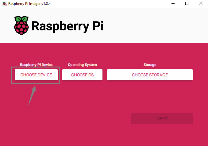
2. Select the corresponding Raspberry Pi. The device we used here was Raspberry Pi 4B, so we selected Raspberry Pi 4.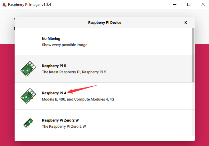
3. Then, click "CHOOSE OS" to select the operating system image to be burned.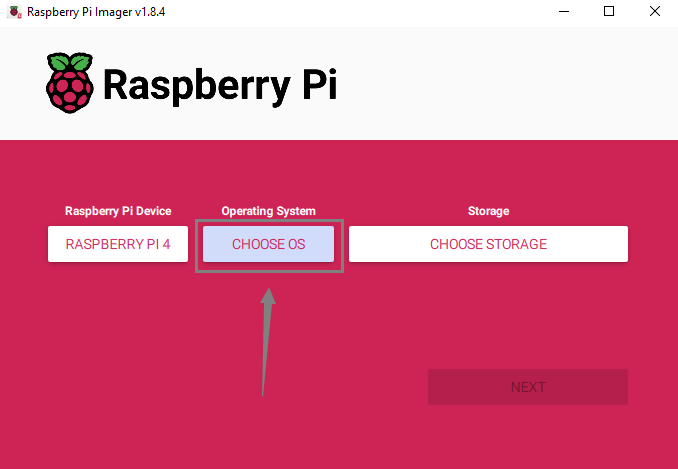
4. At the system selection interface, scroll to the bottom and click on "Use custom" to select the pre-configured image you downloaded earlier.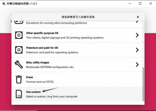
5. Then, click on "CHOOSE STORAGE" to select the SD card to be burned.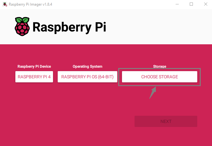
6. Once all the above options are selected, click "NEXT". A custom settings dialog box will pop up, select "EDIT SETTINGS" to configure the username and WiFi settings.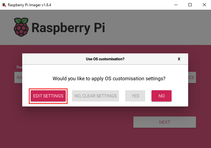
7. Set the username and WiFi in the "GENERAL" section as shown in the picture below. Both the username and password need to be set as "ws". Otherwise, it will cause the project program of the robot to not run properly after the Raspberry Pi boots up. The WiFi configuration needs to be changed to your own hotspot name and hotspot password, and the WiFi country selection should be based on your own country.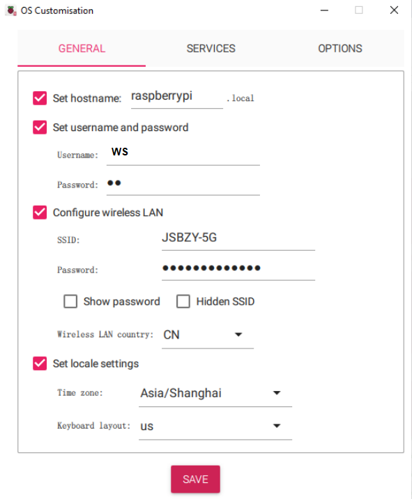
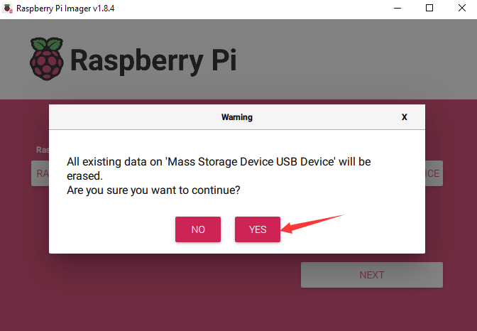
8. Next, enable SSH service in "SERVICES", then you can use SSH connection to control your Raspberry Pi system remotely. After setting up, click save, it will pop up that the data on the SD card will be deleted, select "Yes".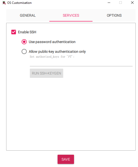
9. Start to burn the image, and wait for a while to finish burning, the Raspberry Pi Imager will automatically pop up the SD card, remove the SD card, and insert it into the Raspberry Pi. Turn on the main power switch and power on the Raspberry Pi. The Raspberry Pi will reboot a few times to load the image from the SD card, wait two to three minutes and it will boot up normally.
Resource
3D Drawing
STEP Model
Driver Board Schematic
Demo
FAQ
Question:When the chassis motor is disassembled only the front wheel motor lights up, is the rear wheel motor not working properly?
Yes, it is normal, the light on the rear wheel motor is not on because the interface on the rear wheel motor doesn't use the encoder on the motor.
Support
Monday-Friday (9:30-6:30) Saturday (9:30-5:30)
Mobile: +86 13434470212
Email: services01@spotpear.com