



- sales/support
Google Chat:---
- sales
+86-0755-88291180
- sales01
sales@spotpear.com
- sales02
dragon_manager@163.com
- support
tech-support@spotpear.com
- CEO-Complaints
zhoujie@spotpear.com
- Only Tech-Support
WhatsApp:13246739196
- Purchase/Shipping/Refund
WhatsApp:13424403025
- HOME
- >
- ARTICLES
- >
- Common Moudle
- >
- ESP
ESP32-MINI-Drone-A User Guide
I. Project Overview
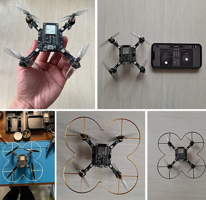
Based on an ESP32 development board, this mini quadcopter uses the ESP32 board as the main controller, employs only a single gyroscope sensor, and comes with a built-in web-based remote controller. Its minimalist hardware and software design makes it easy to get started with—only simple soldering and firmware flashing are required, and it can take off without complex configuration.
The aircraft comes with a built-in web-based remote controller, so you can control it simply by accessing it from your phone—no need to install an additional app or use a physical remote. Of course, it also supports app-based and physical remote control.
Simple yet sophisticated—every detail has been carefully refined.
Specifications
- Main controller: ESP32
- Wheelbase: approx. 118 mm
- Weight: approx. 80 g (including standard battery)
Quick Start
III. Project Replication
Just follow the steps and it will definitely fly! Replication takes only three steps:
- Hardware Assembly
- Software Flashing
- Simple Debugging
Step 1: Hardware Assembly
1. Download the [Bill of Materials spreadsheet] from the attachments on this page, prepare the materials according to the BOM, and fabricate the PCB.
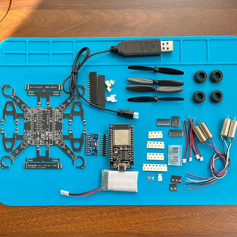
The PCB thickness should preferably be 1.6 mm, as the slot dimensions for the base and bracket are designed for 1.6 mm.
Try to buy higher-quality main components; accessory quality varies widely and will directly affect the build results.
The development board is an ESP32 30-pin. Those who are new to development boards should note that ESP32 boards come in many versions, such as C3/S3/CAM, etc. What you need is the version with no suffix—ESP32—with 30 pins.
The battery is a 1S RC model/drone battery with a voltage of 3.7–4.2 V. Do not buy an ordinary lithium battery; one with a high discharge rate is required.
The complete bill of materials is provided in the [BOM spreadsheet] in the attachment at the bottom of this page, including model numbers, packages, and detailed descriptions. The BOM only covers circuit components, and placing an order directly from it may result in mismatches; it is for reference only.
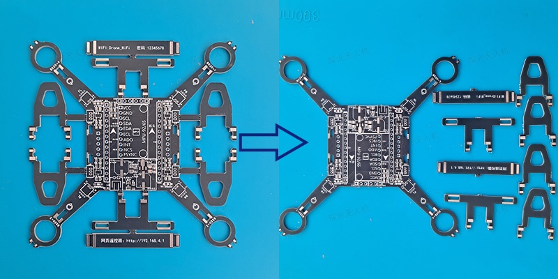
2、Separating the PCB. The front, back, left, and right sections are the motor mounts and bracket parts, while the middle section is the main control board. The new PCB has added silkscreen markings for the corresponding divisions.。
Before assembly, separate the main control board section from the motor mounts and hanger. You can use tools to help with the separation—flush cutters make it easy to cut them apart.。
3、Soldering the components. If you are soldering with an electric soldering iron, it is recommended to solder the smallest SMD components first, then the larger SMD components, and finally the through-hole components, pin headers, sockets, etc.
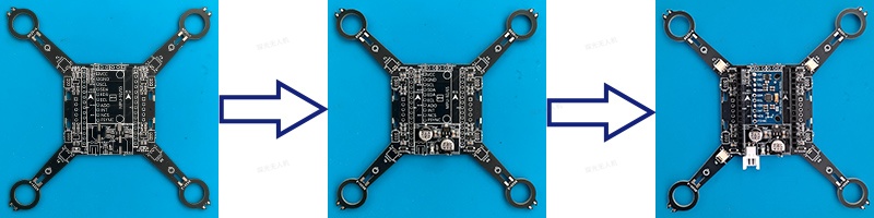
There are two relatively large 470 µF capacitors on the main control board to relieve pressure on the battery. If you buy a battery of good quality, these two capacitors can be omitted. The LED is also a non-essential component and can be left uninstalled.
The gyroscope module can be soldered flush against the main control board without pin headers, which reduces installation deviation. If you are not skilled at soldering, it is recommended to use pin headers for soldering.
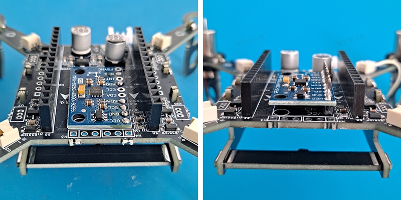
The gyroscope module can be soldered with only the VCC / GND / SCL / SDA / AD0 / NCS pins, or all pins can be soldered.
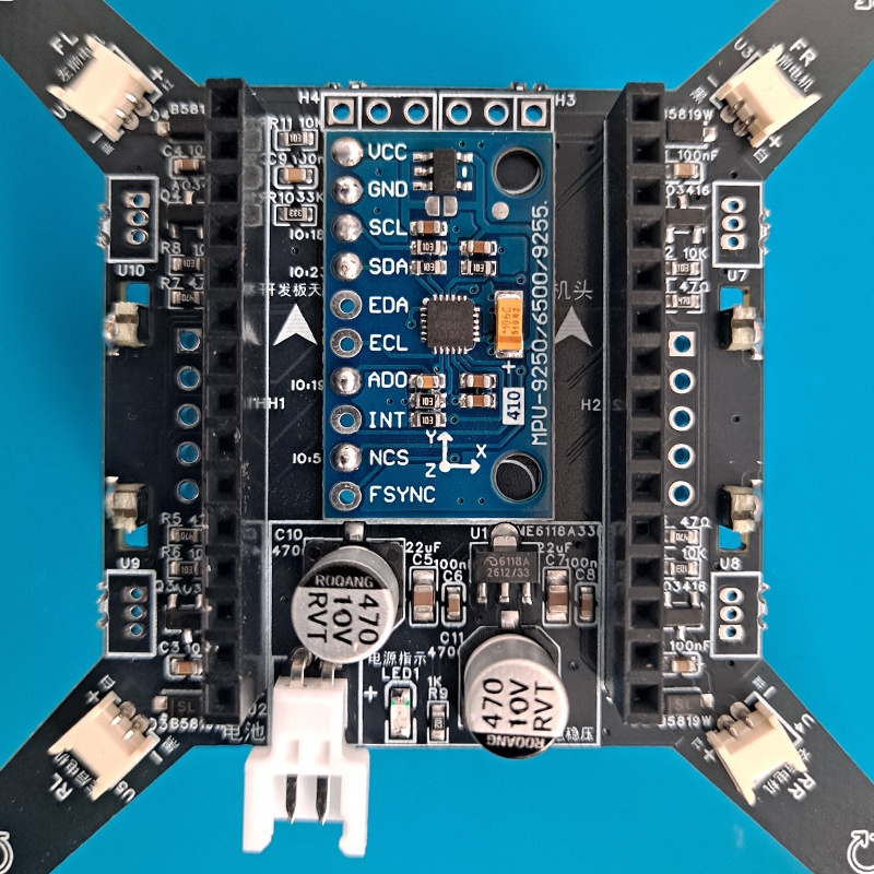
After soldering is complete, it is recommended to use a multimeter to do a simple test of the circuit for cold solder joints or short circuits, and confirm there are no problems before applying power. Even a welder with 30 years of experience using an electric soldering iron cannot guarantee success the first time when soldering 0603 components.
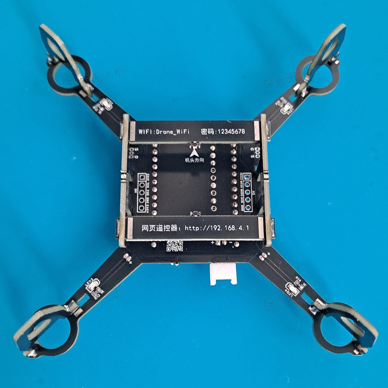
4、Soldering the motor mounts and brackets. The motor mounts can effectively protect the drone when it loses control, and they also serve as support for the entire aircraft. Installation is recommended.。
The bracket can be used to hold the battery. The bracket is 12 mm high, so batteries with a thickness of less than 12 mm will fit. You can also use a rubber band to secure the battery.。
There are soldering pads near the bracket; reinforce them with solder.。
Here's what it looks like after soldering.
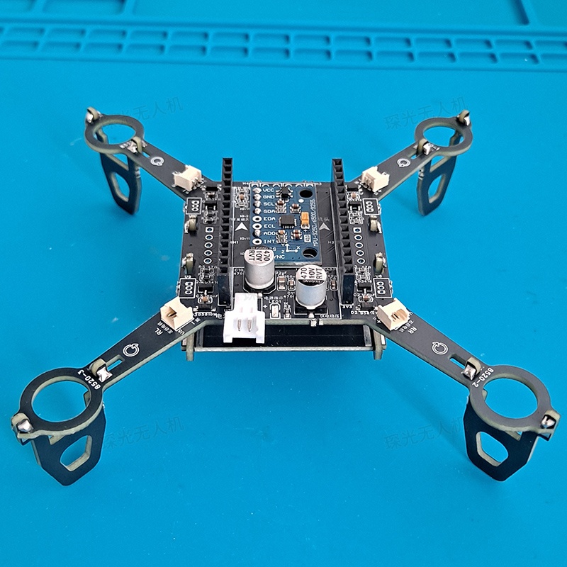
The back side.
5、Installing the motors. The motor rotation direction must follow the specified direction; the PCB has silkscreen markings indicating the corresponding rotation direction, and the two diagonal motors must rotate in the same direction.
It is recommended to use two motors with black-and-white wires and two with red-and-blue wires, as color-coded installation is more intuitive. The PCB silkscreen indicates the wire colors and polarity. Alternatively, four motors with the same wire color can be used.。
The motors are secured to the bracket with rubber rings, or fixed directly with hot glue.
Reference for motor rotation direction.:
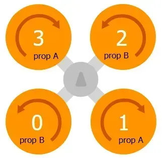
6、Installing the propellers. The propellers must also be installed in the specified direction!
When the motor rotates in the marked direction, the higher side of the propeller should face forward and blow air downward. The diagonal propellers must also face the same direction. You can refer to the installation direction shown in the figure below.
The most reliable approach is, after debugging is complete, to arm the motors and confirm that all four propellers blow air downward.
The mechanical strength of the motors and propellers is limited, so do not use excessive force during installation—just install them snugly.
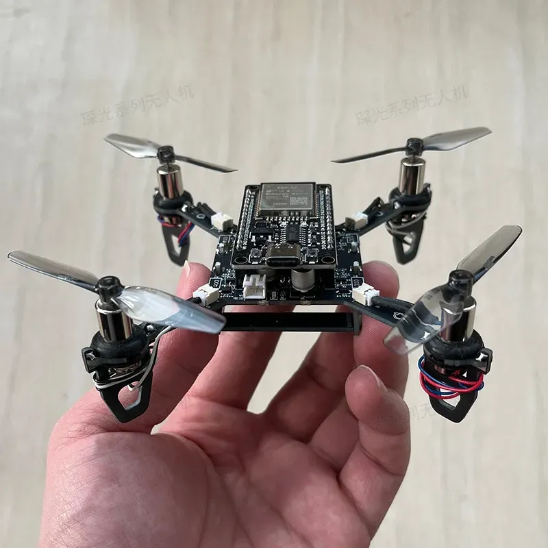
The propeller guards are 3D-printed parts. The model files are in the attachments and can be downloaded and printed. Installing them makes it safer, so installation is recommended.
Step 2: Software Flashing
1. Download the compiled BIN firmware file.。
MINI firmware 20261021.bin
2、Connect the ESP32 development board to the computer using a USB data cable. (If the computer does not automatically install the serial port driver, you need to install it manually; you can check this in the computer's Device Manager.)
3、Use the official Espressif tool to flash the firmware. Download address for the flashing tool.:https://docs.espressif.com/projects/esp-test-tools/zh_CN/latest/esp32/production_stage/tools/flash_download_tool.html
Flashing settings:
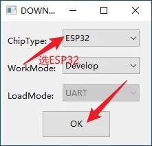
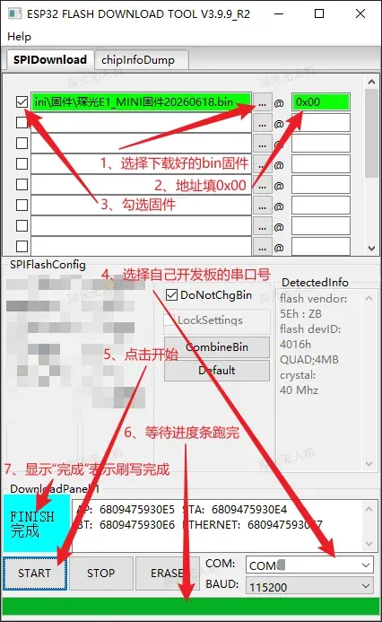
If you don't know which serial port to use, plug and unplug the development board and see which port number changes—select that one.
Step 3: Debugging and Takeoff
1、Connect the battery to the drone, and connect your phone to the drone's Wi-Fi: Drone_WIFI, password: 12345678.
Some phones have an automatic network optimization feature that automatically switches between Wi-Fi and mobile data, so it needs to be disabled; or a more direct approach: turn off mobile data on your phone.
2、Open your phone's browser and enter the address.:http://192.168.4.1 After confirming, open the remote controller interface.
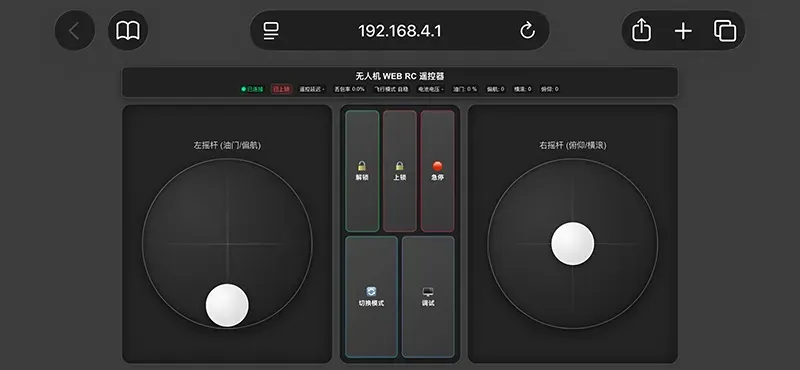
3、Debugging. In the web-based remote controller, click the "Debug" button, and you can enter debugging commands in the pop-up debug interface. It is recommended to remove the propellers before debugging.
- Calibrate the IMU (required). Enter the debug command "ca" and position the drone according to the prompts. Refer to this prompt:
1/6 Place horizontally: nose facing forward (normal flight direction), bottom facing down, placed horizontally on a flat surface, ensuring it is completely level with no tilt. Keep it still; calibration will begin after 8 seconds.
Horizontal calibration complete. Please continue.
2/6 Nose up: Keep the nose facing forward, point the nose toward the sky, and let the tail face down and touch the supporting surface, perpendicular to the ground. Keep it still; calibration will begin after 8 seconds.
Nose-up calibration complete. Please continue.
3/6 Nose down: Keep the nose facing forward, point the nose toward the ground and touch the supporting surface, with the tail facing up and perpendicular to the ground. Keep it still; calibration will begin after 8 seconds.
Nose-down calibration complete. Please continue.
4/6 Right side down: Keep the nose facing forward, position the right side of the aircraft downward and touching the supporting surface, with the left arm facing up and perpendicular to the ground. Keep it still; calibration will begin after 8 seconds.
Right-side-down calibration complete. Please continue.
5/6 Left side down: Keep the nose facing forward, position the left side of the aircraft downward and touching the supporting surface, with the right arm facing up and perpendicular to the ground. Keep it still; calibration will begin after 8 seconds.
Left-side-down calibration complete. Please continue.
6/6 Upside down: Keep the nose facing forward, completely flip the aircraft so the top faces down and the bottom faces up, with the whole unit in a horizontal upside-down position. Keep it still; calibration will begin after 8 seconds.
✓ All calibration complete! Return the aircraft to an upright position and run the ps command to view the calibration results.
After calibration is complete, return the drone to an upright position (top facing up) and enter the command "ps" to view the calibration results. You will see something like:
roll: 0.521120 pitch: -0.062948 yaw: 82.711197
If roll/pitch are close to 0, calibration is successful. The normal range is within 0.5, the acceptable range is within 2, and if it exceeds 5, recalibration is required.
yaw can be ignored; the MPU6500 has no magnetometer, so the yaw axis is a virtually calculated value.
IMU calibration only needs to be done once. After that, as long as there is no major deviation, hardware replacement, or firmware rewrite, it does not need to be done again.
- Test the motors (optional). First remove the propellers from the motors! To avoid injury!
Enter the commands "mfl/mfr/mrl/mrr" respectively, corresponding to the front-left, front-right, rear-left, and rear-right motors, and observe whether the four motors rotate normally.
If your phone screen is too small and debugging is inconvenient, you can also use Arduino or GQC for debugging. Refer to the content in the "In-Depth Study" section.
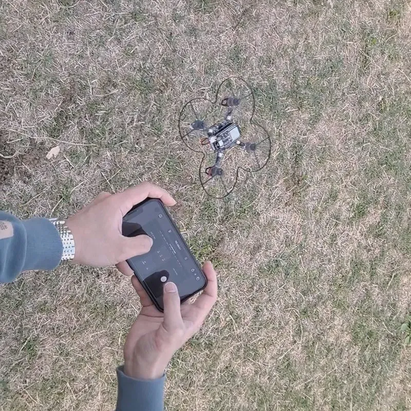
4. Takeoff. Click the arm button, push the throttle, and take off!
IV. In-Depth Study
If you are only doing a simple replication, the following sections can be ignored.
This project is released under the CC BY-NC-SA open-source license; commercial use without authorization is prohibited.
Related Resources
Hardware and software documentation, FAQs:http://docs.cherglowtech.com/
Companion ground station (under development):https://gc.cherglowtech.com/
Open-source flight controller source code:https://github.com/songge8/CF-Drone
The flight control software is developed using Arduino and can be developed and compiled with Arduino. The console built into the Arduino IDE can also be used for aircraft debugging. The aircraft can also use flight control programs written in any development language, as long as they are compatible with the ESP32 and MPU6500 hardware.
Design drawings and schematics.:https://pro.lceda.cn/editor#id=05f7ecdc689445648d7267c7c936f432
Reserved interfaces.
The main board has four reserved data interfaces, by default I2C, SPI, remote control receiver, and spare. They can be used to connect external devices such as sensors and remote controls, or to supply power to external devices.
The Chenguang sensor expansion module is perfectly compatible with the reserved interfaces. It includes a barometer, magnetometer, laser rangefinder, and optical flow sensor, enabling altitude hold or position hold hovering. The flight controller automatically detects whether the corresponding sensors are present and automatically enables altitude hold and position hold flight modes.
A brushless ESC interface is reserved, allowing brushless motors to be installed without modifying the original hardware.
支持实体遥控、手机APP遥控和MAVLINK协议
实体遥控
主板预留的遥控接收机接口,支持主流的CRSF(ELRS)/SBUS遥控协议。SBUS已实现软件反向,无需硬件反向器;CRSF(ELRS)支持单向控制输入,只需接 接收机GND、5V、TX → 无人机G、V、IO4。
实体遥控设置方法:
- 确保遥控和接收机连接正常,接收机协议设置正确;
- 连接无人机和接收机;
- 通过控制台命令设置接收机接口机协议和相应的波特率:RC_PROTOCOL,遥控协议,0=SBUS,1=CRSF(ELRS)(默认);RC_BAUD,遥控串口波特率(bps),SBUS=100000,CRSF=420000(默认);命令格式示例:P RC_PROTOCOL 1;
- 校准遥控,控制台使用CR命令按提示操作;
- 左摇杆右下打满为解锁,左下为上锁
QGC手机APP
APP可在QGC官网https://qgroundcontrol.com/ 下载。 除了可以用于控制飞机,APP-Analyze Tools-Mavlink控制台也可以用于飞控调试。
MAVLINK
固件支持MAVLINK协议。
无线模式
网页遥控/APP遥控支持AP模式(默认)和STA模式。
图传
可以参考评论区或视频教程评论中网友的实现方案。
五、更新日志
V1.3
- 预留数据接口扩展为4组,默认为I2C、SPI、ELRS/CRSF/SBUS、备用;
- 重新计算尺寸、位置数据,更高的机械精度;
- 重新布线,保留完整地平面且进行分区
常见问题
几处有极性的器件连接技巧
不同硬件版本元件位置和方向可能不同,以实际PCB丝印为准。
- 二极管,元件竖线为负极,对应PCB丝印竖线。
- LED,元件正面绿色脚/背面箭头方向为负极,对应PCB丝印尖头。
- 电解电容,元件黑色标记为负极,元件底面形状对应PCB丝印形状即可。
- 电机线接头,电机线和插头线有一根颜色一致即可,红对红,黑对黑。(此条非行业标准,仅针对物料包器件)
元件焊接位置
通过以下任一方式都可以
- PCB上印有每个元件的位号、数值。通过位号或者数值找到对应位置。(推荐)
- 在线互动式元件位置对照图 https://pcbbom.cherglowtech.com/pcb/E1MiniV1.3Y
- PCB设计图
烧录固件时无法下载/卡在同步
烧录过程大约几十秒钟,如果报错、过短、过长时间没有完成,按照以下项目逐项排查:
数据线直接插电脑USB口,不要使用USB HUB或拓展坞。
数据线建议使用安卓手机数据线。有些只有充电功能的数据线无数据传输功能。
检查串口驱动是否安装成功,驱动安装好后,在 电脑设备管理器-端口 项目下,应该能看到类似"USB-SERIAL CH340(COMX)"。
如果看不到端口,安装CH340或对应串口芯片驱动后再试。
CH340驱动官方下载地址https://www.wch.cn/downloads/CH341SER_MAC_ZIP.html不要同时打开arduino和乐鑫刷写工具,串口会被占用。
确认刷写工具开发板型号选择正确,核对刷写工具标题栏显示的开发板型号是ESP32。
可能开发板没有进入下载模式。按如下操作:
开发板插入USB,打开ESP32烧录软件,选择开发板串口,按住开发板BOOT键不松,点击烧录软件START,看到开始连接后松开BOOT键,开发板进入下载模式。确认是从官方渠道(工程文档、QQ群文件等)下载的对应型号的固件。其它三方固件,MINI/Nano固件不通用。
烧录地址“0x00”,其中“0”为阿拉伯数字,“x”为英文,不能用其它字符代替。
确认选择了正确的开发板串口号。开发板串口号必须选择,不能手动输入。
无人机WIFI找不到/连不上
通常无人机WIFI信号会在通电后几十秒内出现,手机刷新信号会有一定延迟,如果长时间没有出现请按下面步骤排查。
开发板不插无人机,单独连接USB数据线,避免线路短路造成开发板无法正常启动,影响问题判断。
确认是从官方渠道(工程文档、QQ群文件等)下载的对应型号的固件。其它三方固件可能没有WIFI功能,MINI/Nano固件不通用。
确认固件已正确写入,建议使用最新固件,有时电脑接口/数据线接触不良造成写入错误会导致WIFI无法连接、密码错误,可以更换电脑接口/数据线,清除开发板存储后重新刷写固件再试。
正确的默认WIFI名称:Drone_WiFi,密码:12345678(机身上有)。
如果修改过账号密码请使用修改后的账号密码连接,忘记密码可以清除开发板存储后重刷固件重置。
ESP_XXXXXX 开头WIFI信号为开发板出厂默认信号,说明没有成功刷写固件,刷写固件后再试。电池电量过低可能无法驱动WIFI。
正确写入固件后,开发板重新上电,开发板蓝色指示灯会闪一下。如果蓝色指示灯不亮或常亮,说明固件没有成功写入或程序没有成功运行,按下面的方法排查。
关闭刷写工具/Arduino,防止端口占用,打开网页控制台https://tools.cherglowtech.com/espwebconsole/ ,连接开发板串口,查看是否有报错信息。
E (30) qio_mode: Failed to set QIE bit, not enabling QIO mode
assert failed: __esp_system_init_fn_init_flash startup_funcs.c:118 (flash_ret == ESP_OK)
Backtrace: 0x4008c03c:0x3ffe3a70 0x4008c001:0x3ffe3a90 0x40092905:0x3ffe3ab0 0x400fa6df:0x3ffe3bf0 0x400fbc26:0x3ffe3c10 0x400fbc5e:0x3ffe3c30 0x40081dd6:0x3ffe3c60 0x40079912:0x3ffe3c90 |<-CORRUPTED
ELF file SHA256: 242e6edee
E (408) esp_core_dump_flash: Core dump flash config is corrupted! CRC=0x7bd5c66f instead of 0x0
E (416) esp_core_dump_elf: Elf write init failed!
E (421) esp_core_dump_common: Core dump write failed with error=-1
Rebooting...
如果控制台循环显示以上信息,请截图联系客服,开发板需要返厂检查。
网页遥控打不开
连接前先确认无人机固件已刷写好。
确认是从官方渠道(工程文档、QQ群文件等)下载的固件。
确认手机已连接上无人机WIFI,手机流量已关闭。
网页遥控地址 http://192.168.4.1
或 http://192.168.4.1:8080 (仅旧版本固件使用,已废弃)网页遥控地址中的符号全部为英文符号,不要使用中文符号。
有些浏览器要区分地址栏和搜索栏,地址必须输到地址栏。
不要使用微信/QQ内置浏览器,这些浏览器一般会有特殊限制。
提示IMU故障
项目中常提到的IMU、陀螺仪模块、姿态传感器、加速度计实际都是指IMU(MPU6500模块)。
这个提示说明IMU(MPU6500模块)虚焊、短路、工作不正常。
旧版固件(202609xx前的版本)不支持扩展模块,如果旧版本固件安装了扩展模块,会直接报错IMU故障。使用拓展模块建议使用最新版本固件。
解锁提示未校准加速度计
网页遥控调试或控制台使用"ca"命令,按照提示校准IMU后再操作即可。
IMU校准数据正常范围
使用ps命令查看校准后的姿态数据,roll/pitch接近于0即校准成功,正常范围0.5以内,合格范围2以内,超过5需要重新校准。yaw可忽略,mpu6500没有磁力计,yaw轴为虚拟计算数值。
IMU校准后ROLL项显示170+
将机身放正(开发板朝上,飞机底部朝下),再执行PS命令。
如果机身放正后执行PS命令仍然显示170+,说明校准不正确,需要重新执行校准操作。
IMU校准后数据都是NAN 或 PS命令显示姿态数据roll/pitch全是0.000
IMU(MPU6500模块)虚焊、短路、工作不正常。(新版固件会提示IMU故障)
IMU校准时长时间卡在第一步,甚至遥控断连
IMU(MPU6500模块)虚焊、短路、工作不正常。(新版固件会提示IMU故障)
IMU每次开机都需要校准吗?
IMU校准只需要完成一次,以后如果没有大的偏差、硬件更换、固件重写就不需要再做。
上电后不做任何操作电机会转吗?
开发板没有刷写固件前部分引脚可能会有默认上拉,可能会启动电机。没有刷写固件前不要上电,或去掉开发板再上电。
正常情况上电后不做任何操作电机不会转,解锁后才会转。
如果上电后不做任何操作电机会转,检查这路电机的驱动电路,这种情况可能是:
- 10K电阻虚焊;
- MOS管烧坏导通。
解锁后(怠速时)电机有的转,有的不转
需要测试排查电机、电路问题,按下面的步骤进行:
使用网页遥控/控制台调试命令mfl/mfr/mrl/mrr依次测试(测试前去除桨叶!)。如果电机转动正常则说明电机、驱动电路硬件均正常;不转说明这一路电机或驱动电路不正常,需要继续排查。
单独测试电机好坏,把电机取下,电机正负极直连可调电源,1V电压下电机能转说明电机正常。如果没有可调电源可用1.5V干电池或无人机电池代替。
如果调试命令测试电机不转,单独测试电机正常,则判断电机驱动电路可能存在问题。检查电机驱动电路47Ω、10KΩ电阻、MOS管是否虚焊、短路、损坏。(这种情况最常见)
加油门电机转速不一致
加油门时,电机转速通过飞控姿态计算等算法实时调整,不是由电池直接供电,转速不同是正常的。但如果是侧翻或无法起飞,请按侧翻问题排查。
如果需要测试电机,使用网页遥控/控制台调试命令mfl/mfr/mrl/mrr。
加油门起飞时无人机侧翻或部分电机停转
正常起飞的必要条件:
- 电池实际放电倍率在25C及以上(官方套件电池已实测符合要求)
- 电池电量充足。
- 电机旋转方向必须正确。
- 桨叶方向安装必须正确。
- IMU校准无误,校准误差在合格范围内。
- 电路没有虚焊、短路。
排查以上问题后,应该都可以正常起飞。
网页遥控怎么操作
网页遥控布局为美国手。可以在网上找一些穿越机操控教程学习。
左摇杆上下为油门,左右为偏航;右摇杆为上下为俯仰,左右为横滚。
这是无人机的专业叫法,新手可能误解,所以新版固件中改成大白话了:
左摇杆,上:油门加;下:油门减;左:左转;右:右转;
右摇杆,上:前进;下:后退;左:左移;右:右移。
飞行模式说明
特技(穿越机模式):手动油门,松油门自动回零;手动控制姿态,姿态不自动回正。
自稳(穿越机模式):手动油门,松油门自动回零;手动控制姿态,姿态自动回正。
定高(类似某疆飞行模式,需配合传感器模块,安装后自动识别):自动油门,油门控制高度上下,松油门自动保持高度;手动控制水平方向;
定点(类似某疆飞行模式,需配合传感器模块,安装后自动识别):自动油门,油门控制高度上下,松油门固定高度悬停;自动保持水平方向,可手动调整,松手固定位置悬停。
无人机起飞后漂移
B站视频【琛光E1四轴飞行器漂移的分析和处理】
https://www.bilibili.com/video/BV1Jisd6pE64/
飞行距离/高度
理论可达几百米,但因为没有图传,只能在视距内飞行,实际几十米外就已经看不清飞机在哪了。
为什么收到的电池没电?
电池的最佳存放状态是半电,而且电池会自放电,所以收到不是满电的。充满电再使用即可。
套件中带有充电线,推荐使用5V1A充电头,标准电池约1小时左右充满,充电时充电线亮红灯,充满灯灭。
指示灯闪/不亮
电池接口旁LED、开发板红色指示灯为电源指示灯,上电后应该常亮。不亮或闪烁为供电有问题,检查供电电路。
开发板蓝色指示灯默认为状态指示灯。上电闪一下:程序自检。慢闪:解锁正常。快闪:报警(电量低、遥控失联等)。
飞机背面指示灯为电机运行指示灯,亮灭和电机通电状态一致:电机通电指示灯亮,电机断电指示灯灭,解锁前不亮,解锁后亮。
飞机背面电机指示灯亮度不一致/闪烁:电机指示灯亮度随电机转速变化,解锁后电机转速受算法控制实时变化,是正常现象。
MOS管烧坏
可能烧坏MOS管的情况:
- 电机接线短路;
- 电机堵转;
- 二极管接反、虚焊;
找不到BIN固件
固件在工程文档中、QQ群文件都可以下载到。
PS:源码为固件编译前的源代码,无法直接烧录使用,源码中没有固件。
PS:固件为琛光科技开发,均在琛光相关渠道提供;不要到乐鑫的刷写工具目录里或者刷写工具页面去找。
哪里的固件是最新的?
一般QQ群文件里的固件会更新一些,且最新测试版固件一般会发在QQ群;
立创硬件开源平台的固件一般为稳定版,且更新频率会稍微慢一些。
最新固件一般会领先稳定版固件数十个小版本,很多问题已在新版固件优化,但也可能会有未知问题,可以根据自身情况使用稳定版或新版固件。
U7U8U9U10/H3H4/H5H6是空的吗?
这些是预留接口,是空的。
U7U8U9U10为预留电调接口,如需改装无刷电机可用此接口连接电调;
H3为预留遥控器接收机接口,H4为备用预留接口;
H5H6为数据传输预留接口,默认适配琛光扩展模块。
下载
固件
保护圈3D模型
第三方工具、驱动
ESP32刷写工具
ESP32串口驱动
CH340驱动:
https://www.wch.cn/downloads/CH341SER_MAC_ZIP.html
技术支持
周一-周五(9:30-6:30)周六(9:30-5:30)
手机:13434470212
邮箱:services04@spotpear.cn
QQ:202004841

[Tutorial Navigation]
- I. Project Overview
- Specifications
- Quick Start
- 常见问题
- 几处有极性的器件连接技巧
- 元件焊接位置
- 烧录固件时无法下载/卡在同步
- 无人机WIFI找不到/连不上
- 网页遥控打不开
- 提示IMU故障
- 解锁提示未校准加速度计
- IMU校准数据正常范围
- IMU校准后ROLL项显示170+
- IMU校准后数据都是NAN 或 PS命令显示姿态数据roll/pitch全是0.000
- IMU校准时长时间卡在第一步,甚至遥控断连
- IMU每次开机都需要校准吗?
- 上电后不做任何操作电机会转吗?
- 解锁后(怠速时)电机有的转,有的不转
- 加油门电机转速不一致
- 加油门起飞时无人机侧翻或部分电机停转
- 网页遥控怎么操作
- 飞行模式说明
- 无人机起飞后漂移
- 飞行距离/高度
- 为什么收到的电池没电?
- 指示灯闪/不亮
- MOS管烧坏
- 找不到BIN固件
- 哪里的固件是最新的?
- U7U8U9U10/H3H4/H5H6是空的吗?
- 下载
- 技术支持