- sales/support
Google Chat:---
- sales
+86-0755-88291180
- sales01
sales@spotpear.com
- sales02
dragon_manager@163.com
- support
tech-support@spotpear.com
- CEO-Complaints
zhoujie@spotpear.com
- Only Tech-Support
WhatsApp:13246739196
- Purchase/Shipping/Refund
WhatsApp:13424403025
- HOME
- >
- ARTICLES
- >
- Common Moudle
- >
- Sensors
Finger-Vein-Scanner-Module-B User Guide
Overview
Introduction
This is a finger vein recognition module based on a 32-bit ARM Cortex-M4F processor, with a clock speed of up to 192MHz, supporting floating-point operations and DSP instruction sets, and can efficiently run biometric algorithms. The module adopts a lamp and board separation structural design, facilitating embedding into various terminal devices and enhancing the overall integration level. The module interface is compatible with the industry-standard protocol of fingerprint recognition, has good platform adaptability and scalability, and supports rapid development and deployment. It is widely used in smart security devices such as smart door locks, push-pull or hidden handles, small smart lockers, and access control and attendance systems, helping to achieve high-precision and high-reliability identity authentication solutions.
Specifications
| SOC | 192MHZ 32-bit ARM Cortex-M4F microprocessor |
| User capacity | 100 ID |
| Recognition speed | < 1s |
| Matching method | 1:1 or 1:N |
| Vein template data | Single template ≤ 1K bytes |
| False Acceptance Rate (FAR) | < 0.0001% (at high security level) |
| False Rejection Rate (FRR) | 0.01% (at higher security level) |
| Communication interface | USB: Adaptive USB drive-free (Windows) |
| UART: 3.3V TTL, default baud rate: 57600bps | |
| Operating voltage | 3.3V (±3%) |
| Operating current | 19.5mA |
| Standby current | ≤ 5uA |
| Dimensions | 39.98 × 34.92 × 8.29 (mm) |
| Enclosure | ABS + PC |
| Fire rating | UL94-5VB |
| Waterproof rating | IP56 (except for the port, lamp and board parts) |
Onboard Interfaces
This module provides both TTL (UART) and USB pins. When users use it, they can choose different cables for connection according to their own usage.
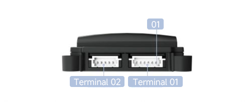
- Terminal 1: UART port (MX1.25 6PIN)
- Terminal 2: Lamp board communication port, provides lamp board power supply and USB interface communication (MX1.25 5PIN)
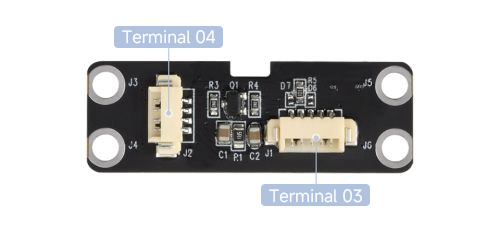
- Terminal 3: Lamp board communication port, obtains lamp board power supply and USB interface communication (MX1.25 5PIN)
- Terminal 4: USB communication port (MX1.25 4PIN)
| No. | Name | Function | Specification |
|---|---|---|---|
| 01 | TCH-3.3V | External normal 3.3V power input positive | Used in low power mode |
| 02 | WAKE-ON | Touch signal wake-up output | Active at high level |
| 03 | VCC-3.3V | External 3.3V power input positive | ±3% |
| 04 | TTL-RXD | Asynchronous TTL serial port receive | 3.3V level |
| 05 | TTL-TXD | Asynchronous TTL serial port transmit | 3.3V level |
| 06 | VCC-GND | External 3.3V main power input negative | Used in low power mode |
Hardware description
Connection Description
For two types of communication interfaces, we provide various cables to facilitate users in adjusting according to the products they are using.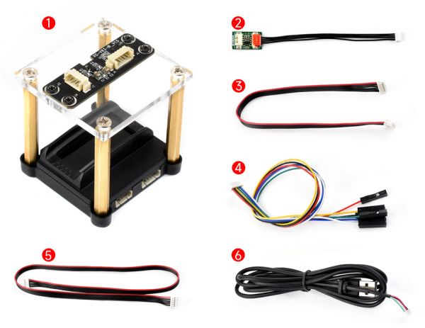
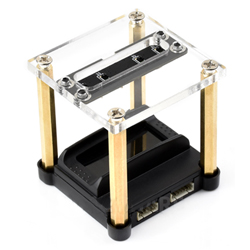
- Finger vein module + lamp and board
- 3.3V adapter board
- MX1.25 6PIN double-ended cable
- MX1.25 6PIN double-row cable
- MX1.25 5PIN double-headed cable
- USB cable
UART Connection
If you need to use the UART serial port to communicate, you can use the MX1.25 9PIN cable to connect the module to the motherboard, and connect the following pins through the corresponding pin definition table above, here take the Raspberry Pi motherboard as an example:
| Pin No. | Finger-Vein-Scanner | Motherboard (Raspberry Pi) |
|---|---|---|
| 03 | VCC-3.3V | 3.3V power pin |
| 04 | TTL-RXD | UART_TXD |
| 05 | TTL-TXD | UART_RXD |
| 06 | VCC-GND | GND |
Note: If the user customizes the motherboard interface, the provided MX1.25 6PIN dual header cable can also be directly connected.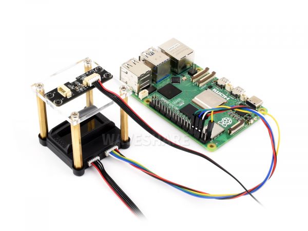
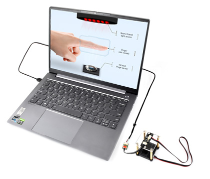
USB Connection
- If a user needs to use a USB interface for communication, they can connect using the provided 3.3V adapter board and USB cable. Here, the connection is made to the computer host.
- Connect the MX1.25 4PIN (9-to-4) cable to the module, connect the other side to the 3.3V adapter board, and then use the USB cable to connect it to the computer.
- Note: The power supply voltage of the module is 3.3V, if the user connect through other cables, please note that 3.3V power supply should be used, otherwise the device cannot be used normally.
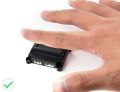
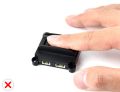
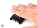
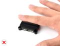
Finger Placement Description for Finger Vein Module
- Correct placements
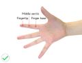
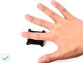
- Wrong placements

Software Description
Host Device Doftware
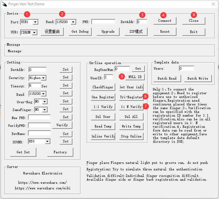
For the finger vein module, we provide a host device software for users to test and use conveniently. Users can download the test software from the Resources section, which supports the Windows system.
- Connect the device to the computer via USB according to the hardware connection instructions
- Open the test software
- Under normal circumstances, the device will automatically be recognized after being connected
- In the absence of interference from other devices, the port number defaults to USB1
- The device number defaults to 0
- The baud rate remains at the default 115200
- Click to connect device
- Click "Get empty ID" and the software will automatically fill in the available ID number
- Click "Vein registration" and place your fingers three times according to the voice and message prompts
- After the vein registration is successful, click "1:N Verification" to do a matching test on the fingers
- After testing, clicking "Close Device" can disconnect the communication with the device
Note: More software features to be updated
Description for Connecting Embedded Board
To be updated...
Resources
Support
Monday-Friday (9:30-6:30) Saturday (9:30-5:30)
Email: services01@spotpear.com