


- sales/support
Google Chat:---
- sales
+86-0755-88291180
- sales01
sales@spotpear.com
- sales02
dragon_manager@163.com
- support
tech-support@spotpear.com
- CEO-Complaints
zhoujie@spotpear.com
- Only Tech-Support
WhatsApp:13246739196
- Purchase/Shipping/Refund
WhatsApp:13424403025
- HOME
- >
- ARTICLES
- >
- Common Moudle
- >
- ESP
ESP32-S3-Relay-6CH Users Guide
Overview
Introduction
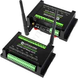
ESP32-S3-Relay-6CH is an industrial-grade 6-channel WiFi network relay based on ESP32-S3 main controller and supports WiFi, Bluetooth, RS485, Pico and other peripheral interfaces. It has built-in protection circuits such as power supply isolation and optodecoupler isolation, which is safe, stable and reliable, and suitable for the AIoT field.
Features
- Based on ESP32-S3 microcontroller with Xtensa 32-bit LX7 dual-core processor with frequency up to 240MHz
- Integrated 2.4GHz WiFi and Bluetooth LE dual-mode wireless communication, with superior RF performance
- High quality relay, contact rating: ≤10A 250V AC or ≤10A 30V DC
- Onboard isolated RS485 interface, for connecting to various RS485 Modbus industrial modules or sensors
- Onboard Pico compatible interfaces can be adapted to some Raspberry Pi Pico HAT, for expanding more functions such as RTC / CAN / RS232 / LoRa / sensor, etc.
- Onboard USB Type-C port for power supply, firmware downloading and debugging, making development more convenient
- Onboard power supply screw terminal, supports 7~36V wide voltage input, suitable for industrial applications
- Onboard optocoupler isolation to prevent interference with control chip from external high-voltage circuit connected to the relay
- Onboard digital isolation to avoid external signal interference with the control chip
- Onboard integrated power isolation, providing stable isolation voltage, no extra power supply required for the isolated terminal
- Built-in buzzer, RGB colorful LED, power supply and RS485 TX/RX indicators for monitoring the operating status of the module
- Rail-mounted ABS protective enclosure, easy to install, safe to use
Specifications
| Item | Parameter |
| Supply Voltage | 7~36V (or 5V/1A Type-C port) |
| Relay Channels | 6 channels |
| Contact Form | 1NO 1NC |
| Wiring port | Type-C |
| Communication protocol | USB protocol |
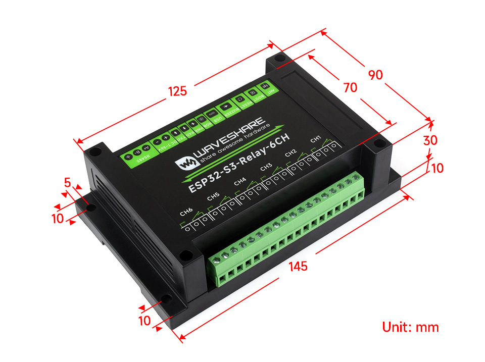
| Dimensions | 145 × 90 × 40 (mm) |
Onboard Resources
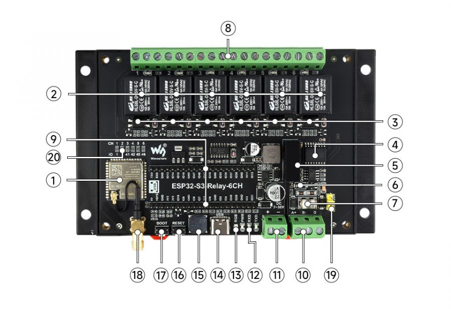
1. ESP32-S3 2. High-quality relay 3. Optocoupler isolation 4. Digital isolation 5. Power isolation 6. Onboard TVS (Transient voltage suppressor) 7. Ceramic gas discharge tube 8. Relay screw terminal 9. Compatible Raspberry Pi Pico interface 10. RS485 communication interface | 11. Power supply screw terminal 12. Operating status indicator 13. WS2812 RGB colorful LED 14. USB Type-C interface 15. Passive buzzer 16. RESET button 17. BOOT button 18. External antenna socket 19. RS485 matching resistor 20. Relay default control pin setting solder joint |
Interfaces
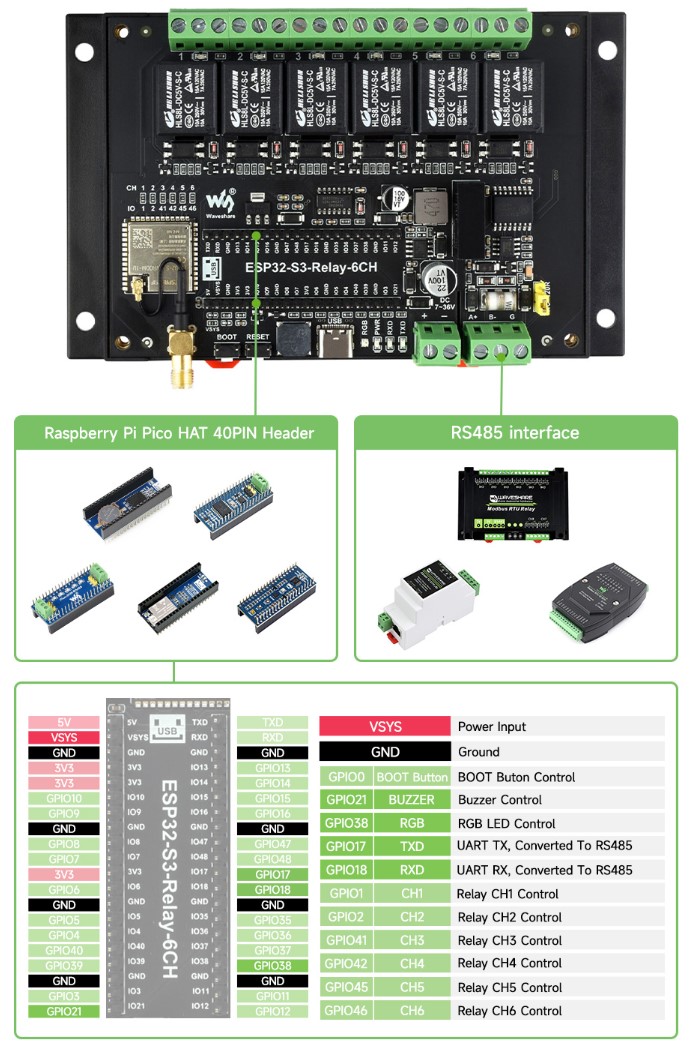
| Control GPIO | Function | Description |
| GP0 | BOOT button | BOOT button control pin |
| GP21 | BUZZER | Buzzer control pin |
| GP38 | RGB | RGB light control pin |
| GP1 | CH1 | Relay 1 control pin |
| GP2 | CH2 | Relay 2 control pin |
| GP41 | CH3 | Relay 3 control pin |
| GP42 | CH4 | Relay 4 control pin |
| GP45 | CH5 | Relay 5 control pin |
| GP46 | CH6 | Relay 6 control pin |
| GP17 | TXD | UART TX pin, corresponding to RS485 |
| GP18 | RXD | UART RX pin, corresponding to RS485 |
Dimensions
Electrical Safety Precautions
- This product should be operated and used by professional electricians or technical personnel. During use, please ensure electrical safety and take protective measures such as anti-leakage and insulation.
- Before installing, maintaining, or replacing relay equipment, make sure to turn off the power and unplug the device.
- Do not attempt to dismantle relay equipment to avoid damaging the device or risking electric shock.
- Please properly install and place the relay equipment. Avoid using it in damp, overly hot, or flammable environments to prevent safety accidents due to improper installation or use.
Usage Instructions
ESP32-S3-Relay-6CH currently provides two development tools and frameworks, Arduino IDE and MicroPython, providing flexible development options, you can choose the right development tool according to your project needs and personal habits.
Development Tools
| Arduino IDEArduino IDE is an open source electronic prototyping platform, convenient and flexible, easy to get started. After a simple learning, you can start to develop quickly. At the same time, Arduino has a large global user community, providing an abundance of open source code, project examples and tutorials, as well as rich library resources, encapsulating complex functions, allowing developers to quickly implement various functions. |
| MicroPythonMicropython is a full implementation of the Python 3 programming language that runs directly on embedded hardware such as ESP32, Raspberry Pi Pico, etc. You can run Python scripts directly on the board through REPL, which is very suitable for rapid prototyping. |

Each of these two development approaches has its own advantages, and developers can choose according to their needs and skill levels. Arduino and MicroPython are suitable for beginners and non-professionals because they are easy to learn and quick to get started.
Components Preparation
- ESP32-S3-Relay-6CH x 1
- USB cable (Type-A to Type-C) x 1
Working with Arduino
This chapter introduces setting up the Arduino environment, including the Arduino IDE, management of ESP32 boards, installation of related libraries, program compilation and downloading, as well as testing demos. It aims to help users master the development board and facilitate secondary development.
Environment Setup
Download and Install Arduino IDE
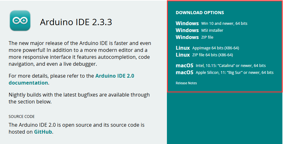
- Click to visit the Arduino official website, select the corresponding system and system bit to download
- Run the installer and install all by default
Install ESP32 Development Board
- Regarding ESP32-related motherboards used with the Arduino IDE, the esp32 by Espressif Systems library must be installed first.
- According to Board installation requirement, it is generally recommended to use Install Online. If online installation fails, use Install Offline
- For the installation tutorial, please refer to Arduino board manager tutorial
| Board name | Board installation requirement | Version number requirement |
|---|---|---|
| esp32 by Espressif Systems | "Install Offline" / "Install Online" | 2.0.12 |
Install library
- When installing Arduino libraries, there are usually two ways to choose from: Install online and Install offline. If the library installation requires offline installation, you must use the provided library file
For most libraries, users can easily search and install them through the online library manager of the Arduino software. However, some open-source libraries or custom libraries are not synchronized to the Arduino Library Manager, so they cannot be acquired through online searches. In this case, users can only manually install these libraries offline. - For library installation tutorial, please refer to Arduino library manager tutorial
- ESP32-S3-Relay-6CH library file is stored in the sample program, click here to jump: ESP32-S3-Relay-6CH Demo
| Library Name | Description | Version | Library Installation Requirement |
|---|---|---|---|
| ArduinoJson | Lightweight JSON library | v6.21.4 | "Install Online" or "Install Offline" |
| PubSubClient | MQTT message subscription publishing library | v2.8.0 | "Install Online" or "Install Offline" |
| NTPClient | Network time synchronization client library | v3.2.1 | "Install Online" or "Install Offline" |
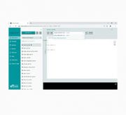
Run the First Arduino Demo
New Project
- Run the Arduino IDE and select
File->New Sketch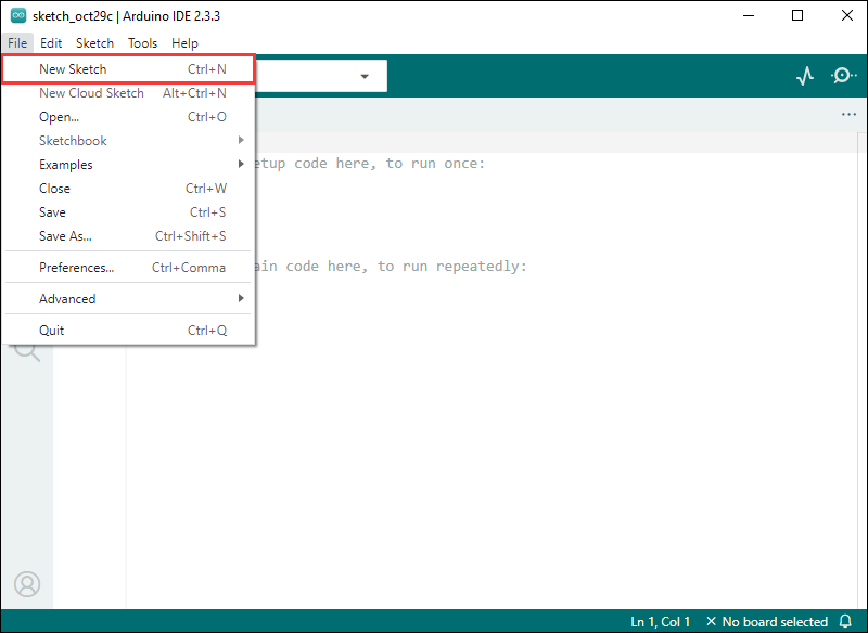
- Enter the code:
void setup() {
  // put your setup code here, to run once:
  Serial.begin(115200);
}

void loop() {
  // put your main code here, to run repeatedly:
  Serial.println("Hello, World!");
  delay(2000);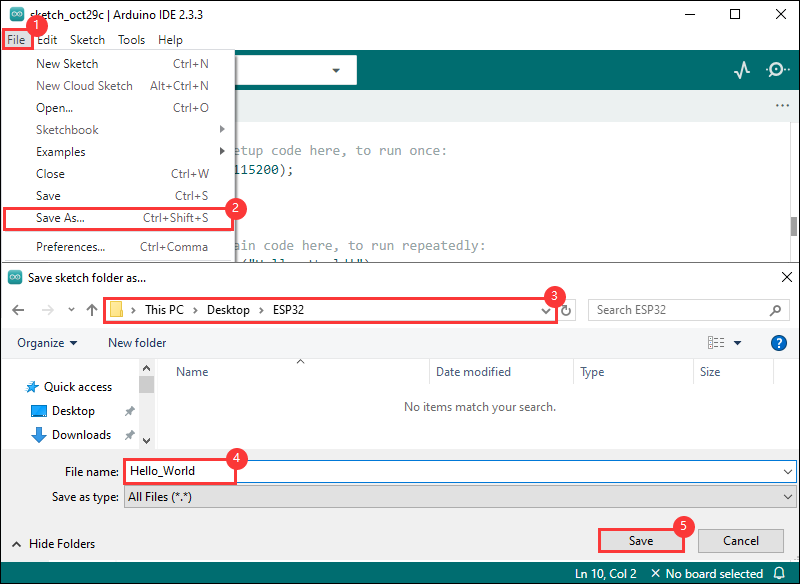
}- Save the project and select
File->Save As.... In the pop-up menu, select the path to save the project, and enter a project name, such as Hello_World, clickSave
Compile and Flash Demos
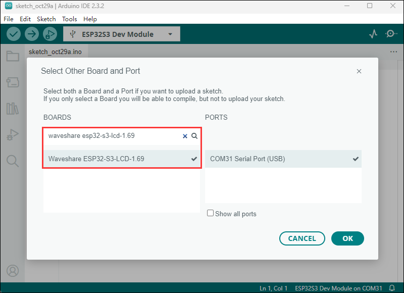
- Select the corresponding development board, take the ESP32S3 motherboard as an example:
①. Click to select the dropdown menu option Select Other Board and Port;
②. Search for the required development board model esp32s3 dev module and select;
③. Select COM Port;
④. Save the selection.
- Some development boards with specified version numbers support direct model selection, for example, "Waveshare ESP32-S3-LCD-1.69":
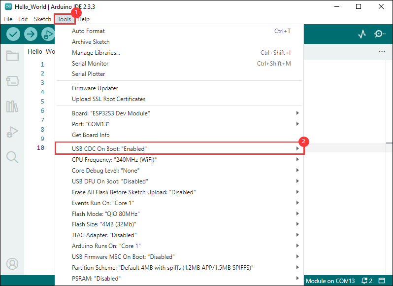
- If the ESP32S3 mainboard only has a USB port, you need to enable USB CDC, as shown in the following diagram:
- Compile and upload the program:
①. Compile the program; ②. Compile and download the program; ③. Download successful.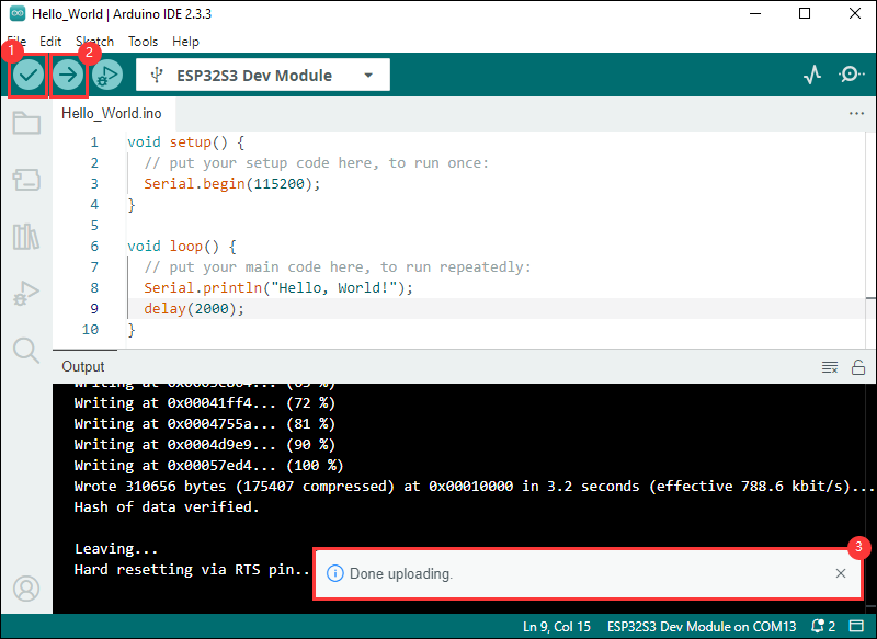
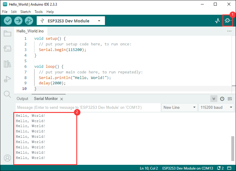
- Open the Serial Monitor window, and the demo will print "Hello World!" every 2 seconds, and the operation is as follows:
Demo

| Demo | Basic Description | Dependency Library |
|---|---|---|
| 01_MAIN_WIFI_AP | RS485 interface control, Bluetooth control, Bluetooth send IP, Web page control (short distance) | Can be flashed directly Web pages are only available if they are connected to device WIFI |
| 02_MAIN_WIFI_STA | RS485 interface control, Bluetooth control, Bluetooth send IP, Web page control (short distance) | Need to modify the WIFI to be connected Web pages can only be used within the intranet |
| 03_MAIN_WIFI_MQTT | RS485 interface control, Bluetooth control, Bluetooth transmit IP, Waveshare cloud control (long distance) | Need to modify the WIFI to be connected The device must be created in the Waveshare cloud |
| 04_MAIN_ALL | RS485 interface control, Bluetooth control, Bluetooth send IP, Web page control (short distance), Waveshare cloud control (long distance) | Need to modify the WIFI to be connected The device must be created in the Waveshare cloud Web pages can only be used within the intranet |
Arduino Project Parameter Setting

01_MAIN_WIFI_AP
Demo description
- This example implements the control of six relay switches through WiFi, Bluetooth, and RS485. The AP mode of WiFi is enabled in this example
Precautions
- Can be flashed directly
- Web pages are only available if they are connected to device WIFI
Code analysis
- Relay_Analysis(): This function is mainly used to analyze received data, perform corresponding relay control operations based on the data content, and output corresponding status prompt information.
- Parameter analysis
uint8_t *buf: A pointer to an unsigned 8-bit integer array, which is supposed to store the received data, and the function determines the content of the command based on the value of the first element (buf[0]) of the array.uint8_t Mode_Flag: The mode flag is used to represent the data source, and the corresponding data source prompt information (such as Bluetooth data, Wi-Fi data, or RS485 data) is output by judging this flag, and different relay operations are performed according to different commands.
- Logical flow
- First output the corresponding data source prompt message according to the value of
Mode_Flag. - Then use the
switchstatement to perform different operations based on the value ofbuf[0]:- For the cases from
CH1toCH6, thedigitalTogglefunction is used to switch the level states of the corresponding GPIO pins (such asGPIO_PIN_CH1, etc.), and the corresponding elements of theRelay_Flagarray are updated to record the change in relay status. TheBuzzer_PWMfunction is called to control the buzzer, and the corresponding on or off prompt information is output according to the final state of the relay. - For the
ALL_ONcommand, set all GPIO pins (corresponding to 6 channel relays) to high level (on state), use thememsetfunction to set all elements of theRelay_Flagarray to 1, indicating that all relays are turned on, output all relay ON prompt information, and control the buzzer. - For the
ALL_OFFcommand, set all relevant GPIO pins to low level (off state) similarly, update theRelay_Flagarray elements to 0, output a message that all relays are turned off and control the buzzer, and perform two additional buzzer control operations (with a delay in between). - If the value of
buf[0]does not belong to the above command cases, a prompt message for non-instruction data is output.
- For the cases from
- First output the corresponding data source prompt message according to the value of
- Parameter analysis
- WIFI_Init (): Configure the device as a Wi-Fi access point (AP), set up a Web server, and set up request processing functions corresponding to different paths to implement related network functions and device control functions, and give corresponding status prompts.
- AP creation
- First set the Wi-Fi mode to
WIFI_AP, and then attempt to create a soft AP throughWiFi.softAP(ssid, password). If it fails, it will loop through prompt and retry until it succeeds
- First set the Wi-Fi mode to
- Parameter configuration and prompts
- After successfully creating the AP, give a prompt with RGB light (green light on for 1 second)
- IP address display
- Obtain and format the IP address of the soft AP, store it in
ipStrand output it for easy network address recognition
- Obtain and format the IP address of the soft AP, store it in
- Web server setting
- Set up corresponding request handling functions (such as
handleRoot,handleGetData, etc.) for multiple paths (such as “/”, “/getData”, etc.) throughserver.on, each function should be defined elsewhere for different functional operations like returning pages, getting data, controlling switches etc. - Finally call
server.begin()to start the Web server and output a startup prompt message.
- Set up corresponding request handling functions (such as
- AP creation
02_MAIN_WIFI_STA
Demo description
- This example implements the control of six relay switches through WiFi, Bluetooth, and RS485. The STA mode of WiFi is enabled in this example
Precautions
- Need to modify the WIFI to be connected
- The Web page only supports controlling the device and this product to be used under the same network, if you use the mobile phone control, you need to turn off the mobile network
Code analysis
- WIFI_Init (): Connect the device to a specified Wi-Fi network in station (STA) mode. If the connection is successful, it will perform subsequent network-related configurations (such as obtaining an IP address, starting a Web server, and registering callback functions, etc.). If the connection fails, it will give a corresponding prompt and set the connection status flag. The process also provides visual connection status indicators through an RGB light
- Attempt to connect to Wi-Fi network:
- First set Wi-Fi to
WIFI_STAmode and enable sleep mode, then start connecting to the specified network. In the cyclic wait of unsuccessful connection, a point is output as a prompt every half second, and the RGB light briefly turns red on every even number of attempts (except the first attempt). If every 10 attempts fail, the connection is disconnected and reconnected. If the number of attempts exceeds 22, the connection is considered a failure and the loop is exited.
- First set Wi-Fi to
- Operations after successful connection:
- If the number of connection attempts is less than 23 (i.e. successful connection), set
WIFI_Connectionto 1, light up the green light for 1 second to indicate success, and then obtain and display the local IP address. Next, register callback functions corresponding to multiple paths for the web server (such as root path, data retrieval, control of different switches, etc.), and finally start the server and output startup prompt, so that the device can receive corresponding control through the web page.
- If the number of connection attempts is less than 23 (i.e. successful connection), set
- Operations after connection failure:
- If the number of attempts is greater than or equal to 23 (connection failure), set
WIFI_Connectionto 0, output a prompt to inform that the device can be controlled through Bluetooth debugging assistant, and light a red light to indicate a connection failure status
- If the number of attempts is greater than or equal to 23 (connection failure), set
- Attempt to connect to Wi-Fi network:
03_MAIN_WIFI_MQTT
Demo description
- This example controls 6 relays through MQTT, Bluetooth, and RS485 communication methods. It uses ESP32 as the main control unit, supports Wi-Fi and Bluetooth connections, and provides remote control based on the MQTT protocol
Precautions
- Need to modify the WIFI to be connected
- Must create the device in Waveshare Cloud
Code analysis
- Relay_Analysis(): Receive data from different communication sources and perform corresponding relay control operations
- Data Delivery: Commands (such as
CH1,ALL_ONetc.) are sent to the device via Bluetooth, Wi-Fi, or RS485. The device parses and executes the corresponding operation after receiving a command. For example, when the commandCH1is received, the function will switch the state of relay 1 - Data Feedback: The execution of control commands is printed to the serial monitor via
printf(e.g., relay status update: "Relay CH1 on") and fed back via the buzzerBuzzer_PWM). This allows users to see real-time status updates - Communication Protocol
- Bluetooth: Wireless communication with mobile phones or other devices through Bluetooth modules, and the device controls the relay after receiving the command
- MQTT: Connect to the MQTT server via Wi-Fi, and the device subscribes to a specific topic (such as relay control commands). When a new command is issued, the device receives the message via MQTT and performs relay control
- RS485: The device receives RS485 commands through the serial port and switches the relay status according to the commands
- Data Delivery: Commands (such as
- setup ()
- Initialize the various modules required for the system, including serial port, GPIO, RTC, Bluetooth and Wi-Fi (MQTT)
- Call
Bluetooth_Init(), and the device can establish connections with other Bluetooth devices and receive control commands - With
MQTT_Init(), the device will connect to the Wi-Fi network and be able to communicate with remote servers through the MQTT protocol
- Call
- Time Synchronization
- If the system is connected to Wi Fi and RTC is enabled, the
Acquisition_time()function will synchronize the current time to RTC through the network, ensuring that the device has accurate system time
- If the system is connected to Wi Fi and RTC is enabled, the
- Data Upload and Delivery
- Upload: When the device successfully connects to Wi Fi or Bluetooth, it can upload device status information or sensor data (such as temperature, humidity) through MQTT. These data will be sent to the MQTT server regularly for other systems or users to view
- Delivery: The device receives a control command from the MQTT server and performs corresponding actions, such as switching relays on and off or changing configurations
- Initialize the various modules required for the system, including serial port, GPIO, RTC, Bluetooth and Wi-Fi (MQTT)
04_MAIN_ALL
Demo description
- This example is a collection of RS485 interface control, Bluetooth control, Web page control (near distance), and Waveshare cloud control (long distance).
Precautions
- Need to modify the WIFI to be connected
- The Web page only supports controlling the device and this product to be used under the same network, if you use the mobile phone control, you need to turn off the mobile network
- Must create the device in Waveshare Cloud
External Expansion
RS485 Extended Relay Channels
- Use Modbus RTU Relay to extend 8-ch relay
- The 4 main example files are compatible with this operation, and the Extension_Enable in WS_imformification. h needs to be set to 1 (default is 1)
- Externally extended relays can be controlled via Bluetooth
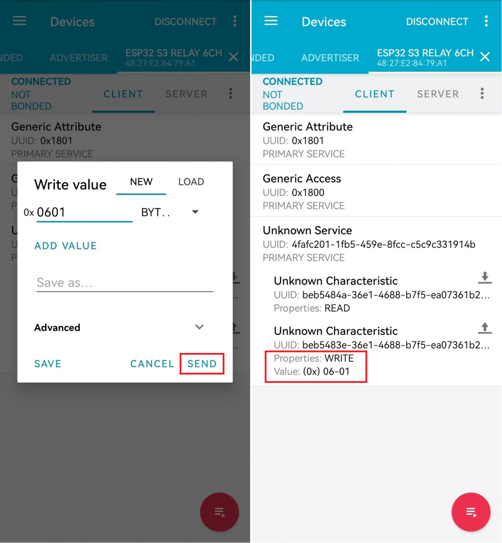
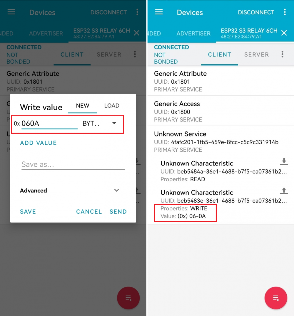
Operation Command Command Function 06 01 Switch the CH1 relay status of Modbus RTU Relay 06 02 Switch the CH2 relay status of Modbus RTU Relay 06 03 Switch the CH3 relay status of Modbus RTU Relay 06 04 Switch the CH4 relay status of Modbus RTU Relay 06 05 Switch the CH5 relay status of Modbus RTU Relay 06 06 Switch the CH6 relay status of Modbus RTU Relay 06 07 Switch the CH7 relay status of Modbus RTU Relay 06 08 Switch the CH8 relay status of Modbus RTU Relay 06 09 Turn on all relays of Modbus RTU Relay 06 0A Turn off all relays of Modbus RTU Relay
- The commands for Bluetooth control relay are characters 1-8, which are hexadecimal 0x06 0x01 ~ 0x38 0x0A
- Click the SEND button and fill in the data to be sent (currently hexadecimal sending), enter 0x06 0x01 as below
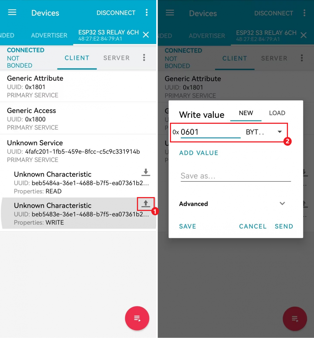
- Send 0x06 0x01 to control relay CH1 for status reversal
- Send 0x06 0x0A to control to turn off all relays
Extend Timer Switch Function with Pico Port
- Use Pico-RTC-DS3231 to extend timer switch function
- Please make sure that the RTC module time is accurate before connecting to the RTC module or connect the device to wifi to update the RTC module time before you can use the RTC timing function normally
- Connect the Pico-RTC-DS3231 device to ESP32-S3-Relay-6CH
- The 4 main example files are compatible with this operation, and the RTC_Enable in WS_imformation.h needs to be set to 1 (default is 0, please ensure that it is connected to Pico-RTC-DS3231)
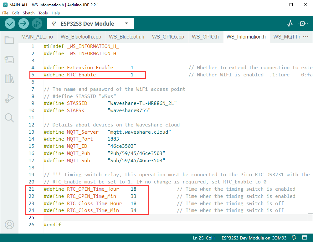
- Set the RTC_OPEN_Time_Hour, RTC_OPEN_Time_Min, RTC_Closs_Time_Hour and RTC_Closs_Time_Min to as the operation time
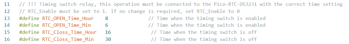
Parameter Parameter Description RTC_OPEN_Time_Hour The time to turn on all relays——hours RTC_OPEN_Time_Min The time to turn on all relays——minutes RTC_Closs_Time_Hour The time to turn off all relays——hours RTC_Closs_Time_Min The time to turn off all relays——minutes
- The following settings are set to open at 8:06 am and close at 4:30 pm every day
Extend CAN Port with Pico Port
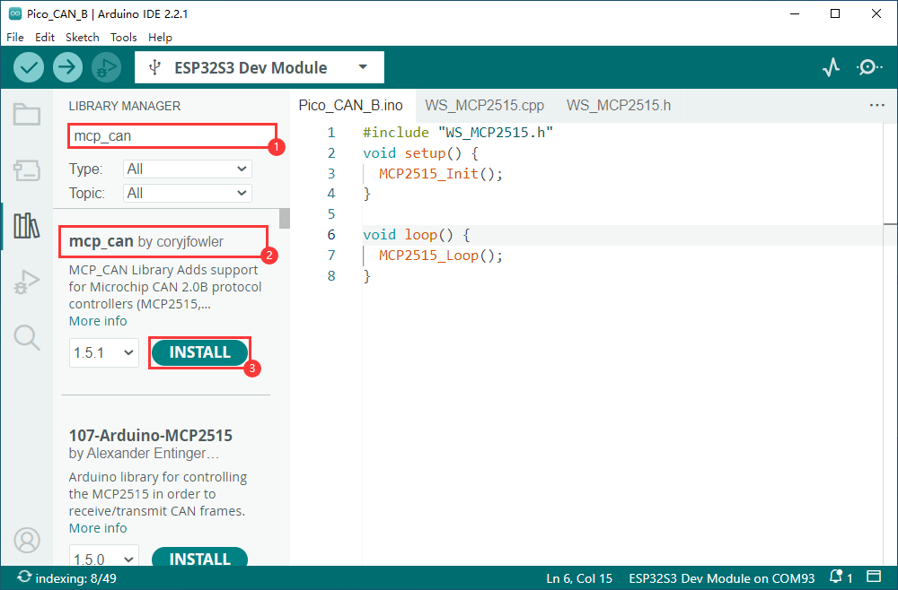
- Use Pico-CAN-B extend CAN communication port
Preparation
- Install mcp_can library
Tutorial
- Connect the Pico-CAN-B device to ESP32-S3-Relay-6CH
- Power on after connecting Pico-CAN-B to USB-CAN-A

- Download the provided Pico-CAN-B Demo
- Modify the demo according to the required operation

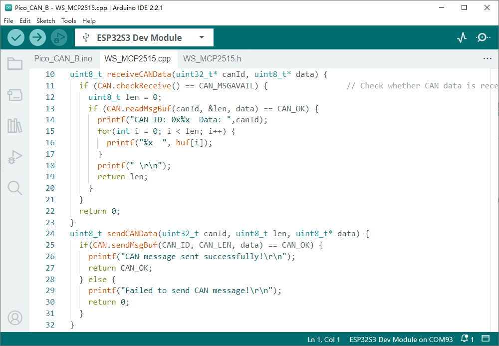
- In the main program, reference WS_MCP2515.c and WS_MCP2515.h
- After referencing, you can receive CAN data and send CAN data in the main program via the functions receiveCANData(uint32_t* canId, uint8_t* data) and sendCANData(uint32_t canId, uint8_t len, uint8_t* data)
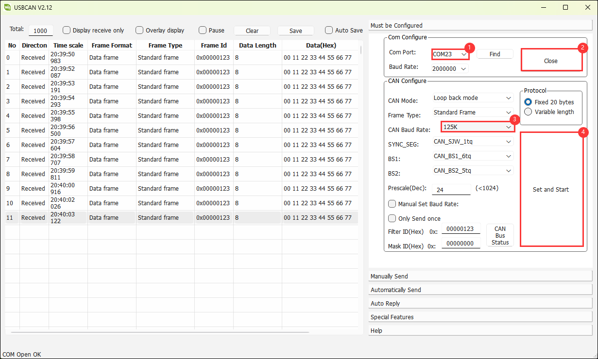
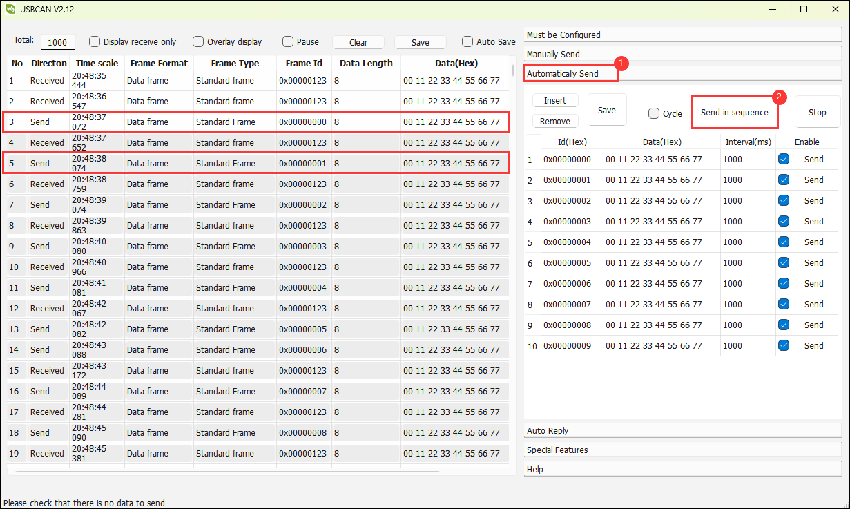
- Data reception: Use USB-CAN-A_TOOL for debugging
- Data transmission: Use the serial debugging assistant to view the printed data (you can also use the Arduino serial monitor to view it)

Expand Environmental Monitoring Function
- Use Pico-Environment-Sensor to extend environmental monitoring function
Preparation
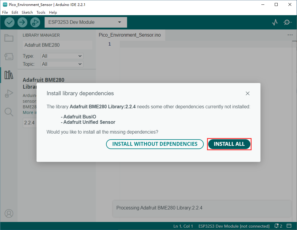
- Install Adafruit BME280 library
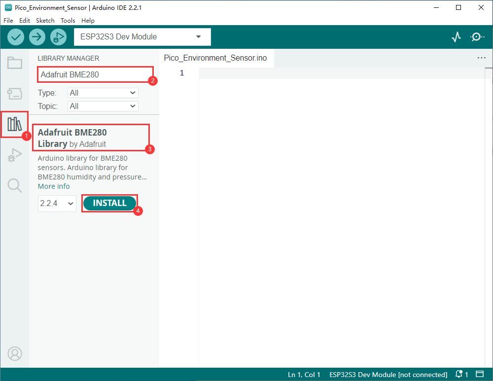
- Select INSTALL ALL
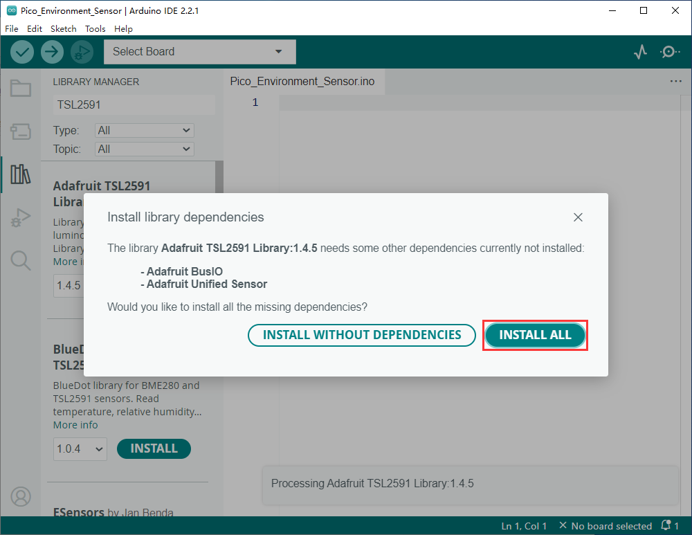
- Install Adafruit TSL2591 library

- Select INSTALL ALL
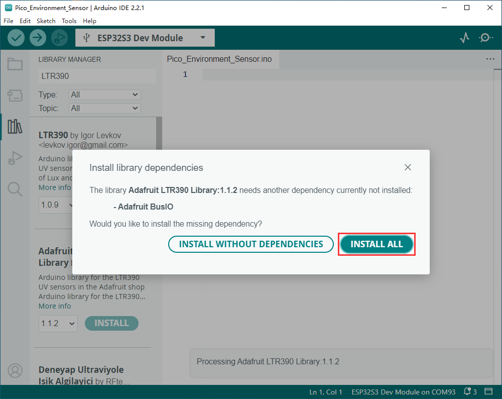
- Install Adafruit LTR390 library
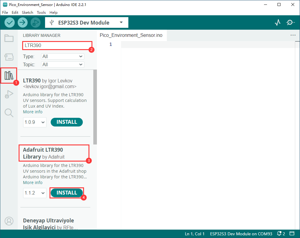
- Select INSTALL ALL
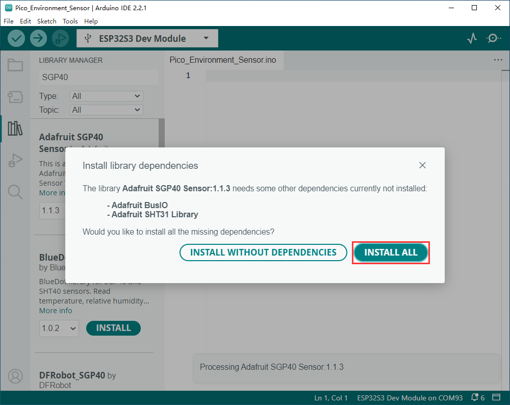
- Install Adafruit SGP40 library
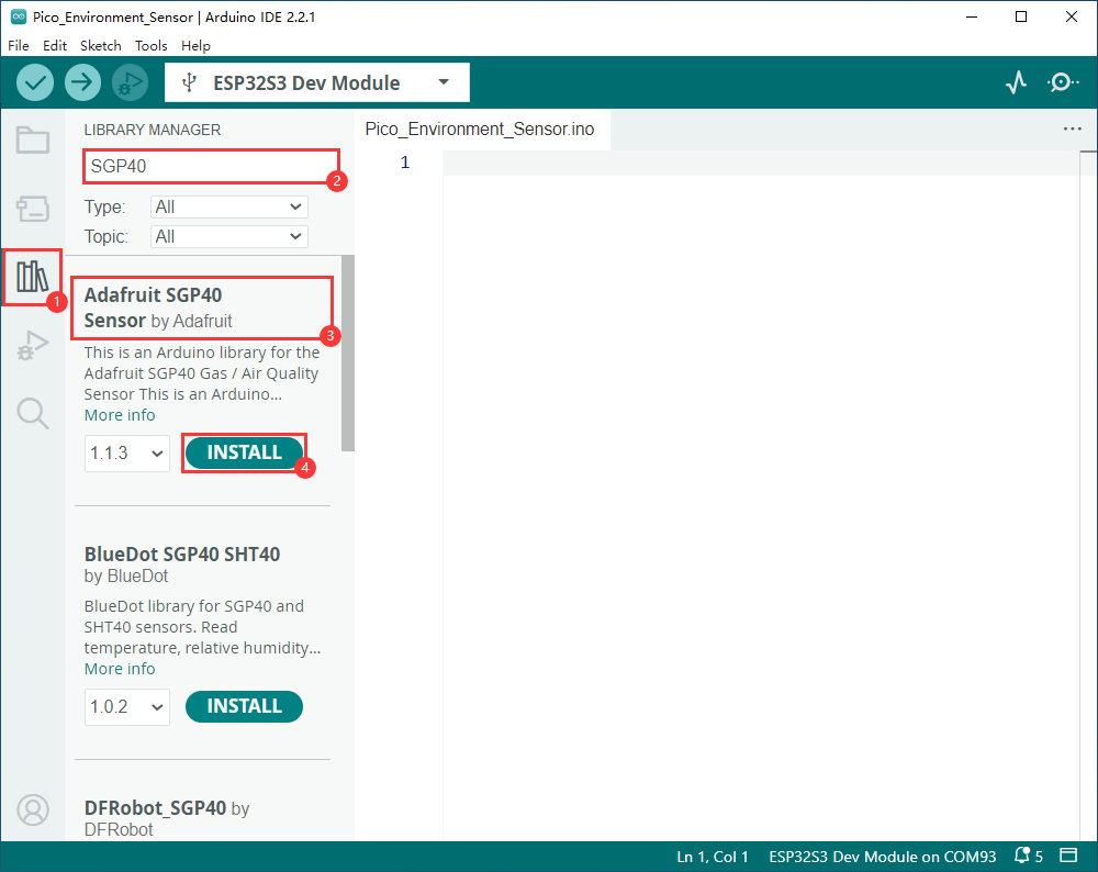
- Select INSTALL ALL
Tutorial
- Connect the Pico-Environment-Sensor device to ESP32-S3-Relay-6CH
- Download the provided Pico-Environment-Sensor Demo
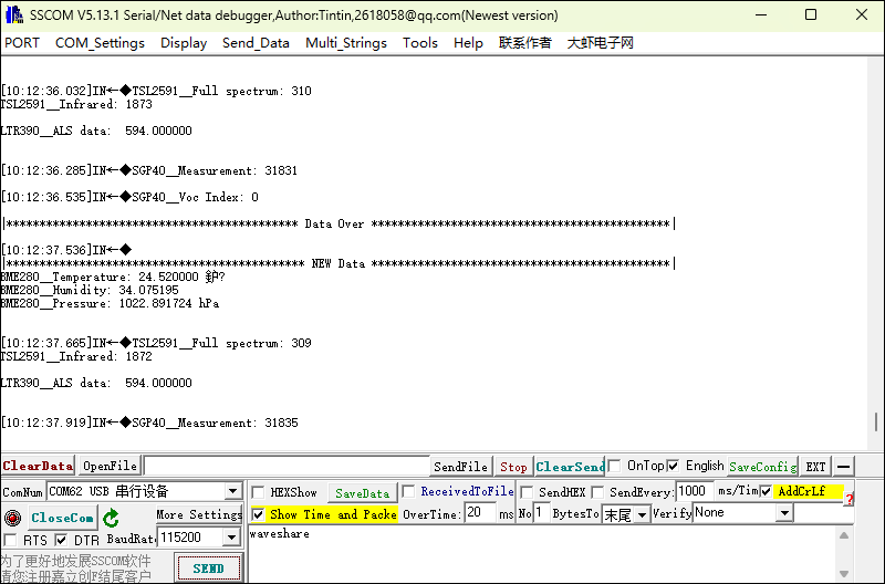
- In the main program, reference Environment_Sensor.c and Environment_Sensor.h
- Modify the program according to your needs, by default the demo runs and the results can also be viewed in the Arduino serial monitor
Extend RSRS232/RS485 Port with Pico Port
- Please note, when using Pico-2CH-RS485 to expand the RS485 port, only channel 1 is supported, and channel 0 cannot be used
- Use Pico-2CH-RS232 extend RS232 communication port
Tutorial
- Connect Pico-2CH-RS232 or Pico-2CH-RS485 device to ESP32-S3-Relay-6CH
- Connect Pico-2CH-RS485 device to USB TO RS232/485 Converter, in the same way as Pico-2CH-RS232

- Download the provided Pico-2CH-RS232 Demo (The demo applies to the above two devices)
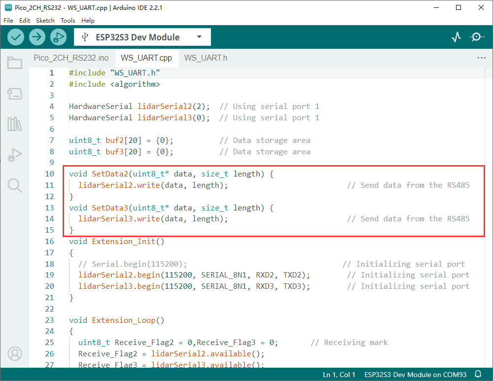
- Reference WS_UART.h in the main program
- Modify the demo according to the required operation
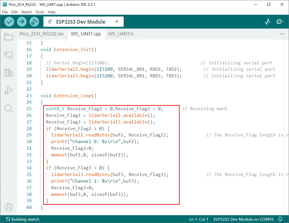
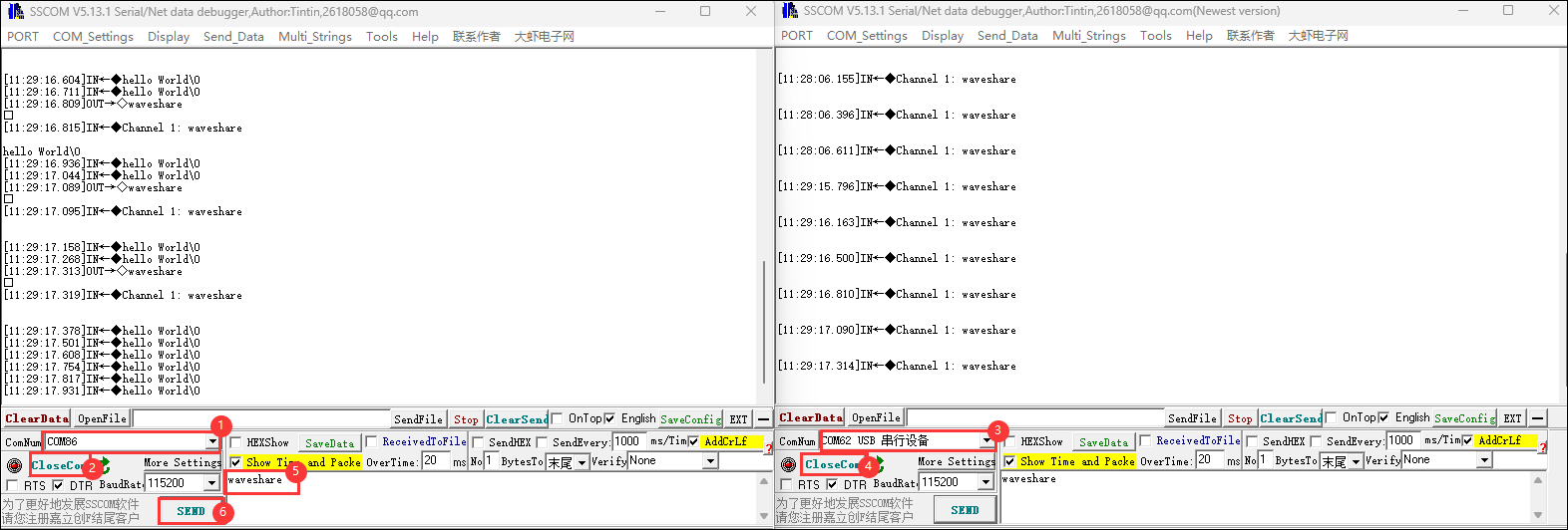
- Currently printing received characters in real time
- Call the initialization function Extension_Init() in setup
- After calling, data can be sent in the main loop program through the functions SetData2(uint8_t* data, size_t length) and SetData3(uint8_t* data, size_t length)
- Default program communication process: USB to RS485 converter communicates with ESP32-S3-Relay-6CH through Pico-2CH-RS485
Working with MicroPython
This section focuses on setting up the MicroPython development environment, primarily covering firmware flashing, installation, and the use of Thonny. For the installation part of Thonny, detailed explanations of the installation steps and usage instructions are provided, offering comprehensive and clear guidance for developers to build a MicroPython development environment.
Environment Setup
Download and Install Thonny
- Open the download page of Thonny official website and select the corresponding system and system bit to download
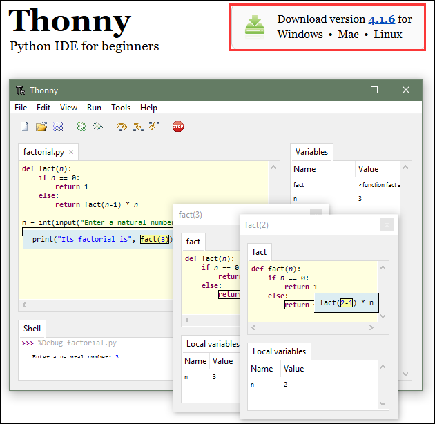
- Select the appropriate system and version, for example, with a 64-bit Windows, the mouse needs to be moved to the Windows section to display the corresponding information, then click to Download and Install
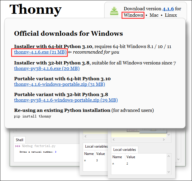
- The rest can be installed by default
Flash the Firmware
- Currently, the development board is developed using customized firmware, which is available in ESP32-S3-Relay-6CH Demo, note that the download address is the 0x00 location
- bin file path:
..\ESP32-S3-Relay-6CH-Demo\MicroPython\Firmware
- For a tutorial on flashing firmware, please refer to Flash Firmware Flashing and Erasing tutorial
The bin file is a file for testing the onboard function under the Firmware folder that is at the same level as the Arduino and MicroPython folders, and there is no need to flash it here
Thonny Usage
Select the development board and model
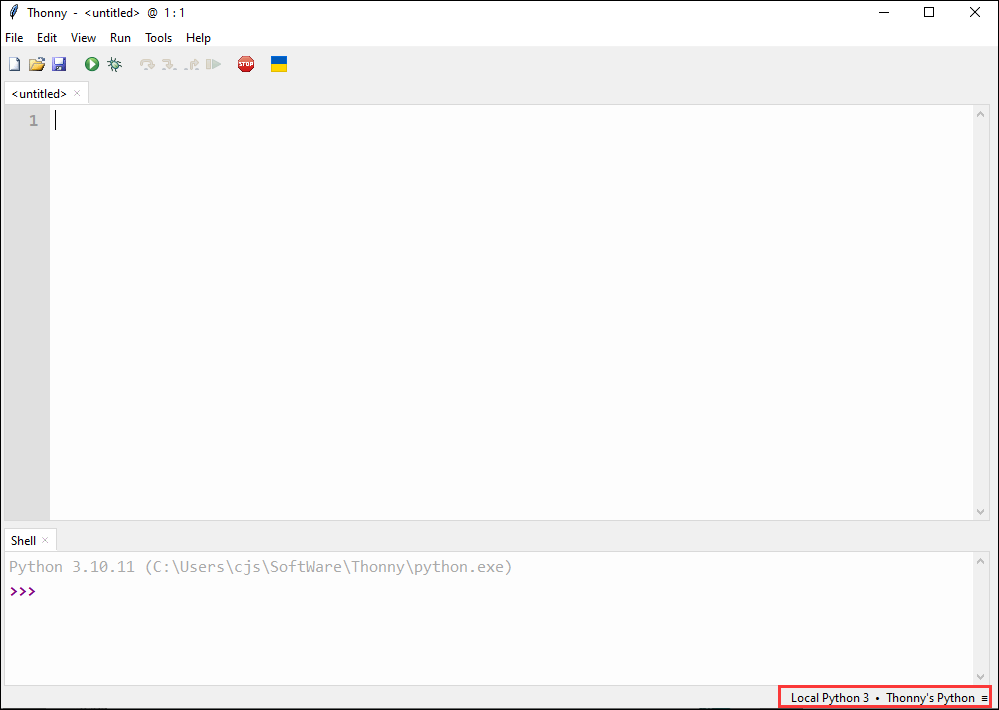
- Download and install the latest Thonny IDE, then open Thonny IDE -> Configure interpreter..., as shown in the following image
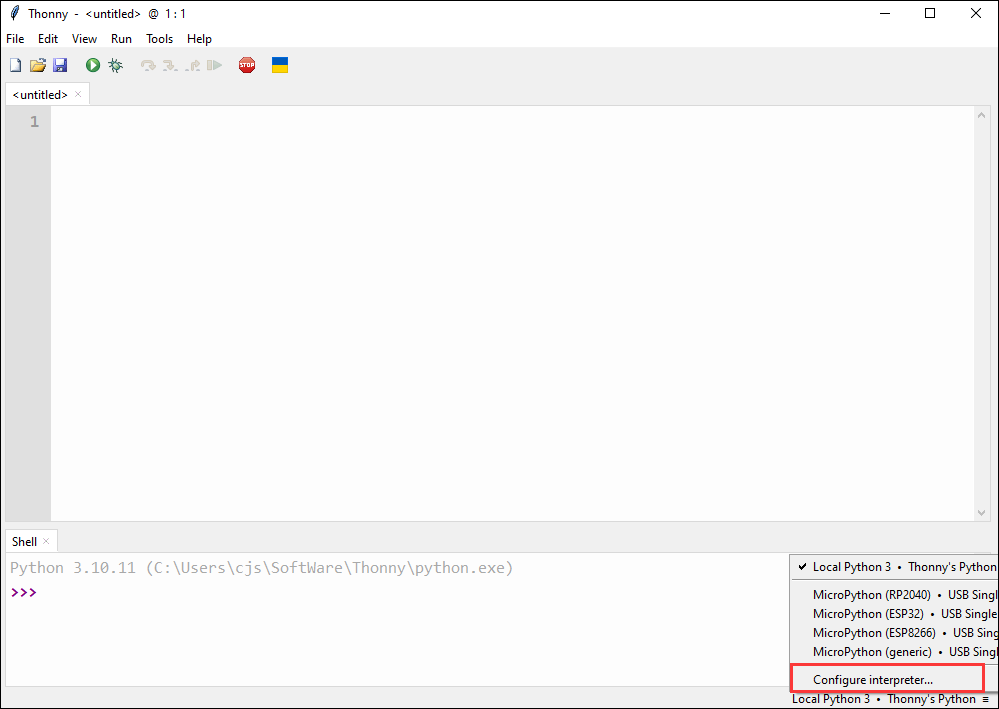
- Select ESP32 and the corresponding COM port

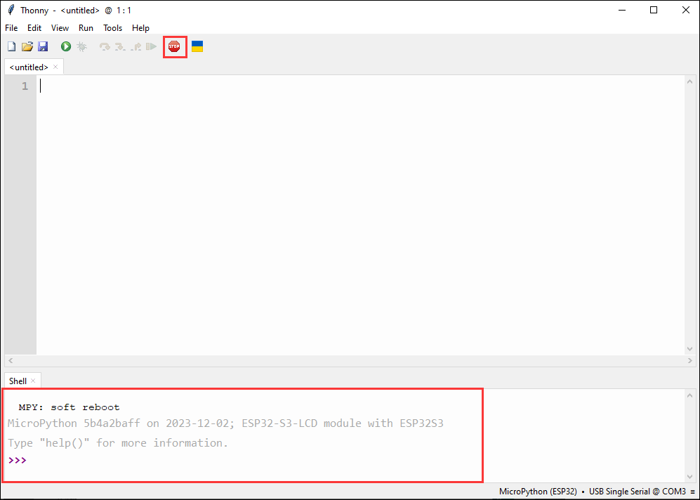
- Click this button to see the output statement in the shell, which indicates that the development board firmware has been successfully utilized
Upload demo
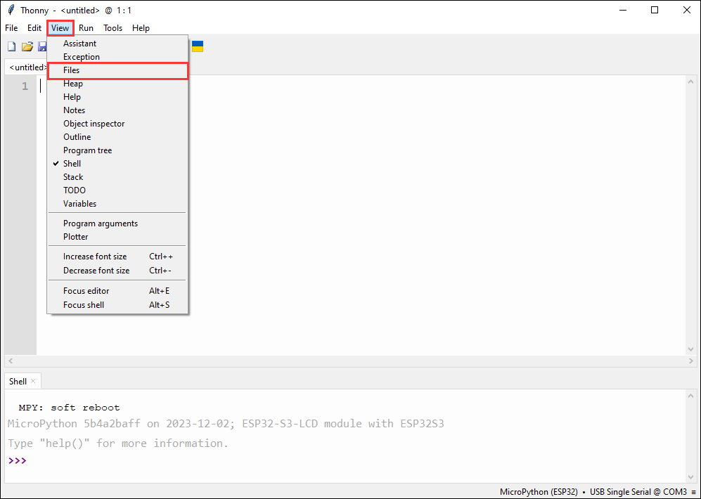
- How to find the desired demo, if there is no Files column at the beginning, we can find it in the View
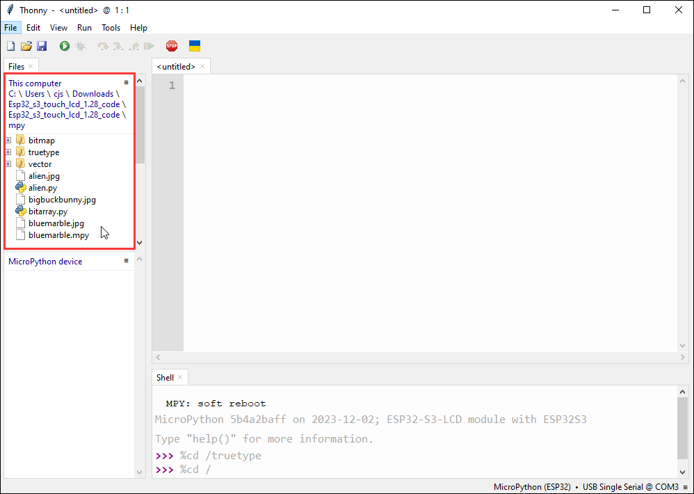
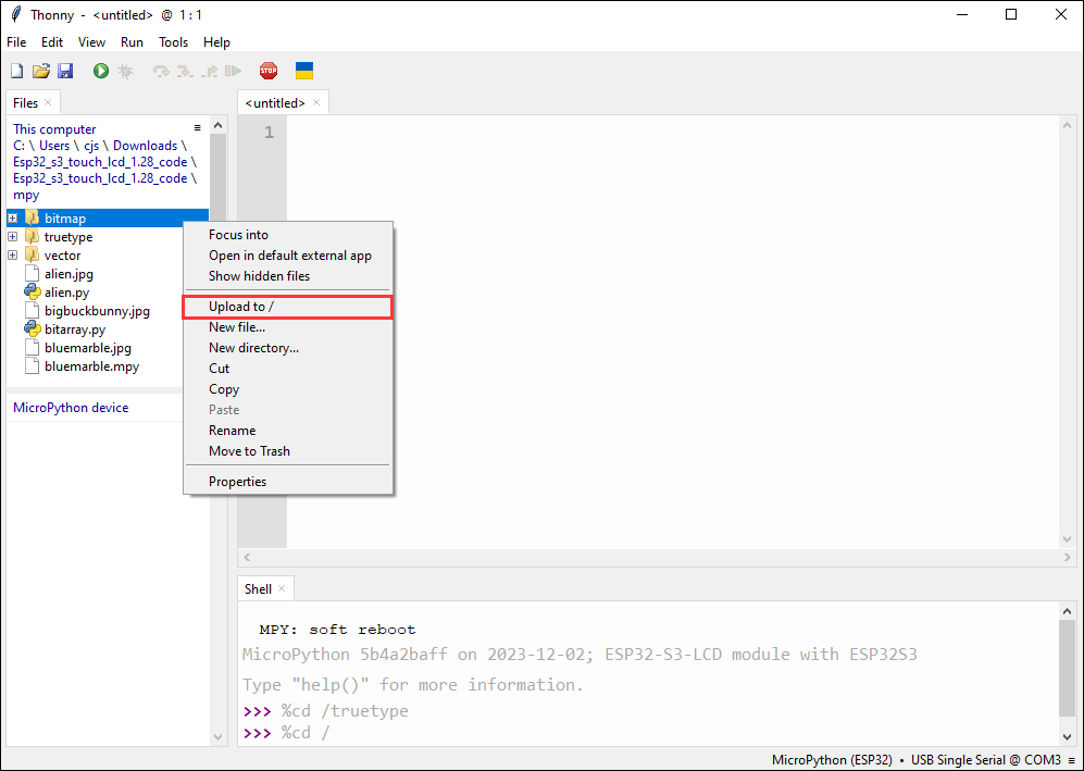
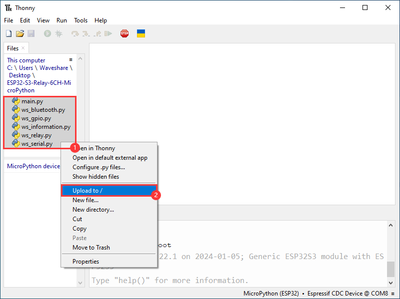
- Upload the local file to the development board, select the file, right-click with the mouse, find "Upload to/", and then download
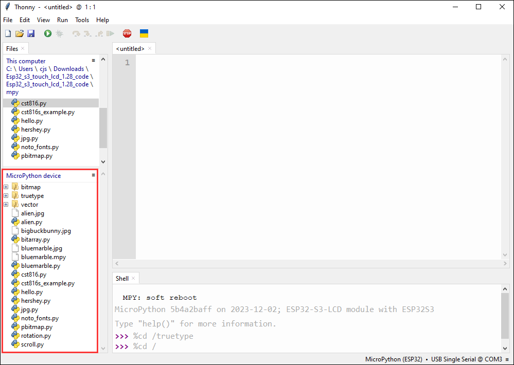
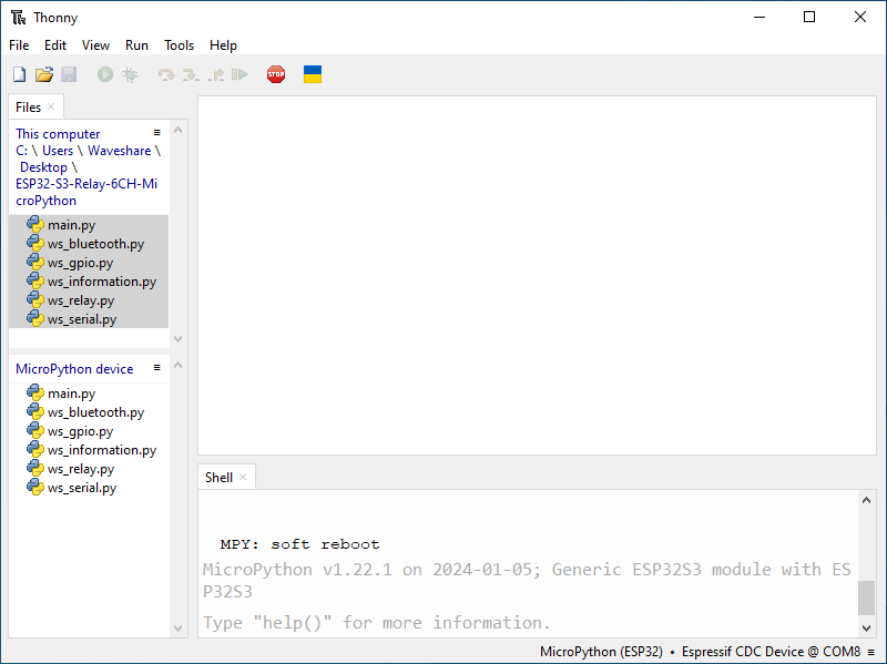
- The following is the interface where all downloads are completed, the downloaded file must be consistent with the file in the red box, otherwise it may fail to run
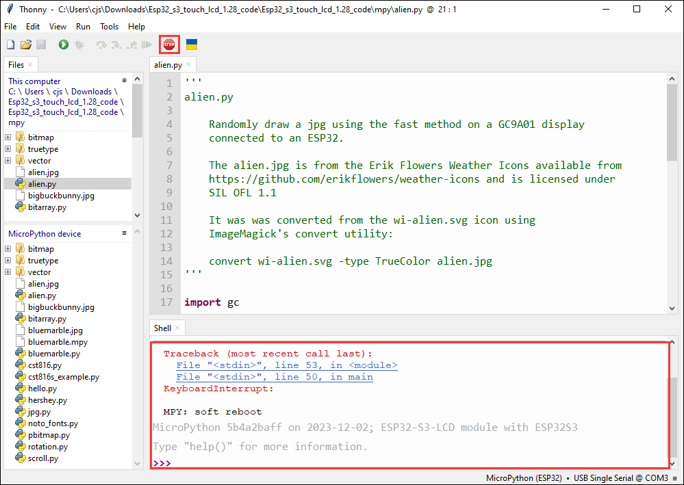
- Select the file with the .py suffix, and click the green button to flash and run
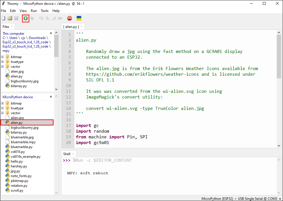
- When running another file, first click the red stop button, so that the other file can run normally
Demo

| Demo | Basic Description |
|---|---|
| main.py | Main function |
| ws_bluetooth.py | Bluetooth initialization and command parsing |
| ws_gpio.py | RGB, buzzer, relay initialization |
| ws_information.py | Global system parameter settings |
| ws_relay.py | Implement relay control |
| ws_serial.py | 8-ch relay extension |
Upload Demo
- Upload the local file to the development board, select the file, right-click with the mouse, find "Upload to/", and then upload
- The following is the interface where all uploads are completed, the uploaded file must be consistent with the file in the image, otherwise it may fail to run
Run Demo
- After running the demo
Flash Firmware Flashing and Erasing
- The current demo provides test firmware, which can be used to test whether the onboard device functions properly by directly flashing the test firmware
- bin file path:
..\ESP32-S3-Relay-6CH\Firmware\Factory bin
Working with Homeassistant
The product can be controlled online through the Homeassistant built on the Raspberry Pi, and the relevant operations can be found in Reference link
Resources
Schematic Diagram
Demo
Datasheets
ESP32-S3
Software Tools
Arduino
VScode
Thonny
Debugging tool
Other Resource Links
FAQ
- Long press the BOOT button, press RESET at the same time, then release RESET, then release the BOOT button, at this time the module can enter the download mode, which can solve most of the problems that can not be downloaded.
- It may be due to Flash blank and the USB port is not stable, you can long-press the BOOT button, press RESET at the same time, and then release RESET, and then release the BOOT button, at this time the module can enter the download mode to flash the firmware (demo) to solve the situation.
- It's normal for the first compilation to be slow, just be patient
- If there is a reset button on the development board, press the reset button; if there is no reset button, please power it on again
- Some AppData folders are hidden by default and can be set to show.
- English system: Explorer->View->Check "Hidden items"
- Chinese system: File Explorer -> View -> Display -> Check "Hidden Items"
- Windows system:
①View through Device Manager: Press the Windows + R keys to open the "Run" dialog box; input devmgmt.msc and press Enter to open the Device Manager; expand the "Ports (COM and LPT)" section, where all COM ports and their current statuses will be listed.
②Use the command prompt to view: Open the Command Prompt (CMD), enter the "mode" command, which will display status information for all COM ports.
③Check hardware connections: If you have already connected external devices to the COM port, the device usually occupies a port number, which can be determined by checking the connected hardware.
- Linux system:
①Use the dmesg command to view: Open the terminal.
①Use the ls command to view: Enter ls /dev/ttyS* or ls /dev/ttyUSB* to list all serial port devices.
③Use the setserial command to view: Enter setserial -g /dev/ttyS* to view the configuration information of all serial port devices.
- Install MAC Driver and flash again.
- Check the schematic diagram for different development boards with Type-C interfaces, and handle the output accordingly:
- For development boards with direct USB output, printf function is supported for printing output. If you want to support output via the Serial function, you will need to enable the USB CDC On Boot feature or declare HWCDC.
- For development boards with UART to USB conversion, both printf and Serial functions are supported for printing output, and there is no need to enable USB CDC On Boot.
- The factory demo is for learning only, if it is used for practical application, please optimize the demo logic by yourself.
- Please move the jumper cap to 120R and try again. Some RS485 devices require a 120R resistor to be connected in series.
Support
Monday-Friday (9:30-6:30) Saturday (9:30-5:30)
Email: services01@spotpear.com
ESP32-S3 Relay Industrial 6-Channel IOT WiFi Bluetooth RS485 Onboard Pico HAT interfaces Built-In Pr
[Tutorial Navigation]
- Overview
- Electrical Safety Precautions
- Usage Instructions
- Working with Arduino
- External Expansion
- RS485 Extended Relay Channels
- Extend Timer Switch Function with Pico Port
- Extend CAN Port with Pico Port
- Expand Environmental Monitoring Function
- Extend RSRS232/RS485 Port with Pico Port
- Working with MicroPython
- Flash Firmware Flashing and Erasing
- Working with Homeassistant
- Resources
- FAQ
- Question: After the module downloads the demo and re-downloads it, why sometimes it can't connect to the serial port or the flashing fails?
- Question: Why does the module keep resetting and flicker when viewed the recognition status from the device manager?
- Question: How to deal with the first compilation of the program being extremely slow?
- Question: How to handle the display "waiting for download..." on the serial port after successfully ESP-IDF flashing?
- Question: What should I do if I can't find the AppData folder?
- Question: How do I check the COM port I use?
- Question: Why does the program flashing fail when using a MAC device?
- Question: Why is there no output after successfully flashing the code with no issues?
- Question: Please note!
- Question: When controlling other devices using RS485, it is not sensitive or communication fails?
- Support