


- sales/support
Google Chat:---
- sales
+86-0755-88291180
- sales01
sales@spotpear.com
- sales02
dragon_manager@163.com
- support
tech-support@spotpear.com
- CEO-Complaints
zhoujie@spotpear.com
- Only Tech-Support
WhatsApp:13246739196
- Purchase/Shipping/Refund
WhatsApp:13424403025
RDK-X3-MD-Carrier-Board User Guide
Introduction
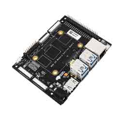
RDK X3 Module Carrier Board, as a supporting base board for X3 modules, provides a wealth of configurations and interfaces, including USB3.0, Ethernet, HDMI, MIPI CSI, MIPI DSI, 40PIN header, etc., making it convenient for users to verify and develop module functions.
System Installation
Version Description
Version 2.0: Based on RDK Linux open source code package, it supports a full range of hardware such as RDK X3 and X3 modules Version 1.0: An older version of RDK X3, only supports RDK X3 hardware, does not support the new version of RDK X3, the system image name is system_sdcard.img
Flash System
Click Download Image to enter the version selection page, select the corresponding version directory, and enter the file download page. This product only supports Version 2 images. For example, to download the system image of version 2.0.0, double-click 2.0.0, double-click release, and then click to download ubuntu-preinstalled-desktop-arm64.img.xz: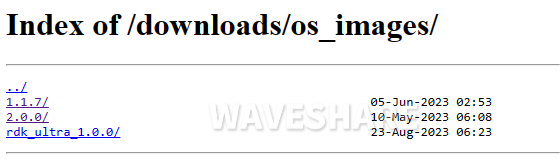
After the download is completed, extract the Ubuntu system image file, such as ubuntu-preinstalled-desktop-arm64.img The RDK X3 Module supports system boot from both eMMC and TF card modes
TF Card Flashing
- Insert the TF card into the card reader, connect the card reader to the computer, and open the balenaEtcher software after the TF card is recognized
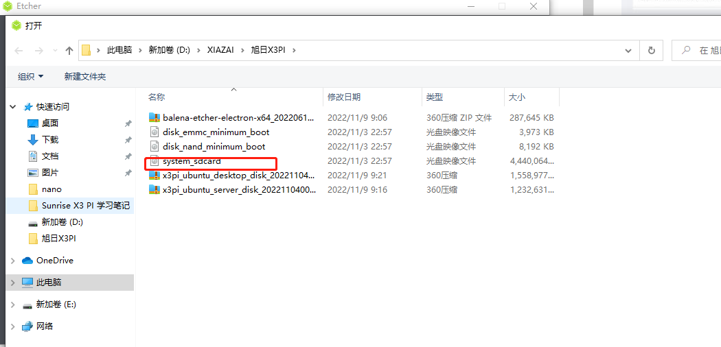
- Click Flash from file, select the system_sdcard.img file you just extracted
- Click Select target button and choose the disk corresponding to the TF card as the target storage device
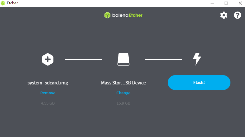
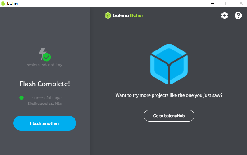
- Click Flash button to start flashing. When the tool prompts Flash Complete, it means that the TF card image is completed. Close balenaEtcher, remove the card reader from the computer, and take out the TF card
- Insert the TF card into the card reader, connect the card reader to the computer, and open rufus software after the computer recognizes the TF card
- Click the Select button, and in the pop-up file selection dialog, choose the system_sdcard.img image file extracted
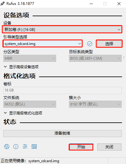
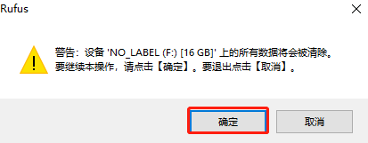
- Click the Start button, the software pops up a prompt box, click OK to start flashing the TF card image. If the following message pops up, click OK
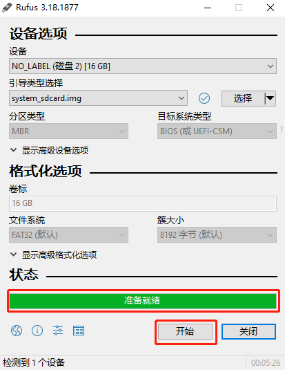
- When the software progress bar is complete and prompts Ready, it indicates that the TF card image has been successfully flashed. Close the software, remove the card reader, and take out the TF card
balenaEtcher Flashing Image
- Note: When using this software to flash, try to connect it directly to the USB port of the computer, and do not use external expansion, which may cause the flashing to fail.
rufus Flashing Image
eMMC Flashing
Drive Installation
You need to use the horizon hbupdate flashing tool, click to download driver. The hbupdate tool supports both Windows and Linux versions, starting with hbupdate_win64 and hbupdate_linux respectively.
Note: When extracting the compressed package, make sure that the extraction path does not contain spaces, Chinese characters, or special characters. For Windows PCs, you need to check whether the fastboot driver has been installed before using the flashing tool, please follow the steps below:
(1) Use the jumper cap to ground the Boot pin of the RDK X3 Module carrier board, and refer to the figure below for the pin position.
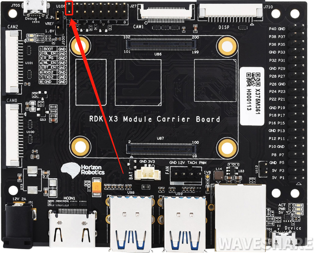
(2) Connect the Micro USB port of the carrier board to the computer through a USB cable, and refer to the following figure for the port location.
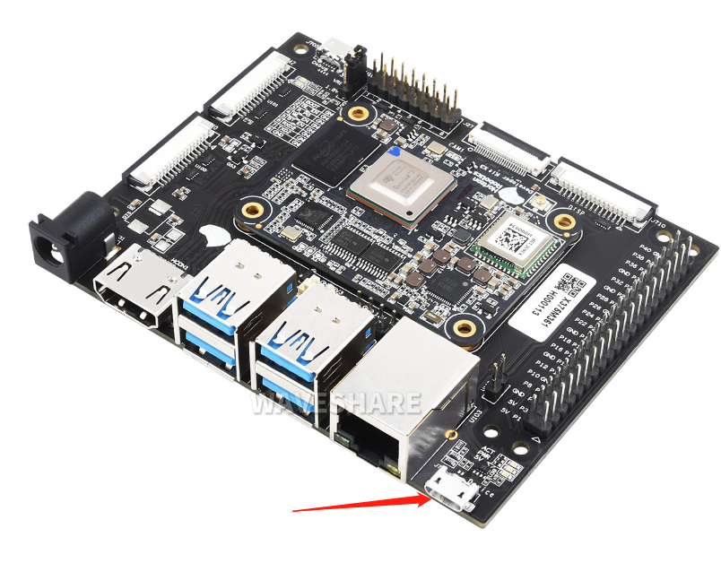
(3) Power on the device and observe the port status in the computer device manager. If an unknown USB download gadget device appears, the device driver needs to be updated. If it does not appear, the following steps can be skipped.

(4) Download and unzip the driver package android_hobot.zip, and download link is android_hobot.
(5) Enter the extracted directory, run 5-runasadmin_register-CA-cer.cmd as an administrator, and complete the driver registration.
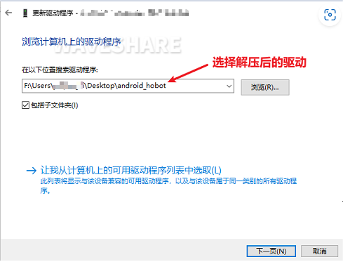
(6) Double-click the USB download gadget unknown device, select the driver package decompression directory, and click Next.
Flash System
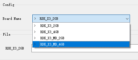
- RDK_X3_2GB: RDK X3, 2GB memory version, only supports flashing minimum system images
- RDK_X3_4GB: RDK X3, 4GB memory version, only supports flashing minimum system images
- RDK_X3_MD_2GB: RDK X3 Module, 2GB memory version
- RDK_X3_MD_4GB: RDK X3 Module, 4GB memory version
- When flashing the image, you need to ground the BOOT pin using a jumper cap. Refer to the functional control interface for the pin position
- Connect the Micro USB port to your computer, and the Android Device will be recognized in the PC Device Manager, as described in the previous section on installing the USB download driver
- After flashing, disconnect the power supply, disconnect the cable to the computer, unplug the BOOT pin jumper cap, and power it on again
- If the startup is normal, the ACT LED on the hardware will enter a state of two quick flashes followed by one slow flash
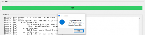
- When the image is flashed successfully, the tooltip is as follows:
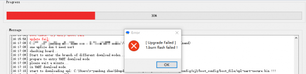
- If the image flashing fails, the tooltip is as follows, and you need to check whether the Android Device device exists in PC Device Manager
After confirming that the PC device manager displays the fastboot device as Android Device, run hbupdate.exe to open the flashing tool and follow the following steps for flashing:
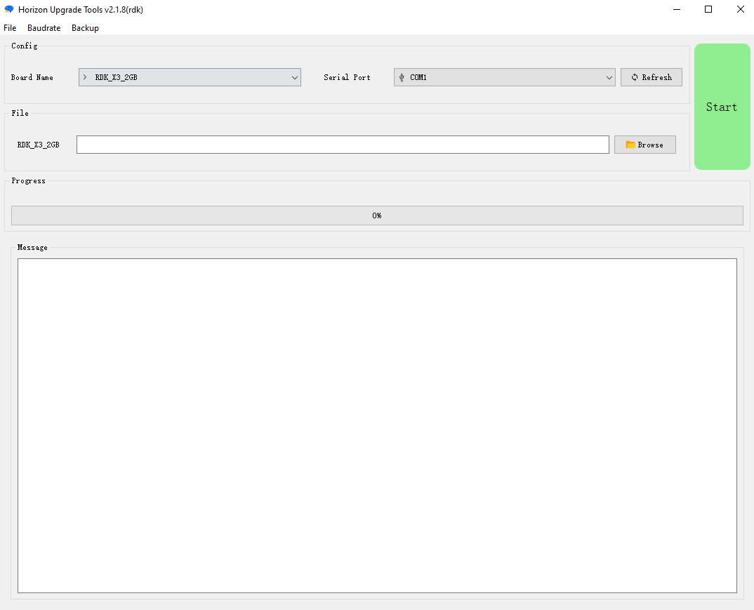
(1) Select the development board model, this is a mandatory option.
(2) Click Browse button to select the image file to be flashed, this is a mandatory option.

(3) Click Start button to begin the flashing process and proceed according to the pop-up prompts for flashing:
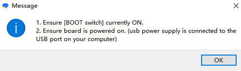
(4) Check the upgrade results
If the flashing process is interrupted, please repeat the steps above.
System Startup
The RDK X3 Module supports system boot from both eMMC and TF card modes: If the eMMC on the module has not been flashed with a system image, inserting a properly prepared TF card into the carrier board will allow the system to boot from the TF card.
If the eMMC on the module has already been flashed with a system image, you can switch between eMMC and TF card boot by following these steps.
1. By default, the system will boot from eMMC
2. Disable the boot of eMMC and switch to using TF card to boot the system, log in to the system, perform the following command to remove the boot flag of the second partition of eMMC, and restart the system to take effect:
sudo parted /dev/mmcblk0 set 2 boot off
sudo reboot
3. Under uboot, you will find that eMMC does not have a boot partition and look for the boot partition of the TF card, loading the system from the TF card. After logging into the system and executing the mount command, you can see that the root file system is mounted on the second partition of the TF card, and the config partition also uses the first partition of the TF card.
/dev/mmcblk2p2 on / type ext4 (rw,relatime,data=ordered)
/dev/mmcblk2p1 on /boot/config type vfat
Switch from TF card boot back to eMMC boot
When using a TF card to boot the system and a system has already been flashed onto the eMMC, execute the following command to restore booting from the eMMC, and the system will reboot to take effect.
sudo parted /dev/mmcblk0 set 2 boot on
sudo reboot
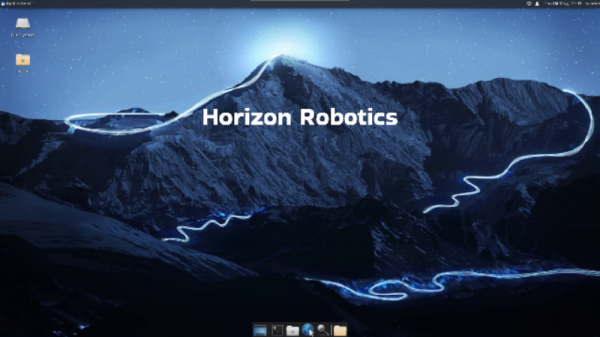
After the Ubuntu Desktop version system boots up, the system desktop will be output to the monitor through the HDMI port, as shown in the figure below:
Remote Login
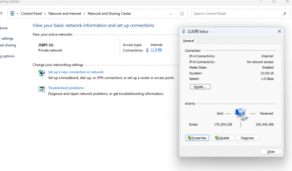
Wired Ethernet: The development board adopts static IP mode by default, with an IP address of 192.168.1.10, a mask of 255.255.255.0, and a gateway of 192.168.1.1
Wireless WiFi: The IP address of the development board is usually assigned by the router, and the IP address of the wlan0 network can be viewed through the ifconfig command on the device command line
Serial Port Login Operation
Method 1: putty serial port login
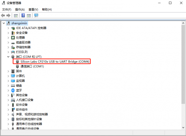
After the hardware is connected and the driver is installed, open the device manager, you will see the following ports:
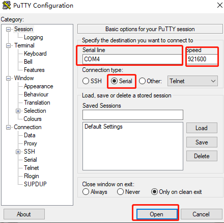
Open the putty software and configure it according to the figure below (based on the actual port identified).
When the development board is powered on, and information will be printed in the putty window, and then log in.
Enter the command
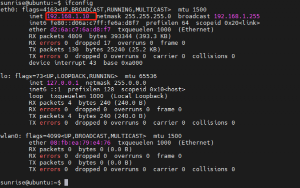
ifconfig
Obtain the IP address of the development board
ifconfig eth0 represents the Ethernet network (referring to the Ethernet cable), the newly flashed system defaults to 192.168.1.10
ifconfig wlan0 represents the WiFi network
Method 2: MobaXterm serial port login
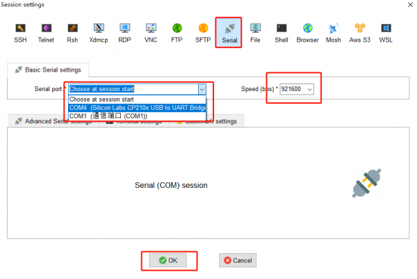
After the hardware is connected, power on the development board, open the MobaXterm software, and configure it according to the figure below.
When the development board is powered on, you will see the information printed in MobaXterm, and then log in.
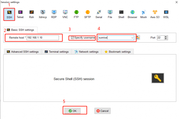
SSH Login
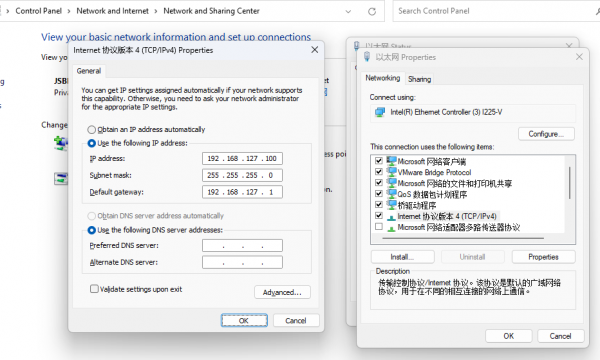
We need to configure the computer IP before SSH login
We have obtained the IP address of RDK X3 (192.168.127.10) from logging in via serial port.
To enable communication between the computer and RDK X3, the following operations need to be performed:
- The main steps for configuring a computer IP are as follows:
- Find the corresponding Ethernet device in the network connection and right-click to select Properties
- Find the Internet Protocol version 4 option and double-click to open it
- Fill in the corresponding network parameters in the red box in the following figure, and then click OK
- Install hostapd and isc-dhcp-server
sudo apt update sudo apt install hostapd sudo apt install isc-dhcp-server
Configure hostapd and enable it
sudo vim /etc/hostapd.conf
For password-less hotspots, please add the following configuration:
interface=wlan0 driver=nl80211 ctrl_interface=/var/run/hostapd ssid=Sunrise channel=6 ieee80211n=1 hw_mode=g ignore_broadcast_ssid=0
For hotspot configurations with passwords, please add the following content:
interface=wlan0 driver=nl80211 ctrl_interface=/var/run/hostapd ssid=Sunrise channel=6 ieee80211n=1 hw_mode=gignore_broadcast_ssid=0 wpa=2 wpa_key_mgmt=WPA-PSK rsn_pairwise=CCMP wpa_passphrase=12345678
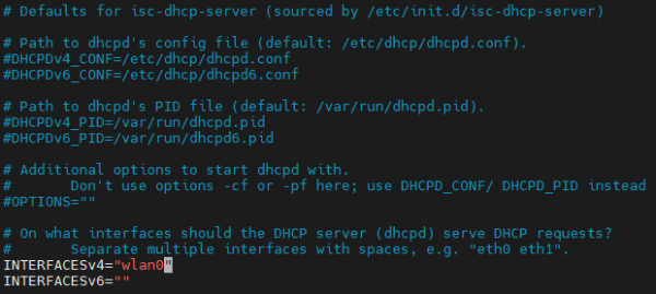
- Configure isc-dhcp-server in terminal input
sudo vim /etc/default/isc-dhcp-server
Define the network interface to be used as follows, save and exit: INTERFACESv4="wlan0"
Enter in the terminal:sudo vim /etc/dhcp/dhcpd.conf
Comment out the following fields:
authoritative;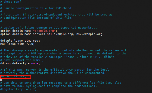
Then enter:sudo vim /etc/dhcp/dhcpd.conf
Add the following configuration at the end of the file:
subnet 10.5.5.0 netmask 255.255.255.0 { range 10.5.5.100 10.5.5.254; option subnet-mask 255.255.255.0; option routers 10.5.5.1; option broadcast-address 10.5.5.31; default-lease-time 600; max-lease-time 7200;} - Stop the wpa_supplicant service and restart wlan0
Note: From this step onwards, it is best to enter superuser mode
For the first time entering the super user, please follow the steps below:
Set a password to enter the root user:sudo passwd root
Then enter the password 3 times, set the password, confirm the password, and confirm it again
Enter root user:su root / sudo su
Then enter the password
Exit root user:su sunrise
Run the following command to stop the wpa_supplicant service and restart WLAN0
systemctl stop wpa_supplicant
- Start hostapd service
sudo hostapd -B /etc/hostapd.conf
The following information will be printed:
root@ubuntu:~# sudo hostapd -B /etc/hostapd.conf Configuration file: /etc/hostapd.conf Using interface wlan0 with hwaddr 08:e9:f6:af:18:26 and ssid "sunrise" wlan0: interface state UNINITIALIZED->ENABLED wlan0: AP-ENABLED
- Configure the IP and network segment of wireless interface wlan0. Note that it should be consistent with the above configuration.
sudo ifconfig wlan0 10.5.5.1 netmask 255.255.255.0
- When you turn on the DHCP server, connecting to the hotspot will assign an IP address to the client from 10.5.5.100 to 10.5.5.255.
sudo systemctl start isc-dhcp-server sudo systemctl enable isc-dhcp-server
Open your phone and connect to the hotspot named Sunrise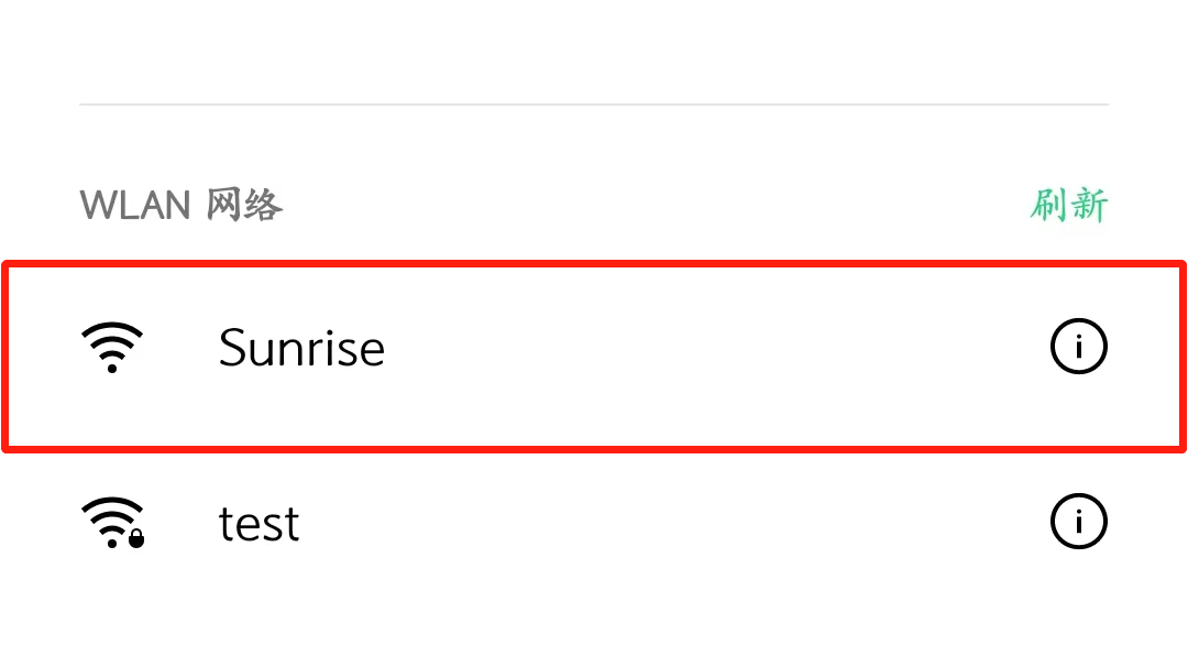
- Switch back to Station mode
# Stop hostapd killall5 -9 hostapd # Clear the address of wlan0 ip addr flush dev wlan0 sleep 0.5 ifconfig wlan0 down sleep 1 ifconfig wlan0 up # Restart wpa_supplicant systemctl restart wpa_supplicant # Connect to a hotspot, for specific operations, please refer to the previous section "Wireless Network" wifi_connect "JSBPI" "waveshare0755"
- Modify the /etc/systemd/resolved.conf file:
sudo vim /etc/systemd/resolved.conf
Add DNS server address:
DNS=8.8.8.8 114.114.114.114
- Enable new DNS configuration:
sudo systemctl restart systemd-resolved sudo systemctl enable systemd-resolved sudo mv /etc/resolv.conf /etc/resolv.conf.bak sudo ln -s /run/systemd/resolve/resolv.conf /etc/
MobaXterm Login
Note: The username and password must be entered within 60 seconds upon startup. If not completed, you can try again within the next 60 seconds.
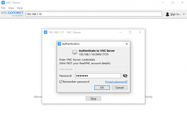
VNC Login
Open the VNC software, enter the IP address of RDK X3 in the address bar, press Enter, and configure as shown in the following image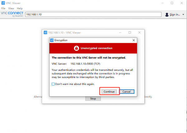
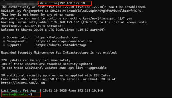
Command Line Login
Open the terminal in the Ubuntu virtual machine and input:
ssh sunrise@192.168.127.10
Demo
GPIO Call
In the /app/40pin_samples/ directory of the development board, a variety of functional test codes for 40PIN pins are preset, including gpio input/output tests, PWM, I2C, SPI, UART, and other tests. All test programs are written in python and details can be found in the 40PIN feature usage.
Demo of Image Classification Algorithm
The test_mobilenetv1.py demo is installed on the development board to test the functionality of the MobileNet v1 image classification algorithm.
The demo reads the static image zebra_cls.jpg as input for the model and outputs the classification result cls id in the command line terminal: 340 Confidence: 0.991851
cd /app/pydev_demo/01_basic_sample/
sudo ./test_mobilenetv1.py
USB Camera Usage
The development board is equipped with the usb_camera_fcos.py demo for testing the data path of the USB camera. This demo captures image data from the USB camera in real-time, runs the object detection algorithm, and then outputs the image data and detection results via the HDMI interface.
Connect the USB camera to the development board, confirm that the /dev/video8 device node is generated
Connect the development board to the display using an HDMI cable
cd /app/pydev_demo/02_usb_camera_sample/
sudo python3 ./usb_camera_fcos.py
After the program is executed, the display will show the camera feed and the results of the target detection algorithm (target type, confidence).
MIPI Camera Usage
Connect the MIPI camera module to the MIPI CSI interface of the development board, connect the development board and display via an HDMI cable, and execute the following commands:
 cd /app/pydev_demo/03_mipi_camera_sample/
 sudo python3 ./mipi_camera.py
After the program is executed, the display will show the camera feed and the results of the target detection algorithm (target type, confidence) in real time
System Configuration
System Update
For system security and stability reasons, it is recommended that users update the system through APT commands after installing the system.
In the /etc/apt/source.list file, a list of software sources for the APT command is saved. Before installing software, you need to update the package list using the apt command.
First, open the terminal command line and enter the following command:
sudo apt update
Next, upgrade all installed packages to the latest versions with the following command:
sudo apt full-upgrade
Note: It is recommended to use full-upgrade instead of the simple upgrade command, as this will also update the dependent packages when related dependencies change.
When running the sudo apt full upgrade command, the system will prompt for data download and disk usage size, but apt will not check if the disk space is sufficient. It is recommended that users use
df -h
command to check manually. Additionally, the deb files downloaded during the upgrade process will be saved in the /var/cache/apt/archives directory, and users can use
sudo apt clean
command to delete cache files to free up disk space.
After executing full-upgrade, you may reinstall the driver and upgrade the RDK X3 kernel, so it is recommended to restart the device with the following command:
sudo reboot
Cable and Network Configuration
The network configuration for the development board is saved in the /etc/network/interfaces file When saving in the vim editor, please first press the Esc key, then input
:wq!
The nano editor is recommended, and the installation command is as follows:
sudo apt update
sudo apt-get install nano
Static IP Modification
You can modify the static IP configuration by modifying fields such as address, netmask, and gateway
For example:
sudo vim /etc/network/interfaces
# interfaces(5) file used by ifup(8) and ifdown(8)
# Include files from/etc/network/interfaces.d:
source-directory /etc/network/interfaces.d
auto eth0
iface eth0 inet static
    address 192.168.1.10
    netmask 255.255.255.0
    gateway 192.168.1.1
    metric 700
After the modification is completed, enter in the command line
sudo systemctl restart NetworkManager
to make the configuration take effect.
Restart and update network frequency band:
sudo reboot
Modify DHCP Configuration
DHCP (Dynamic Host Configuration Protocol) is usually used in large LAN environments, and its main function is to centrally manage and assign IP addresses, so that hosts in the network environment can dynamically obtain IP addresses, gateway addresses, DNS server addresses and other information, and can improve the utilization rate of addresses. The DHCP network configuration for the development board is saved in the /etc/network/interfaces file. By modifying the configuration related to eth0, you can change the DHCP mode. For example, you can input:
sudo vim /etc/network/interfaces
Modify the following:
source-directory /etc/network/interfaces.d
auto lo
iface lo inet loopback
auto eth0
iface eth0 inet dhcp
    metric 700
After the modifications are completed, input the command line, enter the following command in the command line:sudo systemctl restart NetworkManager
to make the configuration take effect.
Restart and update network frequency band:
sudo reboot
Modify MAC Address Configuration
To modify the default MAC address of the development board, you can add pre-up configuration information to the /etc/network/interfaces file to specify the MAC address the user needs, for example:
sudo vim /etc/network/interfaces
Modify the following:
# interfaces(5) file used by ifup(8) and ifdown(8)# Include files from
/etc/network/interfaces.d:
source-directory /etc/network/interfaces.d
auto eth0
iface eth0 inet static
    address 192.168.1.10
    netmask 255.255.255.0
    gateway 192.168.1.1
    pre-up ifconfig eth0 hw ether 00:11:22:9f:51:27
After the modifications are completed, input the command line, enter the following command in the command line:
sudo systemctl restart NetworkManager
to make the configuration take effect.
Restart to update network frequency band
sudo reboot
Wireless Network Configuration
Ubuntu Desktop Version System
After connecting to WiFi, as shown in the figure below, the position will change to WiFi style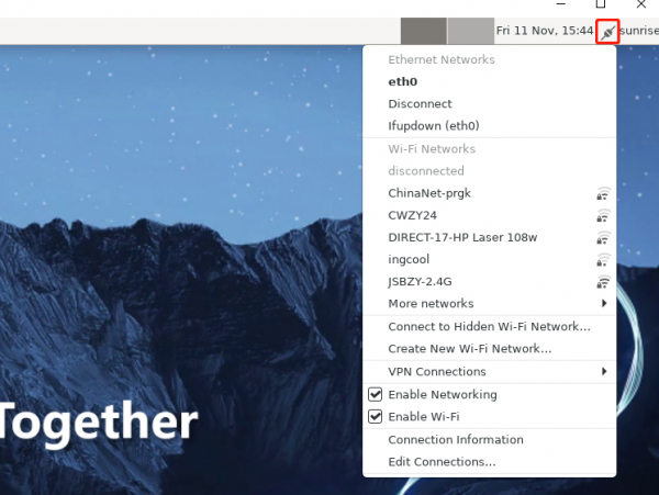
Ubuntu Server Version System
Enter WiFi scan command:
sudo nmcli device wifi rescan
If there is an error message: Scanning not allowed immediately following previous scan, it indicates that the scan is too frequent. Please wait for a moment before scanning again
Display the scanned WiFi:
sudo nmcli device wifi list
Connect to WiFi using command:
sudo wifi_connect "SSID" "PASSWD"
sudo wifi_connect "JSBPI" "waveshare0755"
If the following command is returned, it indicates success. If other problems occur, follow the error prompt to make modifications
Device 'wlan0' successfully activated with '********-****-****-****-************'
If an Error message appears: No network with SSID 'WiFi-Test' found, it means that the hotspot has not been refreshed yet and you can execute:
sudo nmcli device wifi rescan
command to rescan.
Wireless Network Soft AP
A WiFi soft AP can be understood as a WiFi hotspot on your phone.
The Wi-Fi of AP6212 supports both soft AP and Station modes. By default, it operates in Station mode. If you want to use the soft AP function, please configure it according to the following steps.
DNS Service
- DNS (Domain Name Server) is a server that performs the conversion of domain names to their corresponding IP addresses. The development board DNS is configured through the /etc/systemd/resolved.conf file management. Users can complete DNS-related configurations by modifying this file, by removing the # sign in front of #DNS:
CPU Frequency Scaling Strategy
- The development board manages the CPU operating state using the CPUFreq driver in the Linux kernel, with the default state being ondemand mode. In this mode, the CPU dynamically adjusts its frequency based on the load to achieve power-saving purposes. Users can force the CPU to operate at the maximum frequency of 1.2GHz using the following command:
sudo bash -c 'echo performance > /sys/devices/system/cpu/cpufreq/policy0/scaling_governor'
The development board provides overclocking functionality in the System. It can increase the CPU highest frequency from 1.2GHz to 1.5GHz. The configuration command is as follows:
sudo bash -c 'echo 1 > /sys/devices/system/cpu/cpufreq/boost'
Note that CPU overclocking may cause stability issues. If stability problems occur, you need to disable the overclocking function, as follows:
sudo bash -c 'echo 0 > /sys/devices/system/cpu/cpufreq/boost'
Special Declaration: CPU overclocking is limited to attempts by developer Geek. Before overclocking, proper cooling measures must be ensured for the chip to guarantee that the junction temperature of the chip remains below 95 degrees Celsius during long-term operation, avoiding chip failure due to prolonged high-temperature operation. CPU overclocking can also cause some chip reliability issues that are not yet predictable, so developers should be cautious. The command to check the current junction temperature of the chip, CPU operating frequency, BPU operating frequency, and BPU utilization is as follows:
sudo hrut_somstat
Bluetooth
- Call the script to complete initialization
- Reset Bluetooth
- Create messagebus users and user groups, which are required when the dbus-daemon program runs
- Run brcm_patchram_plus to complete the driver loading and firmware loading of Bluetooth
- Loop check if the /sys/class/Bluetooth/hci0 directory exists and confirm that the Bluetooth driver is running normally
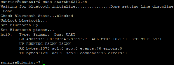
- Done setting line discpline appears to indicate that Bluetooth is successfully enabled
- Perform hciconfig hci0 up to complete Bluetooth Link Up
- Perform hciconfig hci0 piscan for Bluetooth scanning, this step can be removed according to the situation
- As shown in the figure:
- After successful execution, confirm that the following processes are running properly:
- exit : Exit the bluetoothctl interactive interface
- help : Get the list of commands supported by bluetoothctl
- Connect : Connect BLE device, input "connect BLE MAC" to connect to a specified BLE device. Upon successful connection, it will prompt "connect successfully". After the first successful connection, it will display all the properties supported by the BLE device; if the specified device cannot be found, it will prompt "not available"
- disconnect: Disconnect the device
sudo startbt6212.sh
The script call initialization completed the following tasks:
cd /usr/bin
*ls #Check if there are dbus-daemon and brcm_patchram_plus files
*cd ..#Return to the previous level
*cd lib/bluetooth #Enter directory
*ls #Check if there are Bluetooth files
Command Line Operation
Enter the Bluetooth configuration interface in interactive mode
sudo bluetoothctl
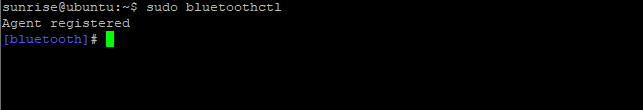
Indicates that Bluetooth has been recognized
Input show to view Bluetooth details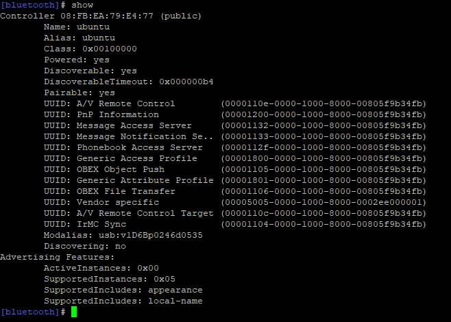
Note the Powered (on power) and Discoverable (can be discovered) states of Bluetooth
power on          Enable Bluetooth
power off          Disable Bluetooth
discoverable on          Make the device detectable
discoverable off          Make the device undetectable
scan on          Start scanning for nearby Bluetooth devices
scan off          Stop scanning
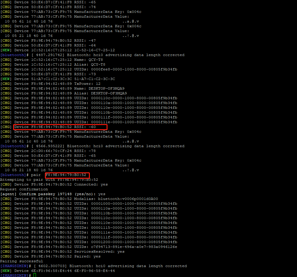
Pair the corresponding Bluetooth device and enter yes as prompted
pair [targetMAC]
For example: pair 9C:5A:81:3E:97:4C
After pairing is successful, use the command to connect automatically next time
trust [targetMAC]
For example: trust 9C:5A:81:3E:97:4C
Bluetoothctl command extension
For more operations, please visit the BlueZ website :
http://www.bluez.org/
Desktop Software Operation
Select the icon or menu bar in the upper right corner to operate Bluetooth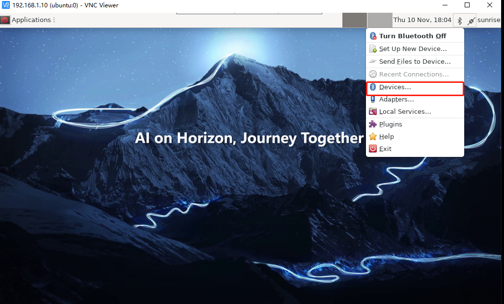
Or click Applications.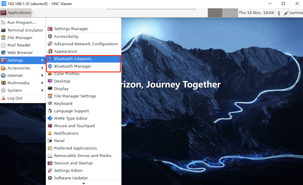
Bluetooth Adapters: Used to configure local Bluetooth settings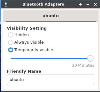
Bluetooth Manager: Used to scan and connect Bluetooth devices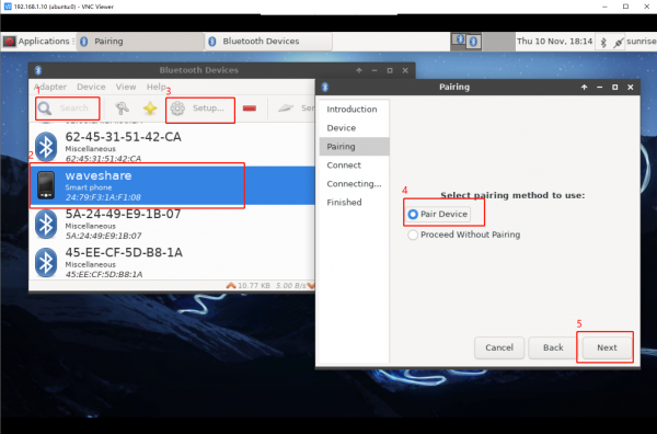
Expansion
Check if the Bluetooth module is recognized:
hciconfig -a
Check the address of the Bluetooth module:
hcitool dev
Activate Bluetooth:
sudo hciconfig hci0 up
In this test, the Bluetooth module is set as the server and does not require a pairing code:
hciconfig hci0 noauth
Edit the file and enable the Bluetooth device:
sudo vi /etc/systemd/system/dbus-org.bluez.service
Find ExecStart=/usr/lib/bluetooth/bluetoothd, modify and add it as:
ExecStart=/usr/lib/bluetooth/bluetoothd -C
ExecStartPost=/usr/bin/sdptool add SP
File Transfer
samba
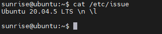
Operating Instructions
cat /etc/issue
sudo apt-get upgrade
sudo apt-get update
sudo apt-get dist-upgrade
sudo apt-get install samba samba-common
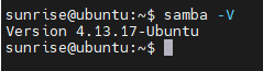
Check if the samba service has been installed successfully:
samba -V (If the following version number appears, it means samba service is already installed)
sudo mkdir /home/share
sudo chmod 777 /home/sunrise
Note: This needs to correspond to the configuration file Add Samba users for authentication by other users or devices. The users to be added here must exist in the system accounts; otherwise, the addition will fail
sudo smbpasswd -a sunrise
Then enter the access password
Create a username mapping file and configure (define according to the configuration file)
sudo vim /etc/samba/smbusers
Paste and save in the file
share= "network username"
The usage of the smbpasswd command
The usage of the smbpasswd command
smbpasswd -a    Add a user (the user to be added must be a system user)
smbpasswd -d    Freeze the user, that is, the user cannot log in
smbpasswd -e    Restore a user, unfreeze a user, and allow frozen users to log in
smbpasswd -n    Set the user's password to empty. Write null passwords -true in global
smbpasswd -x    Delete a user
# View samba user list (root permission required)
pdbedit -L
# Manage samba users (users are already created in the system) (root permission required)
smbpasswd -h    #View the list of supported commands
#Check the log status in case of abnormalities
cat /var/log/samba/log.%m
sudo cp /etc/samba/smb.conf /etc/samba/smb.conf.bak
If there is a mistake here, you can use the previously backed-up file to restore it
sudo vi /etc/samba/smb.conf
Add the following content at the end of the smb.conf configuration file:
[global]- workgroup = WORKGROUP
unix charset = UTF-8
dos charset = cp936
guest ok = no
security = user
username map = /etc/Samba/smbusers
[share]
- comment = Shared Folder with username and password
path = /home/sunrise/
public = no
valid users = sunrise
browsable = no
create mask = 777
directory mask = 777
force user = sunrise
force group = sunrise
available = yes
browseable = yes
writable = yes
The significance of the above operations: [global] Create a workgroup, set the workgroup or domain that the Samba Server should join
workgroup = WORKGROUP
To prevent garbled Chinese directories, depending on your local context, UTF-8 may need to be changed to cp936
display charset = UTF-8
unix charset = UTF-8
dos charset = cp936
Whether guest users are allowed to access
guest ok = no
Note: If #security exists, modify it; if not, create it
security = user
For security mode, we set the user security level
security = user
Explanation: Used to define username mapping, such as changing root to administrator, admin, etc. However, it should be defined in the smbusers file beforehand. For example: root = administrator admin, you can use administrator or admin users instead of root to log in to Samba
username map = /etc/Samba/smbusers
The share name, that is, the shared label, is the name of the share you see on your computer (Note that the path of the network map is the name of this tag, not the name of the shared path
[share]
Shared content description
comment = Shared Folder with username and password
Shared folder path
path = /home/sunrise/
Indicates whether anonymous access to the shared directory is allowed
public = no
The configured Samba access accounts specifies the users who can access it
valid users = sunrise
Indicates whether the directory can be displayed in Windows Explorer
browsable = no
Specifies the attributes of the newly created file
create mask = 777
Specifies the attributes of the newly created directory
directory mask = 777
force group and force user specify who the owner and group owner of the created files or folders are
If both of these values are empty, it indicates that the owner and group owner are the creator of the file. If set values, such as force
group=sunrise
force user=sunrise, no matter who created the file or folder, the owner is sunrise and the sunrise group.
force user forcibly sets the owner of the created file. If I have a directory that allows the guest to write, then the guest can delete it.
If I use force user=sunrise to force the owner of the file to be sunrise, and limit the create mask = 0755, then guests cannot delete it.
force user = sunrise
force group = sunrise
available is used to specify whether the shared resource is available
available = yes
Share path read permission, it sets whether the share can be browsed. If no, it means hidden, and needs to be accessed through "//ip/share directory"
browseable = yes
Shared path write permission
writable = yes
sudo service smbd restart or /etc/init.d/samba restart
Some version paths are not /etc/init.d/samba. You can try using:
sudo /etc/init.d/samba restart
#sudo /etc/init.d/samba-ad-dc restar
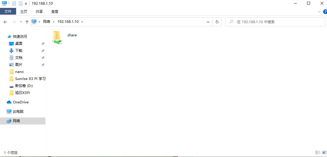
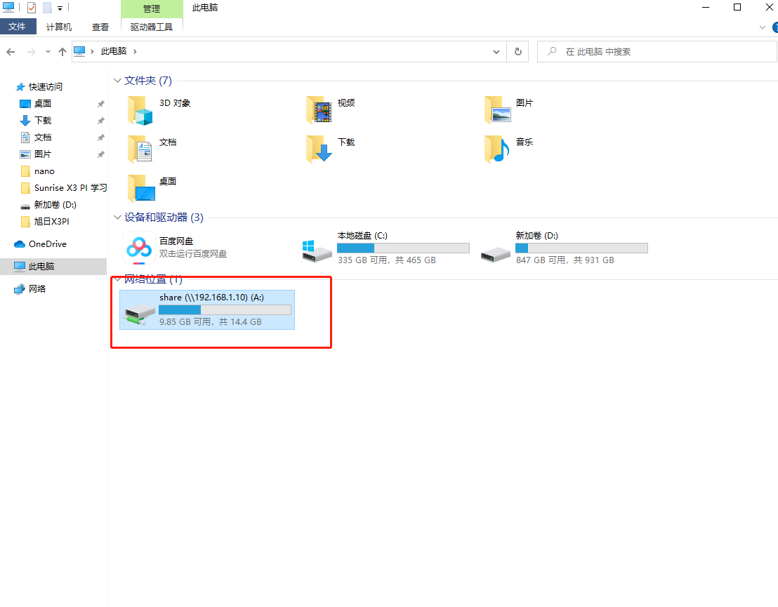
If frequently used shared paths are mapped as a disk in Windows, you don't need to enter the IP address every time. However, if the RDK X3 IP changes, you will need to remap it, so it's recommended not to frequently change the IP. Right-click and select "Map Network Drive".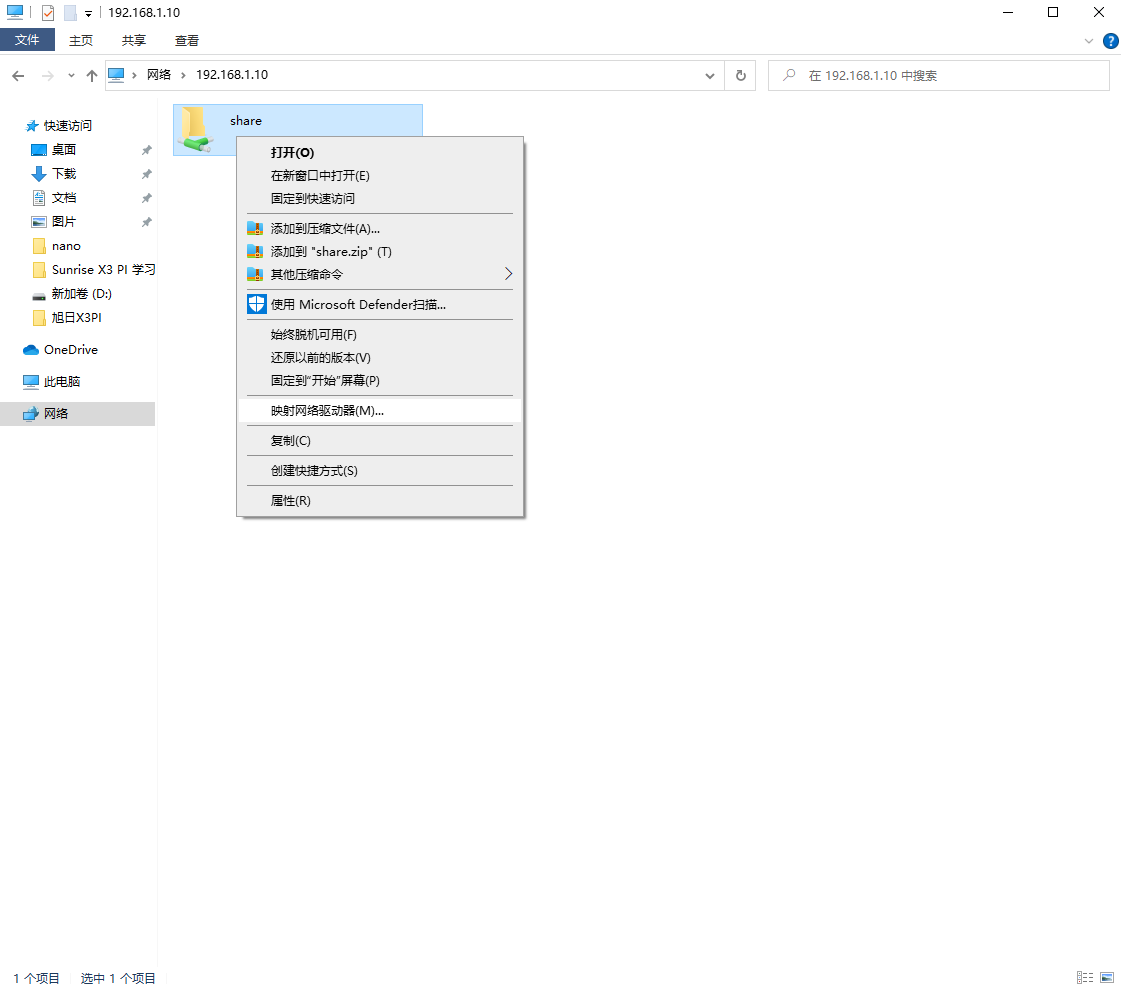
Enable Windows Samba Client
If the above method is not feasible, try the following method:
In Win10, open Control Panel -> Programs -> Turn Windows features on or off -> Open SMB client, restart to take effect.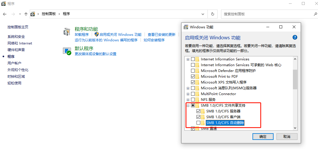
Official Resources
Softwares
Demo
FAQ
Support
Monday-Friday (9:30-6:30) Saturday (9:30-5:30)
Email: services01@spotpear.com
[Tutorial Navigation]
- Introduction
- System Installation
- System Configuration
- System Update
- Cable and Network Configuration
- Wireless Network Configuration
- DNS Service
- CPU Frequency Scaling Strategy
- Bluetooth
- File Transfer
- Official Resources
- Softwares
- Demo
- FAQ
- Support