


- sales/support
Google Chat:---
- sales
+86-0755-88291180
- sales01
sales@spotpear.com
- sales02
dragon_manager@163.com
- support
tech-support@spotpear.com
- CEO-Complaints
zhoujie@spotpear.com
- Only Tech-Support
WhatsApp:13246739196
- Purchase/Shipping/Refund
WhatsApp:13424403025
Write Image for Compute Module Boards eMMC version
EMMC version cannot use SD card for booting, please note it
1. Download the newest Raspberry Pi image from Raspberry Pi Website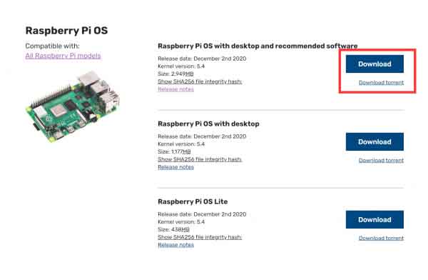
If the memory of the eMMC of your board is small, we will recommend you to download the second version or the Lite version of the Raspberry Pi image.
2. Download and open the software rpiboot software with administrator authority to install the driver and start the tool. After the installation is successful, there is an application of rpiboot.exe in the installation directory.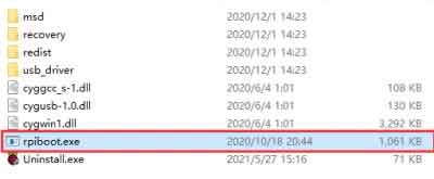
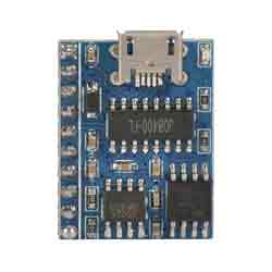
3. Connect BOOT and GND, set the switch to ON, or just connect the USB C port. You can check the product page to understand the location of the BOOT pin, for example: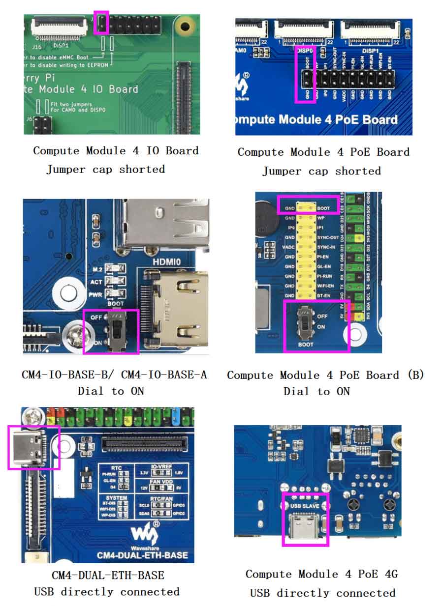
4. Connect the Micro USB/Type C interface(SLAVE port) of carrier board to host PC, then connect a power adapter to the cattier board.
If you use the following products, you do not need to connect the power adapter:
CM4-IO-BASE-B
CM4-IO-BASE-A
Compute Module 4 PoE Board (B)
5.After connecting, the boards should be recognized as BCMxxx devices in Windows PC.
Run the rpiboot.exe as administrator(The software in the installation directory of Step 2).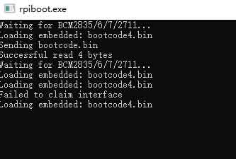
Then the boards will be recognized as a portable disk, just format and write it with a new image.
Note: If your PC didn't recognize the BCMxxx device, please check connection again. Note that the USB cable used should be an OTG cable. If you cannot write the image successfully, please try:
- Use Windows10 PC instead of Windows 7 or Linux. The other two OS are unstable as feedback.
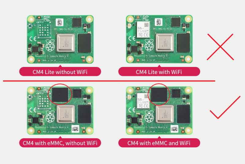
- Check if you write the eMMC version but not the Lite version. The eMMC version has one more chip than the Lite version.
- Connect a power adapter to the Power interface.
- Change to another USB OTG cable
- Change to another USB port of PC。
- Try to restart your host PC
- Remount the CM4 board and try it again.
- Try with another PC.
6. Format the CM4 (the portable disk) by SDFormatter.exe software
7. Write the Raspberry Pi image to the CM4 by Win32DiskImager.exe software, Choose the image file and click "Write" to start. It may prompt to format the CM4 again after writing, just ignore it.
8. After writing, a disk named BOOT is recognized, go into the disk and modify the config.txt file. Add the line to the file: dtoverlay=dwc2,dr_mode=host
9. To finish, eject the BOOT disk from the host PC. Disconnect the USB cable and power adapter, disconnect the BOOT, and set the switch into OFF. restart the board and go ahead with the examples.