- sales/support
Google Chat:---
- sales
+86-0755-88291180
- sales01
sales@spotpear.com
- sales02
dragon_manager@163.com
- support
tech-support@spotpear.com
- CEO-Complaints
zhoujie@spotpear.com
- Only Tech-Support
WhatsApp:13246739196
- Purchase/Shipping/Refund
WhatsApp:13424403025
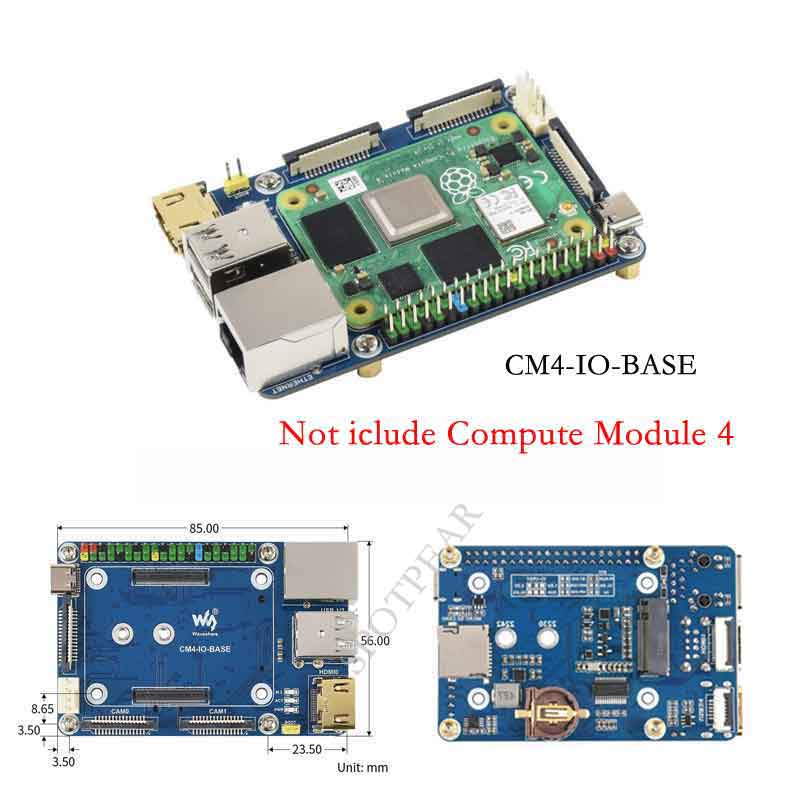
Raspberry Pi CM4-IO-BASE-B User Guide
Overview
This is an IO board for evaluating the Raspberry Pi CM4 or being integrated into end products. the board feature PoE function, it can be used for all variants of CM4.
Precautions for use
1: FAN fans only support 5V fans. 12V is not supported. Confirm the fan voltage before connecting.
2: The DSI display interface is the DSI0 interface, and the DSI1 display interface is not connected.
3: Type C interface can be used for power supply or USB SLAVE interface for burning image.
4: In order to ensure the normal power supply of CM4, please do not connect other devices when using the Type C interface to burn the image.
5: When CM4 is in normal use, it needs to provide 5V 2A power supply for CM4. Otherwise, problems such as automatic shutdown, frequency reduction, etc. may occur.
6: When using the M.2 interface, please use the matching screws. Using screws of other lengths may cause the CM4 core to be damaged by the screws.
7: The module does not have any protection, please do not short-circuit the power supply.
Dimension
CM4-IO-BASE-B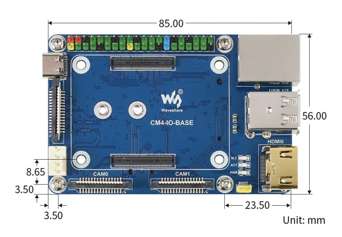
Compute_Module 4 Core board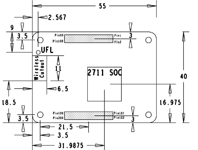
What's on board
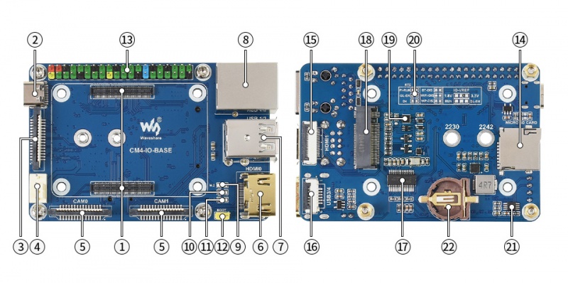
| No. | Component | Description | |
| 1 | CM4 connector | Suitable for all variants of Compute Module 4 | |
| 2 | DC power supply/programming interface | 5V/2.5A power supply, also can be used as eMMC programming interface | |
| 3 | DISP Interface | MIPI DSI Display interface | |
| 4 | FAN Interface | Convenient access to the cooling fan, support speed regulation and speed measurement | |
| 5 | CAM Interface | Dual MIPI CSI camera interface | |
| 6 | HDMI0 Interface | HDMI Interface,Support 4K 30fps output | |
| 7 | USB 2.0 Interface | 2-channel USB 2.0 Interface, support various USB device insertion | |
| 8 | Gigabit Ethernet | RJ45 Gigabit Ethernet port, support 10/100 / 1000M network access | |
| 9 | M.2 indicators | Indicates the working status of the interface | |
| 10 | ACT indicators | Raspberry Pi operating statusindicator | |
| 11 | PWR indicators | Raspberry Pi power indicator | |
| 12 | BOOT | Jumper cap connection:CM4 USB Type C Boot Jumper cap is not connected: eMMC and SD card Boot | |
| 13 | 40PIN GPIO Interface | Conveniently connect various HAT modules | |
| 14 | Micro SD Card interface | Used to connect to the Micro SD card with system, only for Lite version | |
| 15 | HDMI1 interface | HDMI1 Interface,Support 4K 30fps output | |
| 16 | USB 2.0 interface | USB 2.0 Cable interface, connected through the adapter board | |
| 17 | FE1.1S | USB HUB chip, USB Interface 1 expand 4 | |
| 18 | M.2 Interface | Suitable for NVIE solid state drives, or communication modules that support PCIE M.2 interface | |
| 19 | RTC | Support RTC wake up, shutdown, restart, or other functions | |
| 20 | RTC interrupt pin switch | PI-RUN: RTC trigger interrupt CM4 restart GN-EN: RTC trigger interrupt CM4 shutdown D4: RTC trigger interrupt D4 pin trigger | |
| 21 | EMC2301 | Fan controller, control fan speed, measure fan speed | |
| 22 | RTC Battery connector | Can be connected to CR1220 button battery |