- sales/support
Google Chat:---
- sales
+86-0755-88291180
- sales01
sales@spotpear.com
- sales02
dragon_manager@163.com
- support
tech-support@spotpear.com
- CEO-Complaints
zhoujie@spotpear.com
- sales/support
WhatsApp:13246739196
Raspberry Pi 2.8inch DPI LCD User Guide
Introduction
480 x 640, 2.8inch IPS Display for Raspberry Pi, DPI interface, 5-points capacitive touch control.
Features
- 2.8 inch IPS Display, 480 x 640 hardware resolution.
- Designed for Raspberry Pi, based on Raspberry Pi 40pin GPIO interface.
- Using the DPI666 interface of Raspberry Pi to drive LCD, refresh rate up to 60Hz.
- Drive capacitive touch through the I2C interface of Raspberry Pi, 5-point touch, toughened glass panel, hardness up to 6H.
- Supports Raspberry Pi OS and Kali systems.
How to use
Hardware connection
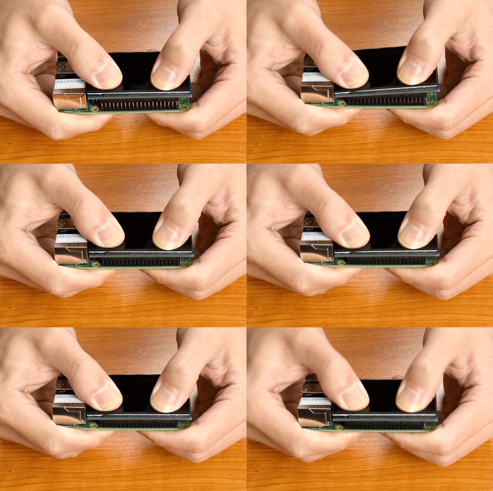
Please follow the steps below to slowly install the DPI LCD to the 40PIN GPIO interface of the Raspberry Pi.
Software setting
If you don't know the difference between the two branches of Raspberry Pi OS, you can check the following introduction #Introducing the Raspberry Pi OS fork
For Raspberry Pi OS Bookworm and Bullseye branch
Please download the latest version of the image from the Raspberry Pi official website. 1. Download the compressed file to the PC, and extract the img file.
2. Connect the TF card to the PC and use SDFormatter to format the TF card.
3. Open the Win32DiskImager software, select the system image prepared in step 1, and click write to burn the system image.
4. After the programming is completed, open the config.txt file in the root directory of the TF card, add the following code at the end of config.txt, and save it
dtoverlay=vc4-kms-v3d
dtoverlay=waveshare-28dpi-3b-4b
dtoverlay=waveshare-28dpi-3b
dtoverlay=waveshare-28dpi-4b
dtoverlay=waveshare-touch-28dpi
dtoverlay=vc4-kms-dpi-2inch8
5. Download the 2.8inch DPI LCD DTBO file and extract the dtbo files. Copy these files to the overlays directory (/boot/overlays/).
6. Insert the TF card into the Raspberry Pi, power on the Raspberry Pi, and wait for more than 30 seconds to display normally.
For Raspberry Pi OS Buster branch and Ubuntu system
1. Open the config.txt file in the root directory of the TF card, add the following code at the end of config.txt, save, and safely eject the TF card.
gpio=0-9=a2
gpio=12-17=a2
gpio=20-25=a2
dtoverlay=dpi24
enable_dpi_lcd=1
display_default_lcd=1
extra_transpose_buffer=2
dpi_group=2
dpi_mode=87
dpi_output_format=0x7F216
hdmi_timings=480 0 26 16 10 640 0 25 10 15 0 0 0 60 0 32000000 1
dtoverlay=waveshare-28dpi-3b-4b
dtoverlay=waveshare-28dpi-3b
dtoverlay=waveshare-28dpi-4b
Note: If it is Raspberry Pi 4, also need to comment out dtoverlay=vc4-fkms-V3D.
2. Download the 2.8inch DPI LCD DTBO file and extract the dtbo files. Copy these files to the overlays directory (/boot/overlays/).
3. Save and quit the TF card safely, and insert the TF card into the Raspberry Pi.
4. Insert the 2.8-inch DPI LCD into the 40PIN GPIO interface of the Raspberry Pi, power on the Raspberry Pi, and wait for about 30 seconds to display normally.
Introducing the Raspberry Pi OS Branch
On December 2, 2021, the Raspberry Pi OS for Raspberry Pi split into two branches, the Buster branch, and the Bullseye branch.
The Buster branch is a continuation of the old system, which is more stable and uses Raspicam as the default camera subsystem.
The Bullseye branch adds some new features, including KMS as the default display driver and lib-camera as the default camera subsystem.
Image download address
More detailed information can be found at:
Notes: the above information was updated on January 24, 2022. Due to the frequent update of the Raspberry Pi image, when you see this information, the relevant information may be out of date. The actual performance of the image shall prevail. This is for reference only.
Rotation (Working with Raspberry Pi)
Raspberry Pi OS and Kali display rotation
First, check whether the KMS or FKMS driver is loaded on the system you are using.
Check method: In /boot/config.txt, check whether the line dtoverlay=vc4-kms-v3d or dtoverlay=vc4-fkms-v3d is turned on.
With KMS or FKMS driver loaded
Use the following command for display rotation:
sudo nano /etc/xdg/lxsession/LXDE-pi/autostart
#Enter the command corresponding to the display rotation angle at the end of the autostart file, and it will take effect after rebooting the system. Only available on desktop version systems
#0: rotate 0 degrees; 1: rotate 270 degrees; 2: rotate 180 degrees; 3: rotate 90 degrees
xrandr -o 1
No KMS or FKMS driver loaded
Use the following command for display rotation:
sudo nano /boot/config.txt
#Enter the command corresponding to the display rotation angle at the end of the config.txt file, and it will take effect after rebooting the system.
#0: rotate 0 degrees; 1: rotate 90 degrees; 2: rotate 180 degrees; 3: rotate 270 degrees
display_rotate=3
Touch to Rotate
After the display is rotated, the position of the touch is incorrect because the touch doesn't change with the display angle. So the touch also needs to be modified.
1. Install libinput.
sudo apt-get install xserver-xorg-input-libinput
If the system you installed is Ubuntu or Jetson Nano. The installation code is:
sudo apt install xserver-xorg-input-synaptics
2. Create the xorg.conf.d directory under /etc/X11/ (if the directory already exists, proceed directly to step 3).
sudo mkdir /etc/X11/xorg.conf.d
3. Copy the 40-libinput-conf file to the directory you created just now.
sudo cp /usr/share/X11/xorg.conf.d/40-libinput.conf /etc/X11/xorg.conf.d/
4. Edit this file.
sudo nano /etc/X11/xorg.conf.d/40-libinput.conf
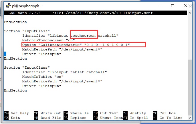
Find the part of the touchscreen, add the following statement inside, and then save the file.
Option "CalibrationMatrix" "0 1 0 -1 0 1 0 0 1"
Similar to the picture below:

5. Save and reboot your Pi.
sudo reboot
After completing these steps. The LCD could rotate 90 degrees for both display and touch functions.
Note:
90 degrees: Option "CalibrationMatrix" "0 1 0 -1 0 1 0 0 1"
180 degrees: Option "CalibrationMatrix" "-1 0 1 0 -1 1 0 0 1"
270 degrees: Option "CalibrationMatrix" "0 -1 1 1 0 0 0 0 1"
Others
Disable power saving
If you want to keep the display turning on all the time, you can disable the power-saving function.
Modify file lightdm.conf
sudo nano /etc/lightdm/lightdm.conf
Find the [SeatDefaults] option and uncomment the line"xserver-command", modify it as below:
#xserver-command=X
Modify this code to
xserver-command=X -s 0 -dpms
- -s # –Disable the display protection.
- dpms Disable power saving.
Reboot
sudo reboot
Control brightness by PWM
If you use Pi4, you need to update wiringPi first:
wget https://project-downloads.drogon.net/wiringpi-latest.deb
sudo dpkg -i wiringpi-latest.deb
gpio -v
# Check if it is 2.52 version
Control the brightness by PWM.
gpio -g mode 18 pwm      #Configure the PWM pin
gpio pwmc 100
gpio -g pwm 18 1023      #Set it as the brightest
gpio -g pwm 18 850       #(For Pi4, 850 is darkest; for Pi3, 680 is darkest)
gpio -g mode 18 out      #Free the pin and set it as output
Turn on/off the LCD
You can turn on/off the LCD with the following command.
Note: The command can only work when the PWM pin is free and in output mode.
sudo echo 1 | sudo tee /sys/class/backlight/rpi_backlight/bl_power
sudo echo 0 | sudo tee /sys/class/backlight/rpi_backlight/bl_power
Interface
- The pin of "NC" means that the touch screen does not occupy this pin, and the user can use it for other applications.
| PIN NO. | SYMBOL | DESCRIPTION |
|---|---|---|
| 1 | NC | Not connected |
| 2 | 5V | 5V power |
| 3 | VSYNC | Vertical synchronization |
| 4 | 5V | 5V power |
| 5 | HSYNC | Horizontal synchronization |
| 6 | GND | Ground |
| 7 | B2 | RGB signal lines |
| 8 | G4 | RGB signal lines |
| 9 | GND | Ground |
| 10 | G5 | RGB signal lines |
| 11 | G7 | RGB signal lines |
| 12 | PWM | Backlight control (Pi4 can only turn on/off the backlight. Only the earlier versions support brightness adjustment with PWM) |
| 13 | TP_INT | Interrupt pin of touch panel |
| 14 | GND | Ground |
| 15 | R4 | RGB signal lines |
| 16 | R5 | RGB signal lines |
| 17 | NC | Not connected |
| 18 | R6 | RGB signal lines |
| 19 | TP_SDA | The I2C SDA of touch panel |
| 20 | GND | Ground |
| 21 | B7 | RGB signal lines |
| 22 | R7 | RGB signal lines |
| 23 | TP_SCL | The I2C SCL of touch panel |
| 24 | B6 | RGB signal lines |
| 25 | GND | Ground |
| 26 | B5 | RGB signal lines |
| 27 | LCD_CLK | Clock pin of LCD panel |
| 28 | DE | Data enable of LCD panel |
| 29 | B3 | RGB signal lines |
| 30 | GND | Ground |
| 31 | B4 | RGB signal lines |
| 32 | G2 | RGB signal lines |
| 33 | G3 | RGB signal lines |
| 34 | GND | Ground |
| 35 | NC | Not connected |
| 36 | G6 | RGB signal lines |
| 37 | NC | Not connected |
| 38 | R2 | RGB signal lines |
| 39 | GND | Ground |
| 40 | R3 | RGB signal lines |
Raspberry Pi Long-press Right-click Settings
Test environment: 2022-04-04-raspios-bullseye-armhf 32-bit system
Supported models: Support Waveshare DSI LCD, DPI LCD, and HDMI LCD capacitive touch screen series.
Software Installation
wget https://files.waveshare.com/upload/1/18/Evdev-right-click-emulation.zip
unzip Evdev-right-click-emulation.zip
cd evdev-right-click-emulation
sudo apt install build-essential libevdev2 libevdev-dev
cd 'evdev-right-click-emulation'
sudo cp 'out/evdev-rce' '/usr/local/bin/'
sudo chmod +x '/usr/local/bin/evdev-rce'
Enter the command:
sudo evdev-rce
After running, you can touch and long press to realize the right-click function.
Set IP
sudo usermod -G 'input' -a pi
echo 'uinput' | sudo tee -a /etc/modules
sudo nano  /etc/udev/rules.d/99-uinput.rules
Add in 99-uinput.rules file.
KERNEL=="uinput", MODE="0660", GROUP="input"
Save it and run it in the terminal.
sudo udevadm control --reload-rules
sudo udevadm trigger
Then reboot:
sudo reboot
Run after reboot (no sudo needed at this point).
evdev-rce
After running, you can touch and long press to realize the right-click function.
Set Startup
Enter the terminal:
sudo mkdir ~/.config/autostart
sudo nano ~/.config/autostart/right_click.desktop
Add the following in right_click.desktop.
[Desktop Entry]
Version=1.0
Type=Application
Name=evdev-rce
GenericName=Enable long-press-to-right-click gesture
Exec=env LONG_CLICK_INTERVAL=1000 LONG_CLICK_FUZZ=200  /usr/local/bin/evdev-rce
Terminal=true
StartupNotify=false

#If you want to modify the sensitivity, you can modify the size of the two parameters, LONG_CLICK_INTERVAL=1000 LONG_CLICK_FUZZ=200.
Resource
3D Drawing
Software
FAQ
Question: What is the power consumption of this screen?
5V 160mA
Question: I have it connected to a Raspberry Pi Zero 2W. Some gray pixels end up green for some reason. I have attached a file to demonstrate. The actual pixel values are gray, and the bitmap screenshots of them are gray as well. However, through the 2.8" display, they look green. Is there a way to fix this?
Please download this file to replace it in the /boot/overlay directory.


