- sales/support
Google Chat:---
- sales
+86-0755-88291180
- sales01
sales@spotpear.com
- sales02
dragon_manager@163.com
- support
tech-support@spotpear.com
- CEO-Complaints
zhoujie@spotpear.com
- Only Tech-Support
WhatsApp:13246739196
- Purchase/Shipping/Refund
WhatsApp:13424403025
Raspberry Pi Camera IR CUT -175° User Guide
1. Basic operations
1) Please download Raspbian OS from http://www.raspberrypi.org/
2) Format your TF card with the SDFormatter.exe.
Notices: The capability of TF card in used here should be more than 4GB. In this operation, a TF card reader is also required, which has to be purchased separately.
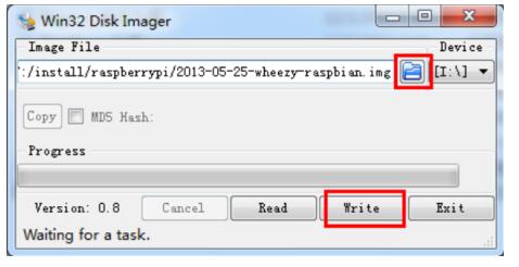
3) Start the Win32DiskImager.exe, and select the system image file copied into your PC, then, click the button Write to program the system image file.
Figure 1: Programming the system image file with Win32DiskImager.exe
2. Camera module setup
2.1. CONNECTING THE CAMERA The flex cable inserts into the connector situated between the Ethernet and HDMI ports, with the silver connectors facing the HDMI port.
The flex cable connector should be opened by pulling the tabs on the top of the connector upwards then towards the Ethernet port.
The flex cable should be inserted firmly into the connector, with care taken not to bend the flex at too acute an angle.
The top part of the connector should then be pushed towards the HDMI connector and down, while the flex cable is held in place.
2.2. ENABLING THE CAMERA
1) Update and upgrade Raspbian from the Terminal:
apt-get update
apt-get upgrade
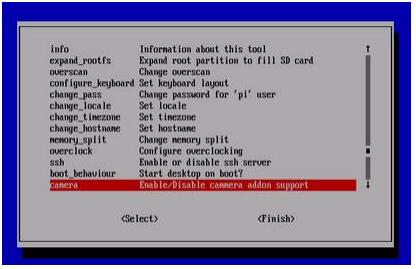
2) Open the raspi-config tool from the Terminal:
sudo raspi-config
3) Select Enable camera and hit Enter, then go to Finish and you'll be prompted to reboot
Figure 2: Enable camera
2.3. USING THE CAMERA
Power up and take photos or shoot videos from the Terminal:
1) Taking photos:
raspistill -o image.jpg
2) Shooting videos:
raspivid -o video.h264 -t 10000 -t 10000
means the video last 10s, changeable.
3. Reference
Libraries for using the camera are available in:
More information:
http://www.raspberrypi.org/camera
https://www.raspberrypi.org/archives/tag/camera-board