




- sales/support
Google Chat:---
- sales
+86-0755-88291180
- sales01
sales@spotpear.com
- sales02
dragon_manager@163.com
- support
tech-support@spotpear.com
- CEO-Complaints
zhoujie@spotpear.com
- Only Tech-Support
WhatsApp:13246739196
- Purchase/Shipping/Refund
WhatsApp:13424403025
- HOME
- >
- ARTICLES
- >
- Common Moudle
- >
- Sensors
TOF MINI Range Sensor User Guide
Features
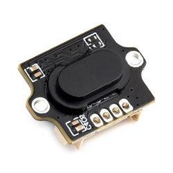
This laser ranging module is based on a D-TOF single-point laser sensor, with a built-in MCU and housed in a compact enclosure. It supports sunlight rejection and dirt compensation algorithms to measure target distance. With optical collimation design, it can measure distances to various targets under ambient light up to 20K Lux.
Disclaimer
The TOF MINI Range Sensor series is not authorized for use in critical applications where failure could impact personal safety (e.g., life support). In such applications, failure of the TOF MINI Range Sensor series could cause severe personal injury or death. Customers who use or sell the TOF MINI Range Sensor series in such safety-critical applications do so at their own risk and agree to fully indemnify Waveshare and its representatives against any damages arising from such use.
The TOF MINI Range Sensor series provided by Waveshare has obtained EU laser product certification. Before using or selling these products, verify whether these certifications apply in your region. Products incorporating the TOF MINI Range Sensor series must obtain approval from the relevant authorities in accordance with local laser product regulations before being sold in that region.
Applications
- Distance detection for smart devices
- Robot obstacle avoidance
- Drone altitude measurement
- Liquid level detection
- Industrial automation ranging
Working Principle
TOF is an absolute distance detection technology. The sensor emits modulated near-infrared light, which reflects off objects. The sensor calculates the time difference or phase difference between emission and reflection, converts it into target distance, and generates depth information. TOF is commonly used in people proximity detection, robot obstacle avoidance, camera autofocus, and similar scenarios.
Specifications
| Parameter | Specification |
|---|---|
| Model | TOF MINI Range Sensor |
| Typical ranging range | 0.02 m - 4 m |
| Accuracy | ± (1% - 3%) |
| Field of view | 25° - 30° |
| Refresh rate | 30 Hz (Batch customization supported, maximum up to 90 Hz) |
| Ambient light immunity | 20K Lux |
| Operating temperature | -20℃ - +70℃ |
| Operating humidity | 35% - 80%RH |
| Laser safety class | LASER CLASS 1 (IEC 60825-1: 2014) |
| Wavelength | 940 nm |
| Communication interface | UART |
| Baud rate | 115200 |
| Data Bits | 8 |
| Stop Bits | 1 |
| Parity | NONE |
| Supply voltage | 4 V - 5.6 V |
| Power consumption | 100 mW - 140 mW |
| Average current / Peak current | 25 mA / 26 mA |
| Product weight | 3 g |
| Housing material | PC |
| Storage temperature | -40℃ - +80℃ |
| Product dimensions | 17.37 × 13.00 × 6.88 (mm) |
- The sensor's IO level is 3.3 V. If using 5 V IO levels, a level shifter is required; otherwise, the sensor may be damaged.
Pinout
| Pin | Label | Description |
|---|---|---|
| 1 | VCC | 5 V power positive |
| 2 | RXD | UART input |
| 3 | TXD | UART output |
| 4 | GND | Power ground |
Protocol Analysis
Click to expand
Quick Test
Use the test software Serial Debug Assistant together with the USB TO TTL (B) for quick viewing of serial output.
Test Preparation
- Windows computer
- USB TO TTL (B) 1 PCS
- TOF MINI Range Sensor 1 PCS
- Matching cables
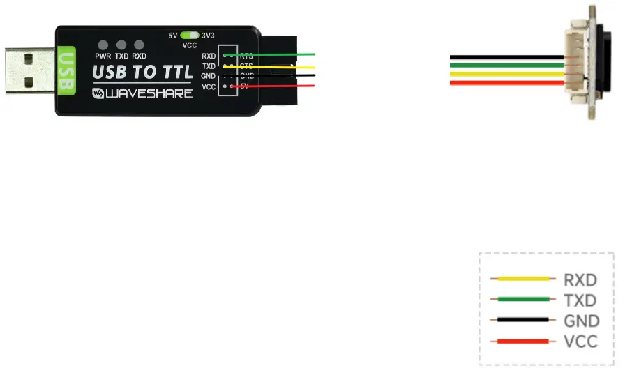
Hardware Connection
Connect as shown in the figure below.
Start Testing
- Connect the USB TO TTL (B) to the computer's USB port.
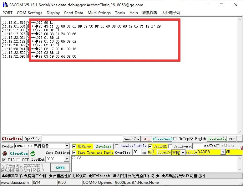
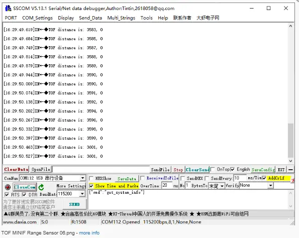
- Open the serial debug assistant (SSCOM), select the corresponding COM port, set baud rate to 115200, data bits to 8, stop bits to 1, and parity to NONE.
- Open the serial port to view the distance data output by the sensor.
- Connect the USB TO TTL (B) to the computer's USB port.
①Send query command
②Obtain real-time data
Working with Raspberry Pi
This chapter includes the following sections:
Setting Up the Development Environment
1. Installation and Configuration
- For Raspberry Pi system installation and usage instructions, please refer to the Raspberry Pi Documentation.
- After successful boot, configure the Raspberry Pi environment.
2. Downloading the Example
# Download the Example
wget https://files.waveshare.com/wiki/TOF-MINIF-Range-Sensor/TOF_MINIF_Range_Sensor_Demo.zip
unzip TOF_MINIF_Range_Sensor_Demo.zip
cd TOF_MINIF_Range_Sensor_Demo/
3. Enabling UART on Raspberry Pi
- Enter the command in the Raspberry Pi terminal:
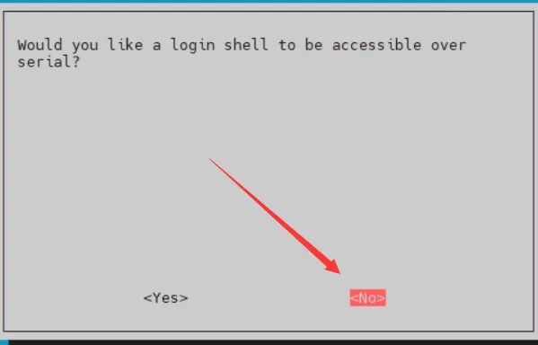
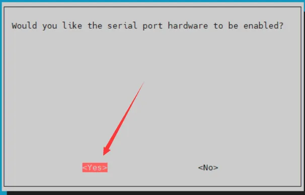
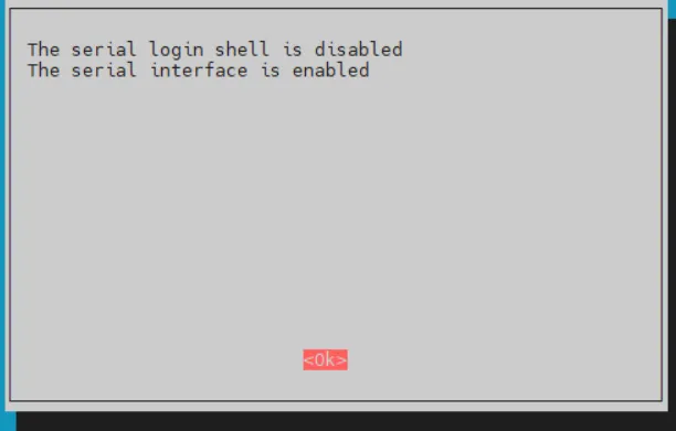
sudo raspi-config nonint do_serial 2. - In the pop-up window, select NO for the first option and YES for the second, then select OK.
Example
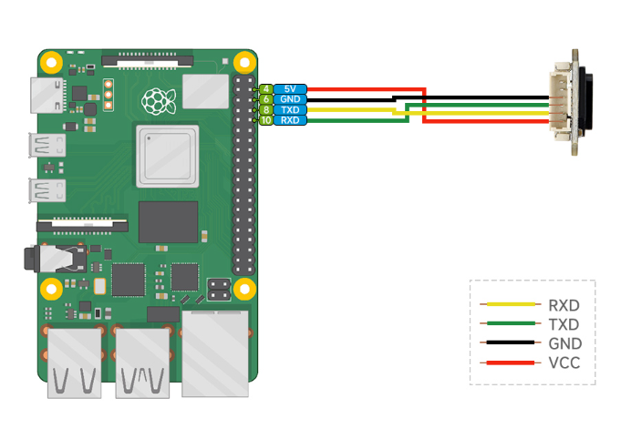
Hardware Connection
Connect as shown in the figure below.
Running the C Example
cd ~/TOF_MINIF_Range_Sensor_Demo/Raspberry/c/
make
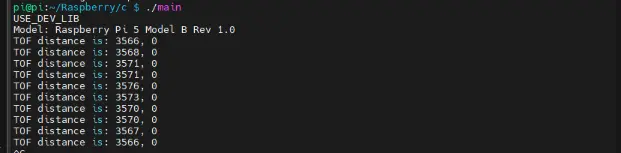
./main
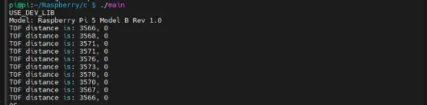
Below is the output of the C program:
Running the Python Example
cd ~/TOF_MINIF_Range_Sensor_Demo/Raspberry/python/example
python main.py
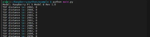
Below is the output of the Python program:
Working with ESP32-S3
This chapter includes the following sections:
Setting Up the Development Environment
1. Installation and Configuration
- For ESP32-S3 environment setup and basic usage, please refer to the following links:
- After setting up the environment, connect the sensor and download the example package.
Example
Hardware Connection
Connect as shown in the figure below.
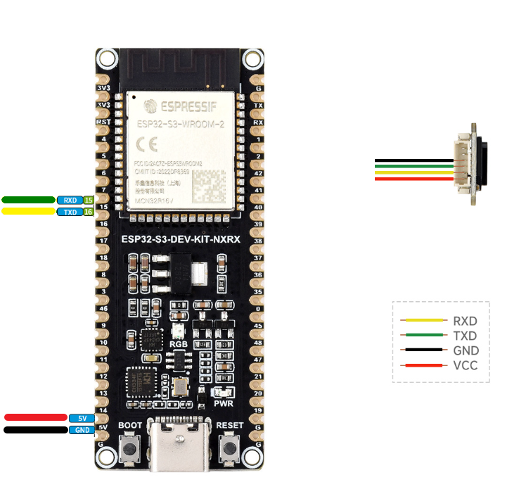
Running the Arduino ESP32 Example
Navigate to
TOF_MINIF_Range_Sensor_Demo/TOF_MINIF_Range_Sensor_Demo/ESP32S3/Arduino/TOF_UART_Demoand double-click theTOF_UART_Demo.inofile.Select the development board:
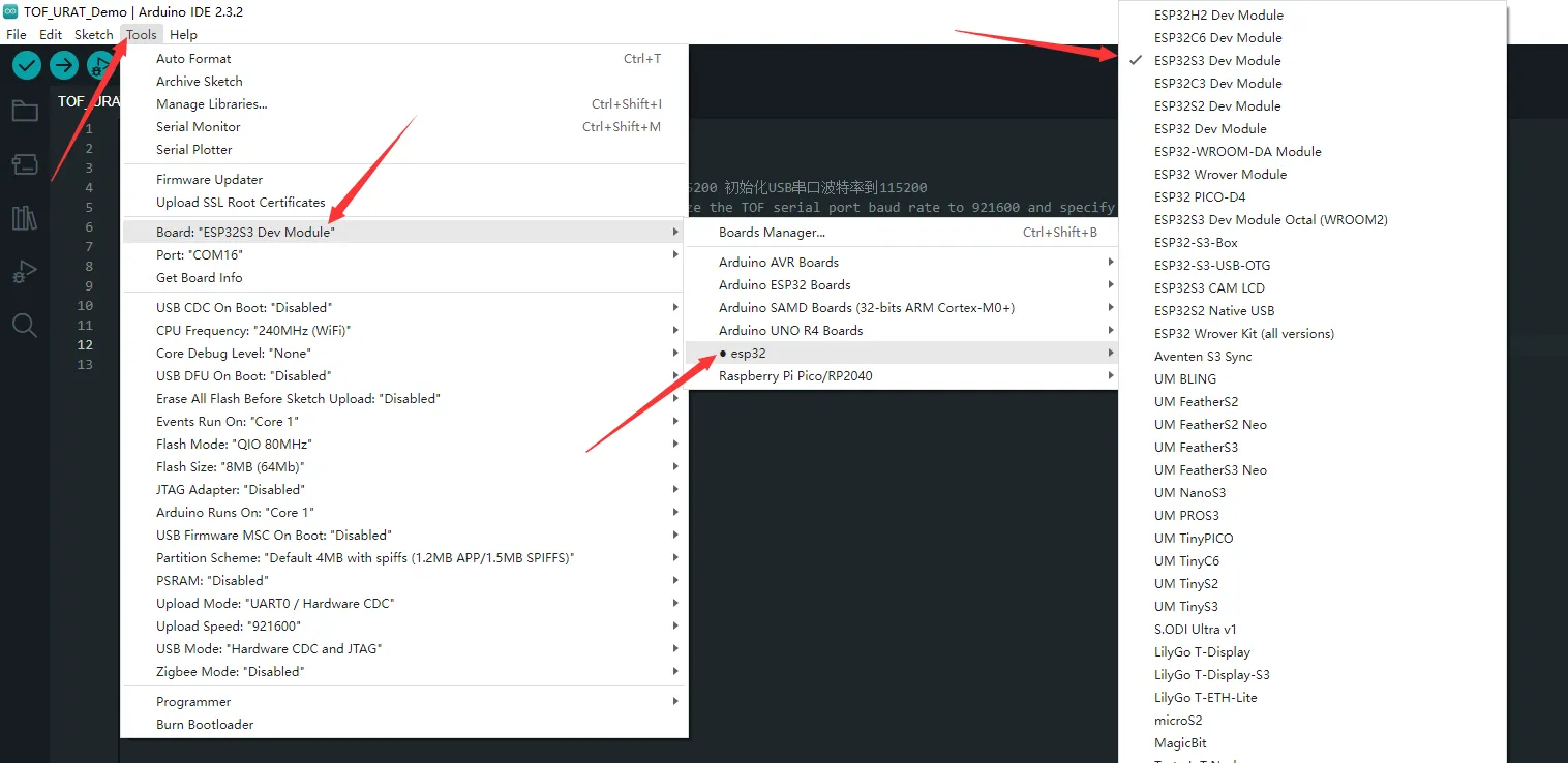
Select the ESP32-S3 port, then compile and upload.
After upload is complete, open the Serial Monitor to view the output.
Running the MicroPython Example
Navigate to
TOF_MINIF_Range_Sensor_Demo/TOF_MINIF_Range_Sensor_Demo/ESP32S3/pythonand double-click theTOF_UART_Demo.pyfile.Set the chip model to ESP32 and select the corresponding port:
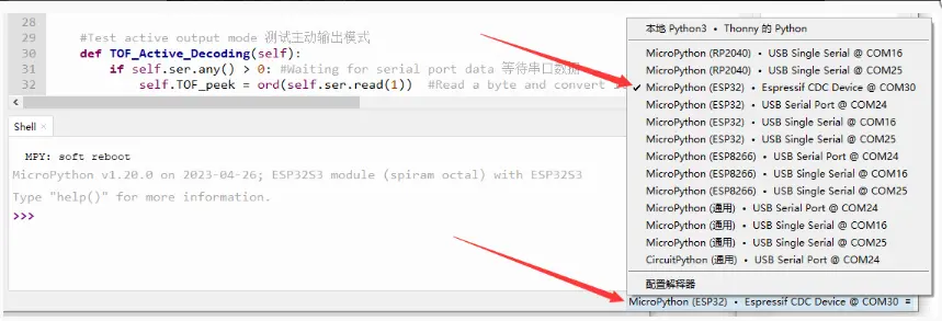
Select the ESP32-S3 port, then run the example.
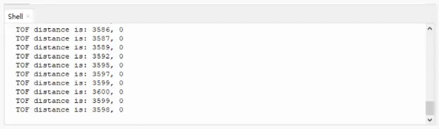
The shell will display the relevant output.
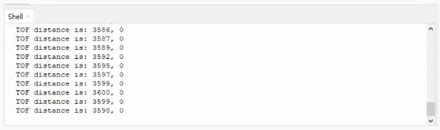
Working with Raspberry Pi Pico
This chapter includes the following sections:
Setting Up the Development Environment
1. Installation and Configuration
- For Raspberry Pi Pico environment setup and basic usage, please refer to the following links:
- After setting up the environment, connect the sensor and download the example package.
Example
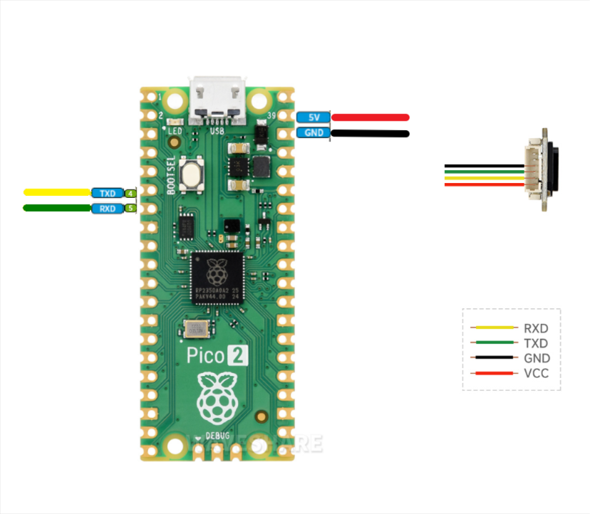
Hardware Connection
Connect as shown in the figure below.
Running the Arduino Pico Example
Navigate to
TOF_MINIF_Range_Sensor_Demo/TOF_MINIF_Range_Sensor_Demo/pico/Arduino/TOF_UART_Demoand double-clickTOF_UART_Demo.inoto open the project.Select the chip model and port.
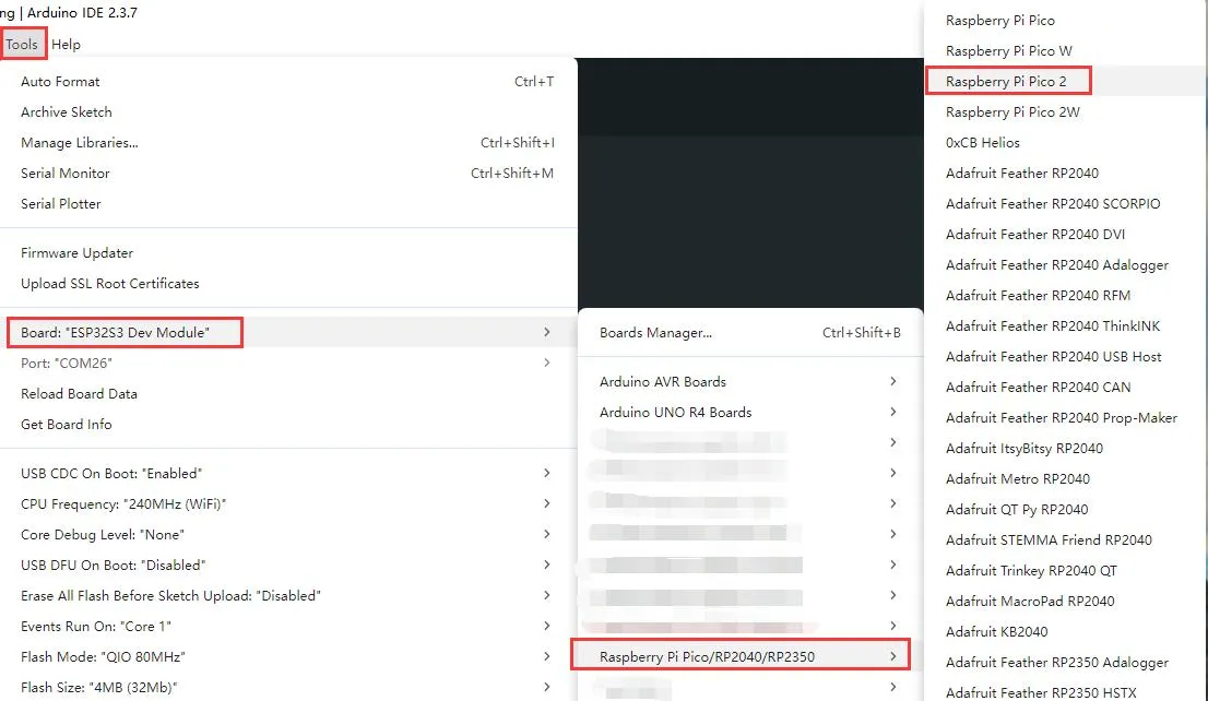
After upload is complete, open the Serial Monitor to view the output.
Running the MicroPython Example
First flash the MicroPython firmware to the Raspberry Pi Pico.
Navigate to
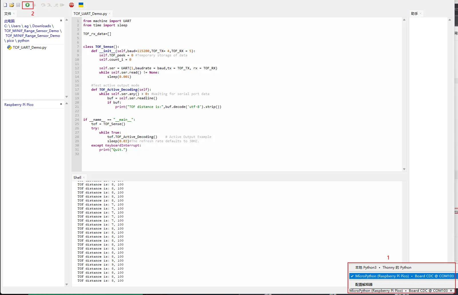
TOF_MINIF_Range_Sensor_Demo/TOF_MINIF_Range_Sensor_Demo/pico/pythonand double-clickTOF_UART_Demo.pyto open the project in Thonny.Select the development board.
Select the Raspberry Pi Pico port, then run the example.
The shell will display the relevant output.
Running the C Example
Navigate to
TOF_MINIF_Range_Sensor_Demo/Pico/cand open this folder in VS Code.Import this project in the Pico tools.
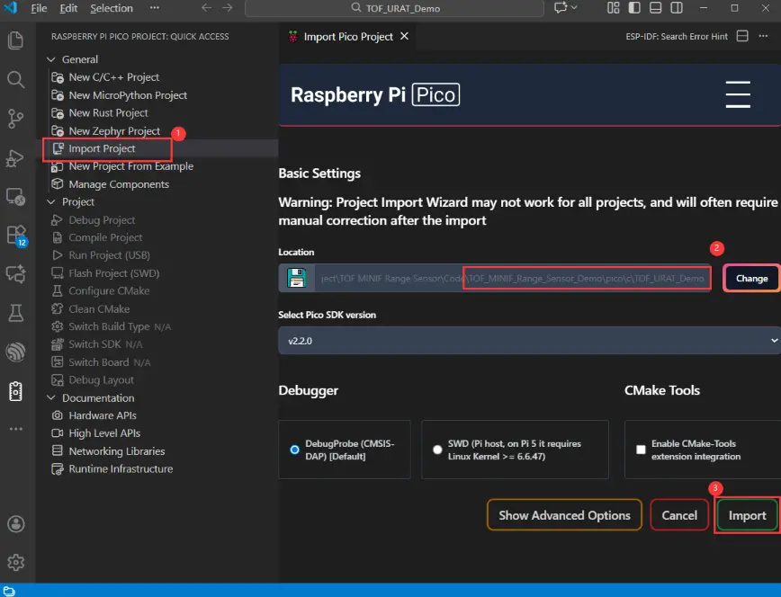
After import succeeds, click "Compile" to build. After compilation, put the Pico into BOOT mode and copy the UF2 firmware to the RP2040 disk.
Open a serial debug tool to view the output.
Working with Arduino
This chapter includes the following sections:
Setting Up the Development Environment
1. Installation and Configuration
- For setting up the Arduino environment and basic usage, please refer to this R4 link; R3 comes pre-installed by default.
- After setting up the environment, connect the sensor and download the example package.
2. Hardware Configuration
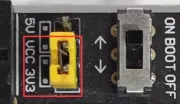
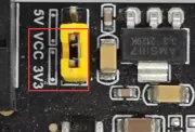
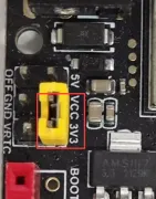
- The IO level of the Arduino board must be 3.3 V. If using 5 V IO levels, a level shifter is required; otherwise, the sensor may be damaged.
- When using Waveshare R3/R4, set the following jumpers to 3.3 V.
| Image | Description |
|---|---|
| Arduino UNO R3 |
| Arduino UNO R4 |
| Arduino UNO R4 WIFI |
Example
Hardware Connection
Connect as shown in the figure below.
| Image | Description |
|---|---|
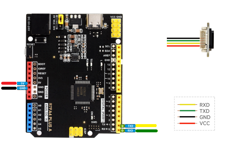 | Arduino UNO R3 |
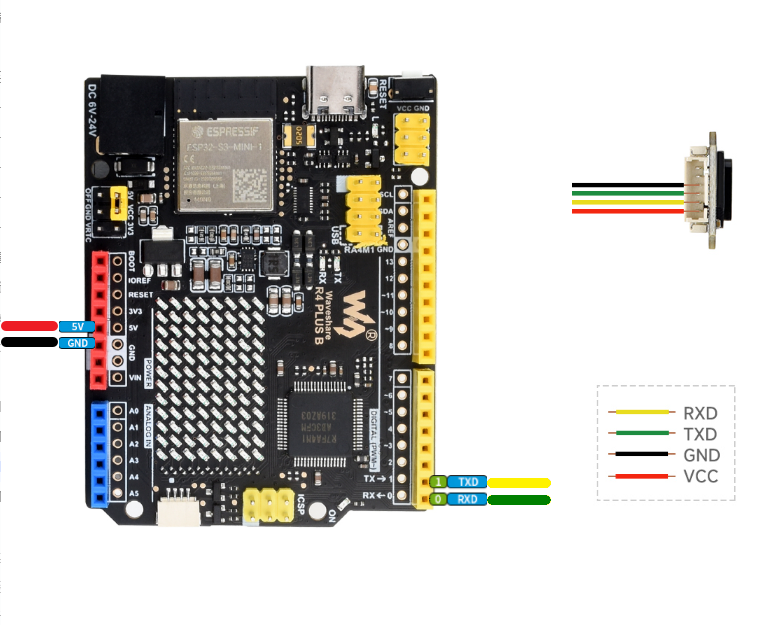 | Arduino UNO R4 |
Running the Example
Navigate to
TOF_MINIF_Range_Sensor_Demo/TOF_MINIF_Range_Sensor_Demo/Arduino/TOF_UART_Demoand double-click theTOF_UART_Demo.inofile.Select the development board:
Image Description 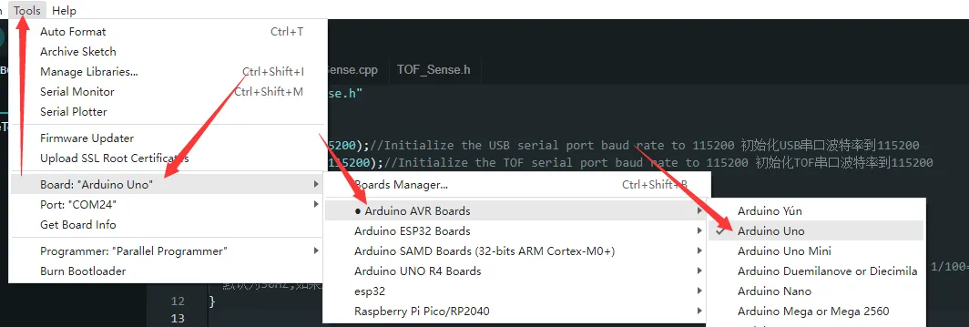
Arduino UNO R3 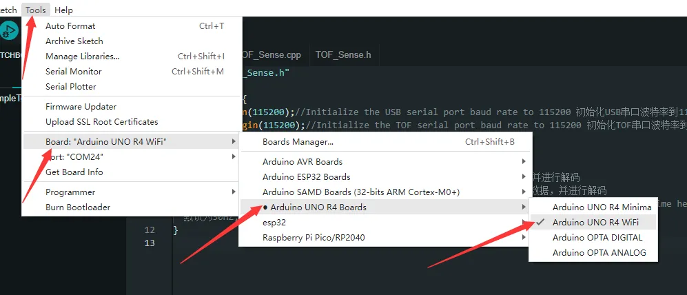
Arduino UNO R4 Select the board port, then compile and upload.
After upload is complete, open the Serial Monitor to view the output.
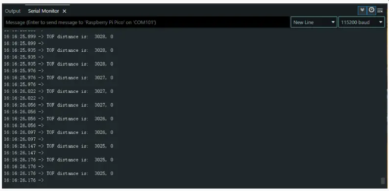
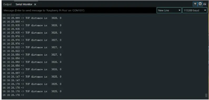
Example Showcase
Real-time distance data is output by default. To use other examples, set the corresponding example value to 1.
Arduino
MicroPython
Raspberry Pi
Support
Monday-Friday (9:30-6:30) Saturday (9:30-5:30)
Email: services01@spotpear.com
[Tutorial Navigation]
- Features
- Disclaimer
- Applications
- Working Principle
- Specifications
- Pinout
- Protocol Analysis
- Quick Test
- Working with Raspberry Pi
- Working with ESP32-S3
- Working with Raspberry Pi Pico
- Working with Arduino
- Example Showcase
- Support