- sales/support
Google Chat:---
- sales
+86-0755-88291180
- sales01
sales@spotpear.com
- sales02
dragon_manager@163.com
- support
tech-support@spotpear.com
- CEO-Complaints
zhoujie@spotpear.com
- Only Tech-Support
WhatsApp:13246739196
- Purchase/Shipping/Refund
WhatsApp:13424403025
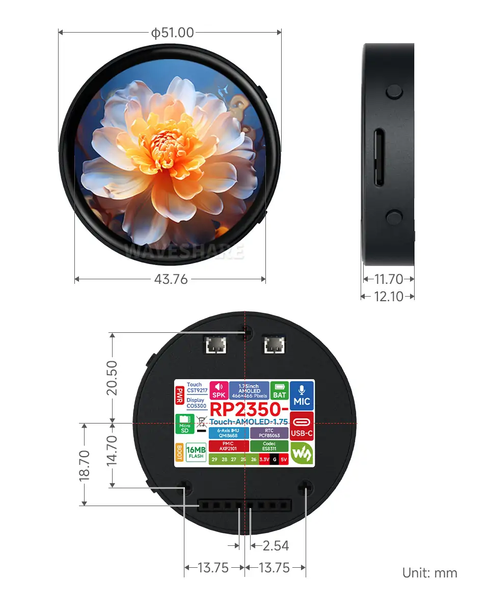
RP2350-Touch-AMOLED-1.75 User Guide
Features
- Utilizes the RP2350A microcontroller chip designed by Raspberry Pi
- Unique dual-core, dual-architecture, featuring dual-core ARM Cortex-M33 processors and dual-core Hazard3 RISC-V processors, both operating at up to 150MHz, allowing flexible switching between the two architectures for users
- Built-in 520KB of SRAM and 16MB of on-chip Flash, with a reserved PSRAM pad
- Utilizes a Type-C port, eliminating concerns about plug orientation.
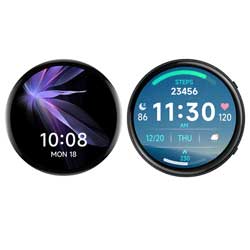
- Onboard 1.75inch capacitive touch high-definition AMOLED screen, 466 × 466 resolution, 65K colors, capable of clearly displaying color images
- Built-in CO5300 driver chip and CST9217 capacitive touch controller chip, communicating via QSPI and I2C interfaces respectively, minimizing the use of I/O pin resources
- Onboard 3.7V MX1.25 lithium battery charge/discharge interface, beneficial for mobile scenarios
- USB1.1 host and slave device support
- Supports low-power sleep and hibernation modes
- Drag-and-drop programming using mass storage over USB
- 5 × multi-functional GPIO pins
- 1 × SPI, 2 × I2C, 2 × UART, 4 × 12-bit ADCs and 5 × controllable PWM channels
- Accurate on-chip clock and timer
- Built-in temperature sensor for real-time chip temperature monitoring
- 12 × programmable I/O (PIO) state machines for custom peripheral support
Onboard Resources
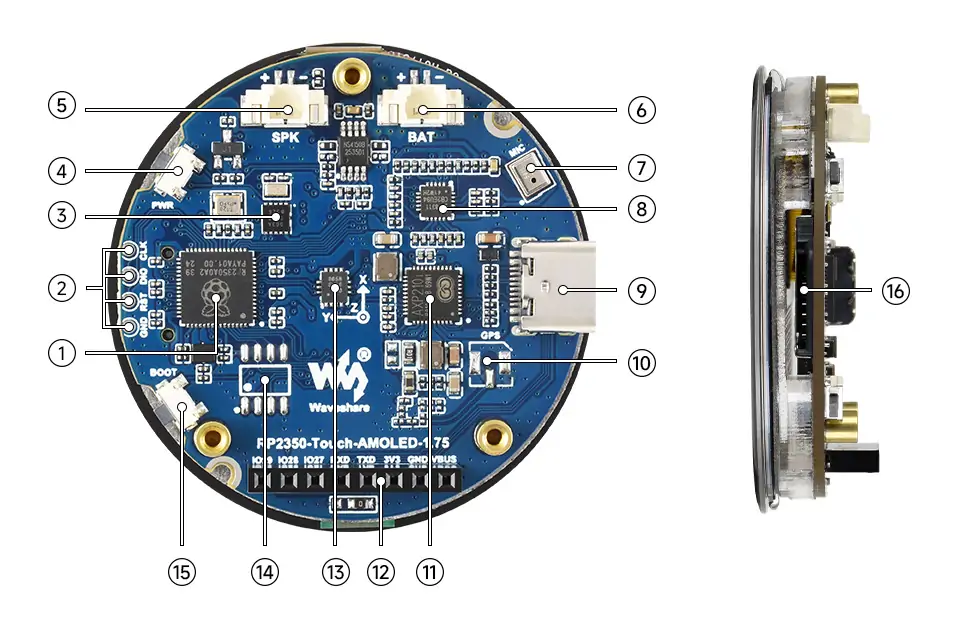
- RP2350A Dual-core, dual-architecture processor, up to 150MHz operating frequency
- Debug Interface Convenient for program downloading and online debugging
- PCF85063 RTC clock chip
- PWR Power Button Controls power on/off and supports custom functions
- MX1.25 2P Speaker Interface MX1.25 2P connector, can be used to connect a speaker
- MX1.25 Lithium Battery Interface Can be used to connect a 3.7V lithium battery, supports charging/discharging and adjustable charging current
- Microphone For audio capture
- ES8311 Low-power audio codec IC
- Type-C Interface For program downloading, supports USB 1.1 host and slave device modes
- IPEX Gen 1 GPS antenna holder GPS version includes built-in LC76G module, external GNSS ceramic antenna
- AXP2101 Highly integrated power management chip
- 2.54mm Pitch 8PIN Header Convenient for external debugging or connecting sensors
- QMI8658 6-axis IMU includes a 3-axis gyroscope and a 3-axis accelerometer
- PSRAM Interface Compatible with mainstream PSRAM chips, for user expansion/upgrade
- BOOT Button Press during reset to enter download mode
- TF Card Slot Supports TF card for expanded storage
Interfaces
Dimensions
Without Case
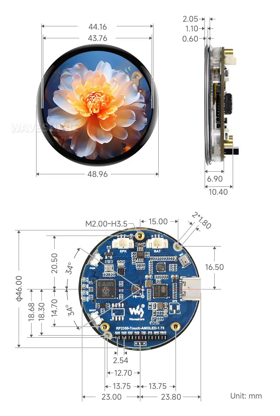
With Case
Development Methods
The RP2350-Touch-AMOLED-1.75 supports three programming languages: MicroPython, C/C++, and Arduino, offering developers flexible choices. You can select the appropriate development tools and programming methods based on your project requirements and personal preferences:
Each of the three development methods has its own advantages. Developers can choose based on their needs and skill level. MicroPython is simple to learn and quick to get started with, suitable for beginners and non-professionals. Arduino and VS Code provide more advanced development tools and stronger control capabilities, suitable for developers with a professional background or higher performance requirements, and are more suitable for complex project development.
Thonny IDE (MicroPython Development): Thonny is a lightweight Python integrated development environment (IDE) designed for beginners and educational purposes. It is now widely used for MicroPython/CircuitPython development. It features a simple and intuitive interface, a built-in Python interpreter, and supports serial port REPL, code flashing, and debugging. The configuration process is straightforward. MicroPython is easy to learn and runs without compilation, making it ideal for beginners to quickly get started with embedded development. You can refer to the Working with MicroPython for initial setup instructions. The tutorial provides detailed environment configuration steps and example programs.
VS Code + Pico SDK (C/C++ Development): VS Code is a powerful cross-platform code editor. By installing the Pico VS Code extension, you can quickly build a complete C/C++ development environment. This extension integrates the Pico SDK toolchain, CMake build system, and flashing and debugging tools, supporting graphical operations for high development efficiency. C/C++ development allows you to fully utilize hardware performance, making it suitable for projects with high performance requirements and professional developers, and is especially suitable for complex embedded application development. You can refer to the Working with C/C++ for initial setup; the tutorial provides detailed environment configuration steps and example programs.
Arduino IDE (Arduino Development): Arduino IDE is a convenient, flexible, and easy-to-use open-source electronic prototyping platform. Arduino boasts a large global user community, providing a vast amount of open-source code, project examples, and tutorials, as well as a wealth of library resources. These libraries encapsulate complex functionalities, allowing developers to quickly implement various features without delving into low-level details. It's ideal for rapid development and prototyping, significantly shortening development cycles. You can refer to the Working with Arduino for initial setup; the tutorial provides detailed environment configuration steps and example programs.
Working with MicroPython
Demo
The Micropython demos are located in the Micropython directory of the demo package.
| Demo | Basic Program Description | Dependency Library |
|---|---|---|
| 01_SD | Mount TF card | - |
| 02_RTC | Get RTC data | - |
| 03_IMU | Get six-axis sensor data | - |
| 04_GPS_UART | Communicate with GPS module using UART to get GPS data | - |
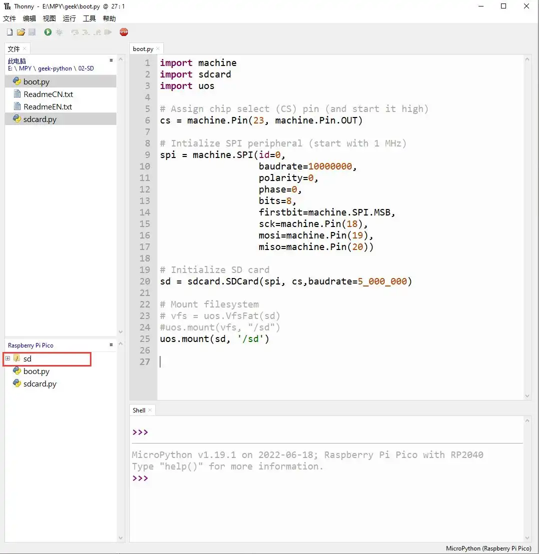
01_SD
Demo Description
- Uses SPI to communicate with the TF card and mounts the TF card to the development board. After successful mounting, you can view and modify the contents of the TF card via Thonny.
Hardware Connection
- Insert a TF card
- Connect the board to the computer using a USB cable
Code Analysis
sdcard.SDCard(spi, cs, baudrate): Creates a TF card object and binds the initialized SPI interface and CS pin to the TF card driver.uos.mount(sd, '/sd'): Mounts the TF card file system to the/sddirectory. After successful mounting, users can perform file read/write operations on the TF card via the/sdpath, such as creating, reading, or deleting files.
Operation Result
Upload all py files from the 01_SD folder to the development board via Thonny and reset the board. After resetting, the development board will automatically mount the TF card to the sd directory according to the boot.py program.
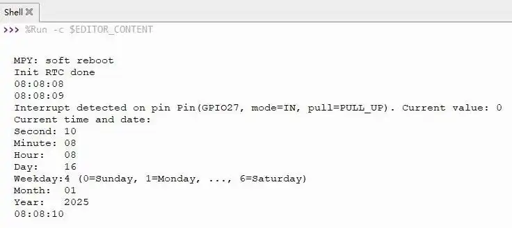
02_RTC
Demo Description
- Uses I2C to communicate with the onboard RTC chip, sets and reads RTC time data, and tests if the RTC interrupt is functioning correctly.
Hardware Connection
- Connect the board to the computer using a USB cable
Code Analysis
RTC = PCF85063(): Creates an RTC object.RTC.setDate(weekday, day, month, year): Sets the RTC date.RTC.setTime(hour, minute, second): Sets the RTC time.RTC.readTime(): Reads the RTC time.RTC.setAlarm(second, minute, hour, day, weekday): Sets the RTC alarm.RTC.enableAlarm(): Enables the RTC alarm.
Operation Result
Run the py files in the 02_RTC folder using Thonny.
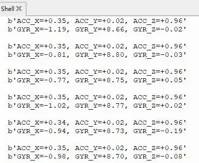
03_IMU
Demo Description
- Uses I2C to communicate with the onboard six-axis sensor and reads the sensor data.
Hardware Connection
- Connect the board to the computer using a USB cable
Code Analysis
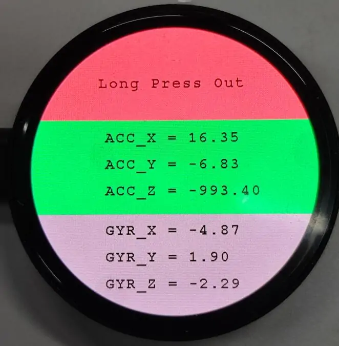
IMU = QMI8658(): Creates an IMU object.IMU.Read_XYZ(): Reads the six-axis sensor data.
Operation Result
Run the py files in the 03_IMU folder using Thonny.
04_GPS_UART
Demo Description
- Uses UART to communicate with the onboard GPS and queries the LC76G for NMEA data.
Hardware Connection
- Connect the GNSS ceramic antenna
- Connect the board to the computer using a USB cable
Code Analysis
gnss_l76b=l76x.L76X(): Creates a GPS object.gnss_l76b.l76x_send_command(): Sends initialization commands.gnss_l76b.uart_any(): Checks if there is data in the UART buffer.gnss_l76b.uart_receive_byte(): Receives UART data.
Operation Result
Upload all directories and files from the 04_GPS_UART folder to the development board using Thonny, then run the
coordinates_converted.pyfile in the example folder.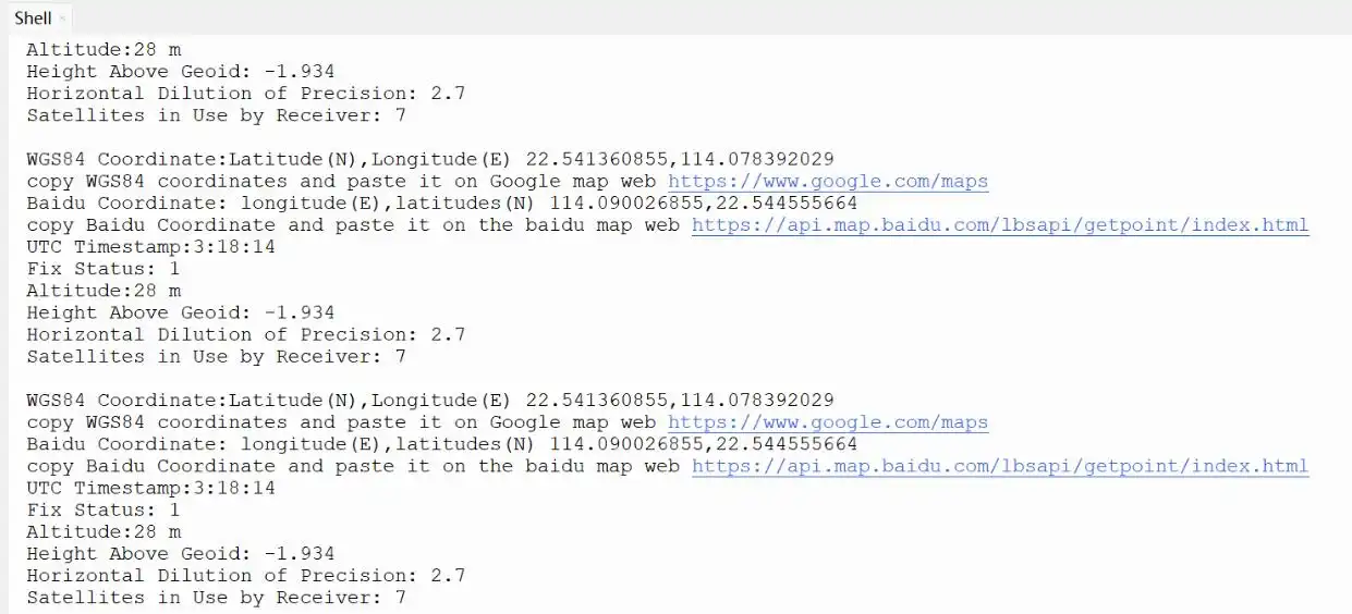
Working with C/C++
This chapter includes the following sections, please read as needed:
Setting Up Development Environment
Please refer to the Install and Configure Pico C/C++ Development Environment Tutorial to download and install the Pico VS Code.
Demo
The C/C++ demos are located in the C directory of the demo package.
| Demo | Basic Program Description | Dependency Library |
|---|---|---|
| 01_GUI | LCD GUI display program | - |
| 02_ES8311 | Development board audio test program | - |
| 03_FatFs | FAT file system, TF card supports SPI/SDIO communication | - |
| 04_GPS_I2C | Use I2C to communicate with GPS module and obtain GPS data | - |
| 05_LVGL | LCD LVGL display program | LVGL V8.1 |
01_GUI
Demo Description
- Uses PIO-emulated QSPI to communicate with the LCD and implements functions like displaying text and images via GUI.
Hardware Connection
- Connect the board to the computer using a USB cable
Code Analysis
Underlying Hardware Interface
We have encapsulated the hardware operations at a low level. Due to differences in hardware platforms, the internal implementations vary. If you need to understand the internal implementation, you can check the corresponding directory. Many definitions can be seen in DEV_Config.c(.h) under the directory: c\lib\Config.
Module initialization and exit handling
void DEV_Module_Init(void);
void DEV_Module_Exit(void);TIPThis handles GPIO operations before using the LCD and after finishing use.
GPIO read/write
void 	DEV_Digital_Write(uint_16 Pin, uint_8 Value);
uint_8 	DEV_Digital_Read(uint_16 Pin);
SPI write data
void DEV_SPI_WriteByte(uint_8 Value);
Upper Layer Applications
For the screen, what if you need to paint, display Chinese and English characters, display pictures, etc., these are all done by the upper layer applications. Many users have asked about graphical processing. We provide some basic functionalities in the GUI, located in the directory: c\lib\GUI\GUI_Paint.c(.h)
The character fonts that the GUI depends on are located in the directory: c\lib\Fonts
Create Image Attribute: Create a new image attribute, which includes the name, width, height, rotation angle, and color of the image cache.
void Paint_NewImage(uint16_t *image, uint16_t Width, uint16_t Height, uint16_t Rotate, uint16_t Color)
Parameters:
    image:  The name of the image cache, which is essentially a pointer to the starting address of the image cache;
    Width:  The width of the image cache;
    Height: The height of image cache;
    Rotate: The rotation angle of the image;
    Color:  The initial color of the image;
Select Image Cache: Selects an image cache. The purpose of this selection is to allow you to create multiple image attributes. Since multiple image caches can exist, you can select each image you have created.
void Paint_SelectImage(uint8_t *image)
Parameters:
    image: The name of the image cache, which is essentially a pointer to the starting address of the image cache;
Image Rotation: Set the rotation angle for the selected image. It is best to use this after Paint_SelectImage(). You can choose to rotate by 0, 90, 180, or 270 degrees.
void Paint_SetRotate(uint16_t Rotate)
Parameters:
Rotate: The image rotation angle. You can choose ROTATE_0, ROTATE_90, ROTATE_180, ROTATE_270 corresponding to 0, 90, 180, 270 degrees respectively.TIPThe starting pixel for coordinates differs under different rotation angles. Taking 1.14 as an example, the four images correspond to 0°, 90°, 180°, and 270° in order. This is for reference only.
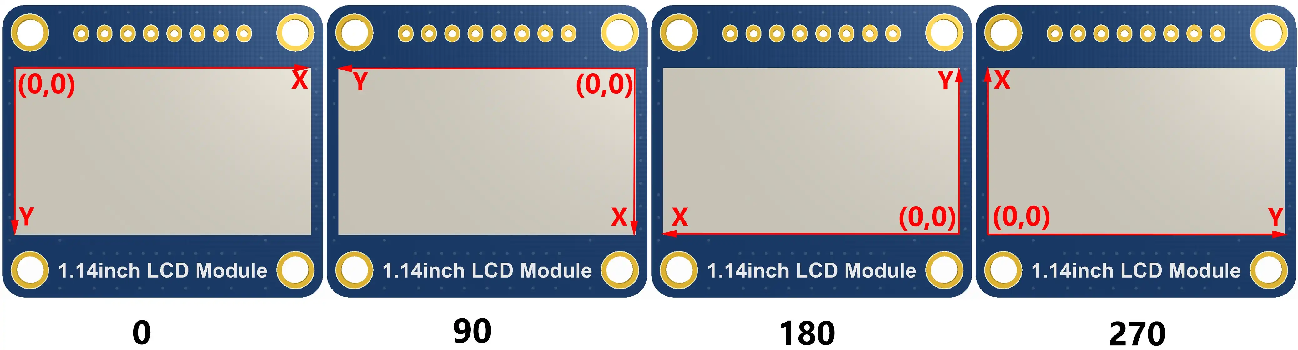
Image Mirroring: Set mirroring for the selected image. You can choose no mirroring, horizontal mirroring, vertical mirroring, or mirroring about the image center.
void Paint_SetMirroring(uint8_t mirror)
Parameters:
    mirror: The mirroring method for the image. You can choose MIRROR_NONE, MIRROR_HORIZONTAL, MIRROR_VERTICAL, MIRROR_ORIGIN corresponding to no mirroring, horizontal mirroring, vertical mirroring, and mirroring about the image center respectively.
Set Pixel Display Position and Color in Cache: This is one of the core GUI functions, handling the display position and color of a pixel within the cache.
void Paint_SetPixel(uint16_t Xpoint, uint16_t Ypoint, uint16_t Color)
Parameters:
    Xpoint: The X-coordinate of the point within the image cache;
    Ypoint: The Y-coordinate of the point within the image cache;
    Color:  The display color of the point;
Fill Image Cache with Color: Fills the image cache with a specific color, typically used to clear the screen to white.
void Paint_Clear(uint16_t Color)
Parameters:
    Color: The filled color
Fill Partial Window in Image Cache with Color: Fill a specific window area within the image cache with a color, often used to clear a window to white, such as when updating time displays to clear the previous second.
void Paint_ClearWindows(uint16_t Xstart, uint16_t Ystart, uint16_t Xend, uint16_t Yend, uint16_t Color)
Parameters:
    Xstart: The X starting coordinate of the window;
    Ystart: The Y starting coordinate of the window;
    Xend:   The X ending coordinate of the window;
    Yend:   The Y ending coordinate of the window;
    Color:  The filled color
Draw Dot: Draw a dot at (Xpoint, Ypoint) in the image cache. You can choose the color, the size, and the style of the dot.
void Paint_DrawPoint(uint16_t Xpoint, uint16_t Ypoint, uint16_t Color, DOT_PIXEL Dot_Pixel, DOT_STYLE Dot_Style)
Parameters:
    Xpoint: The X-coordinate of the dot;
    Ypoint: The Y-coordinate of the dot;
    Color:  The filled color
    Dot_Pixel: The size of the dot, with 8 default sizes provided:
        typedef enum {
            DOT_PIXEL_1X1  = 1, 	 	// 1 x 1
            DOT_PIXEL_2X2  , 		// 2 X 2
            DOT_PIXEL_3X3  , 	 	// 3 X 3
            DOT_PIXEL_4X4  , 	 	// 4 X 4
            DOT_PIXEL_5X5  , 		// 5 X 5
            DOT_PIXEL_6X6  , 		// 6 X 6
            DOT_PIXEL_7X7  , 		// 7 X 7
            DOT_PIXEL_8X8  , 		// 8 X 8
        } DOT_PIXEL;
    Dot_Style: The style of the dot, defining the method to expand the size of the dot is that, whether to expand from the dot as the center or from the dot as the lower left corner to the upper right.
        typedef enum {
        DOT_FILL_AROUND  = 1,
        DOT_FILL_RIGHTUP,
        } DOT_STYLE;
Draw Line: Draw a line from (Xstart, Ystart) to (Xend, Yend) in the image cache. You can select the color, line width, and line style.
void Paint_DrawLine(uint16_t Xstart, uint16_t Ystart, uint16_t Xend, uint16_t Yend, uint16_t Color, LINE_STYLE Line_Style , LINE_STYLE Line_Style)
Parameters:
    Xstart: The X starting coordinate of the line;
    Ystart: The Y starting coordinate of the line;
    Xend:   The X ending coordinate of the line;
    Yend:   The Y ending coordinate of the line;
    Color:  The filled color
    Line_width: The width of the line, with 8 default widths provided:
        typedef enum {
            DOT_PIXEL_1X1  = 1, 	 	// 1 x 1
            DOT_PIXEL_2X2  , 		// 2 X 2
            DOT_PIXEL_3X3  ,		// 3 X 3
            DOT_PIXEL_4X4  ,		// 4 X 4
            DOT_PIXEL_5X5  , 		// 5 X 5
            DOT_PIXEL_6X6  , 		// 6 X 6
            DOT_PIXEL_7X7  , 		// 7 X 7
            DOT_PIXEL_8X8  , 		// 8 X 8
        } DOT_PIXEL;
    Line_Style: The line style, choosing between solid line connection or dotted line connection
        typedef enum {
            LINE_STYLE_SOLID = 0,
            LINE_STYLE_DOTTED,
        } LINE_STYLE;
Draw Rectangle: Draw a rectangle from (Xstart, Ystart) to (Xend, Yend) in the image cache. You can select the color, line width, and whether to fill the interior of the rectangle.
void Paint_DrawRectangle(uint16_t Xstart, uint16_t Ystart, uint16_t Xend, uint16_t Yend, uint16_t Color, DOT_PIXEL Line_width, DRAW_FILL Draw_Fill)
Parameters:
    Xstart: The X starting coordinate of the rectangle;
    Ystart: The Y starting coordinate of the rectangle;
    Xend:   The X ending coordinate of the rectangle;
    Yend:   The Y ending coordinate of the rectangle;
    Color:  The filled color
    Line_width: The width of the rectangle's four sides, with 8 default widths provided:
        typedef enum {
            DOT_PIXEL_1X1  = 1, 	 	// 1 x 1
            DOT_PIXEL_2X2  , 		// 2 X 2
            DOT_PIXEL_3X3  ,		// 3 X 3
            DOT_PIXEL_4X4  ,		// 4 X 4
            DOT_PIXEL_5X5  , 		// 5 X 5
            DOT_PIXEL_6X6  , 		// 6 X 6
            DOT_PIXEL_7X7  , 		// 7 X 7
            DOT_PIXEL_8X8  , 		// 8 X 8
        } DOT_PIXEL;
    Draw_Fill: Fill option, determining whether to fill the interior of the rectangle:
        typedef enum {
            DRAW_FILL_EMPTY = 0,
            DRAW_FILL_FULL,
        } DRAW_FILL;
Draw Circle: Draw a circle with center at (X_Center, Y_Center) and a radius of Radius in the image cache, and you can choose the color. You can select the color, line width, and whether to fill the interior of the circle.
void Paint_DrawCircle(uint16_t X_Center, uint16_t Y_Center, uint16_t Radius, uint16_t Color, DOT_PIXEL Line_width, DRAW_FILL Draw_Fill)
Parameters:
    X_Center: The X-coordinate of the circle's center;
    Y_Center: The Y-coordinate of the circle's center;
    Radius:  The radius of the circle;
    Color:    The filled color
    Line_width: The width of the circle's arc, with 8 default widths provided:
        typedef enum {
            DOT_PIXEL_1X1  = 1, 	 	// 1 x 1
            DOT_PIXEL_2X2  , 		// 2 X 2
            DOT_PIXEL_3X3  ,		// 3 X 3
            DOT_PIXEL_4X4  ,		// 4 X 4
            DOT_PIXEL_5X5  , 		// 5 X 5
            DOT_PIXEL_6X6  , 		// 6 X 6
            DOT_PIXEL_7X7  , 		// 7 X 7
            DOT_PIXEL_8X8  , 		// 8 X 8
        } DOT_PIXEL;
    Draw_Fill: Fill option, determining whether to fill the interior of the circle:
        typedef enum {
            DRAW_FILL_EMPTY = 0,
            DRAW_FILL_FULL,
        } DRAW_FILL;
Draw Ascii Character: Draw an Ascii character in the image cache with (Xstart, Ystart) as the top-left vertex. You can select the Ascii visible character font, foreground color, and background color.
void Paint_DrawChar(uint16_t Xstart, uint16_t Ystart, const uint8_t Ascii_Char, sFONT* Font, uint16_t Color_Foreground, uint16_t Color_Background)
Parameters:
    Xstart: The X-coordinate of the number's top-left vertex;
    Ystart: The Y-coordinate of the number's top-left vertex;
    Ascii_Char: The Ascii character;
    Font: The Ascii visible character font. The following fonts are provided in the Fonts folder:
        font8: 5*8 font
        font12: 7*12 font
        font16: 11*16 font
        font20: 14*20 font
        font24: 17*24 font
    Color_Foreground: The font color;
    Color_Background: The background color;
Draw English String: Draw a string of English characters in the image cache with (Xstart, Ystart) as the top-left vertex. You can select the Ascii visible character font, foreground color, and background color.
void Paint_DrawString_EN(uint16_t Xstart, uint16_t Ystart, const uint8_t * pString, sFONT* Font, uint16_t Color_Foreground, uint16_t Color_Background)
Parameters:
    Xstart:  The X-coordinate of the number's top-left vertex;
    Ystart:  The Y-coordinate of the number's top-left vertex;
    pString: The string, which is a pointer;
    Font: The Ascii visible character font. The following fonts are provided in the Fonts folder:
        font8: 5*8 font
        font12: 7*12 font
        font16: 11*16 font
        font20: 14*20 font
        font24: 17*24 font
    Color_Foreground: The font color;
    Color_Background: The background color;
Draw Chinese String: Draw a string of Chinese characters in the image cache with (Xstart, Ystart) as the top-left vertex. You can select the GB2312 encoded character font, foreground color, and background color.
void Paint_DrawString_CN(uint16_t Xstart, uint16_t Ystart, const uint8_t * pString, cFONT* font, uint16_t Color_Foreground, uint16_t Color_Background)
Parameters:
    Xstart:  The X-coordinate of the number's top-left vertex;
    Ystart:  The Y-coordinate of the number's top-left vertex;
    pString: The string, which is a pointer;
    Font: The GB2312 encoded character font. The following fonts are provided in the Fonts folder:
        font12CN: Ascii character 11*21 font, Chinese 16*21 font
        font24CN: Ascii character 24*41 font, Chinese 32*41 font
    Color_Foreground: The font color;
    Color_Background: The background color;
Draw Number: Draw a number string in the image cache with (Xstart, Ystart) as the top-left vertex. You can select the Ascii visible character font, foreground color, background color, and decimal places.
void Paint_DrawNum(uint16_t Xpoint, uint16_t Ypoint, uint32_t Nummber, sFONT* Font, uint16_t Digit,uint16_t Color_Foreground, uint16_t Color_Background);
Parameters:
    Xstart:  The X-coordinate of the number's top-left vertex;
    Ystart:  The Y-coordinate of the number's top-left vertex;
    Number: The displayed number, here is stored in a 32-bit long int type, which can be displayed up to 2147483647.
    Font: The Ascii visible character font. The following fonts are provided in the Fonts folder:
        font8: 5*8 font
        font12: 7*12 font
        font16: 11*16 font
        font20: 14*20 font
        font24: 17*24 font
        Digit: The number of decimal places to display;
    Color_Foreground: The font color;
    Color_Background: The background color;
Display Time: Display a time period in the image cache with (Xstart, Ystart) as the top-left vertex. You can select the Ascii visible character font, foreground color, and background color.
void Paint_DrawTime(uint16_t Xstart, uint16_t Ystart, PAINT_TIME *pTime, sFONT* Font, uint16_t Color_Background, uint16_t Color_Foreground)
Parameters:
    Xstart: The X-coordinate of the number's top-left vertex;
    Ystart: The Y-coordinate of the number's top-left vertex;
    pTime:  The time to display, using a predefined time structure; simply pass the hour, minute, and second digits to the parameters;
    Font: The Ascii visible character font. The following fonts are provided in the Fonts folder:
        font8: 5*8 font
        font12: 7*12 font
        font16: 11*16 font
        font20: 14*20 font
        font24: 17*24 font
    Color_Foreground: The font color;
    Color_Background: The background color;
Operation Result
- Import and compile the 01_GUI project using VS Code. After compilation, flash the .uf2 file from the build directory, or directly flash 01_GUI.uf2 from the uf2 directory for quick verification.
02_ES8311
Demo Description
- Uses PIO-emulated I2S to communicate with ES8311, enabling audio input and output.
Hardware Connection
- Connect the speaker
- Connect the board to the computer using a USB cable
Code Analysis
es8311_init(): Initializes ES8311.es8311_sample_frequency_config(): Configures sampling rate.es8311_microphone_config(): Configures the microphone.es8311_microphone_gain_set(): Sets microphone gain.es8311_voice_volume_set(): Sets volume.Sine_440hz_out(): Outputs a 440 Hz sine wave.Happy_birthday_out(): Plays the "Happy Birthday" electronic melody.Loopback_test(): Audio recording and playback test.Music_out(): Plays music.
Operation Result
- Use VS Code to import and compile the 02_ES8311 project. After compilation, flash the .uf2 file from the build directory, or directly flash the uf2 file from the
02_ES8311\uf2directory for quick verification.
03_FatFs
Demo Description
- Uses SPI or PIO-emulated SDIO to communicate with the TF card, implementing a command-line interface similar to busybox or DOS.
Hardware Connection
- Insert a TF card
- Connect the board to the computer using a USB cable
Code Analysis
sd_init_driver(): Initializes the TF card driver.getchar_timeout_us(): Gets UART input.process_stdio(): Processes UART input.
Operation Result
Use a terminal tool like putty or mobaxterm to open the corresponding USB serial port of the development board.
Press the Enter key to start the command-line interface (CLI). You should see a prompt similar to this:
>Enter help command to get the available commands as follows
> help
setrtc <DD> <MM> <YY> <hh> <mm> <ss>:
Set Real Time Clock
Parameters: new date (DD MM YY) new time in 24-hour format (hh mm ss)
    e.g.:setrtc 16 3 21 0 4 0

date:
Print current date and time

lliot <drive#>:
!DESTRUCTIVE! Low Level I/O Driver Test
    e.g.: lliot 1

format [<drive#:>]:
Creates an FAT/exFAT volume on the logical drive.
    e.g.: format 0:

mount [<drive#:>]:
Register the work area of the volume
    e.g.: mount 0:

unmount <drive#:>:
Unregister the work area of the volume

chdrive <drive#:>:
Changes the current directory of the logical drive.
<path> Specifies the directory to be set as current directory.
    e.g.: chdrive 1:

getfree [<drive#:>]:
Print the free space on drive

cd <path>:
Changes the current directory of the logical drive.
<path> Specifies the directory to be set as current directory.
    e.g.: cd 1:/dir1

mkdir <path>:
Make a new directory.
<path> Specifies the name of the directory to be created.
    e.g.: mkdir /dir1

ls:
List directory

cat <filename>:
Type file contents

simple:
Run simple FS tests

big_file_test <pathname> <size in bytes> <seed>:
Writes random data to file <pathname>.
<size in bytes> must be multiple of 512.
    e.g.: big_file_test bf 1048576 1
    or: big_file_test big3G-3 0xC0000000 3

cdef:
Create Disk and Example Files
Expects card to be already formatted and mounted

start_logger:
Start Data Log Demo

stop_logger:
Stop Data Log Demo
04_GPS_I2C
Demo Description
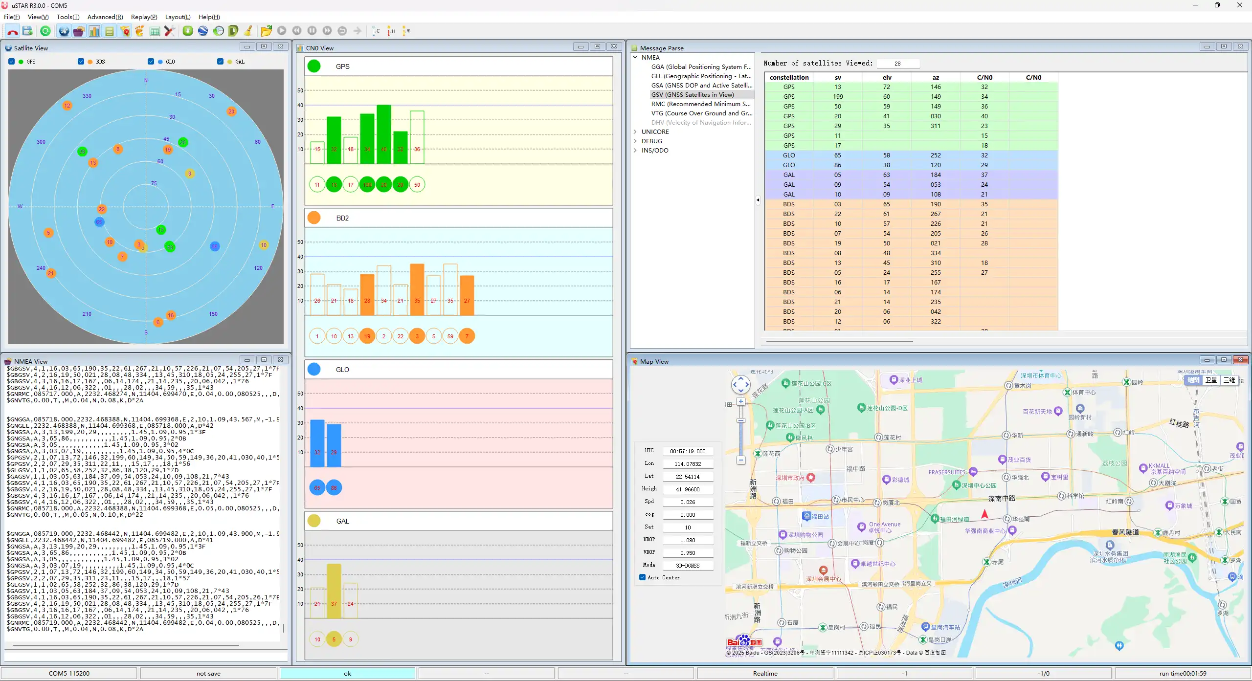
- This example demonstrates actively querying the LC76G for NMEA data using I2C. The transmitted data is printed to the serial port, allowing direct use of an NMEA parsing tool to obtain information such as latitude and longitude.
Hardware Connection
- Connect the GNSS ceramic antenna
- Connect the board to the computer using a USB cable
Code Analysis
i2c_master_init(): Initializes I2C.writeDataToI2C(): Sends commands and reads data.
Operation Result
Use VS Code to import and compile the 04_GPS_I2C project. After compilation, flash the .uf2 file from the build directory, or directly flash the 04_GPS_I2C.uf2 file from the uf2 directory for quick verification.
05_LVGL
Demo Description
- Uses PIO-emulated QSPI to communicate with the LCD and implements functions like displaying text and images via LVGL.
Hardware Connection
- Connect the board to the computer using a USB cable
Code Analysis
Source Code Structure
The source code of the LVGL library is located in
lib\lvglof the project folder, version 8.1. For secondary development, please refer to the corresponding version's development documentation.LVGL library related settings are in
examples\inc\lv_conf.hof the project folder, where you can set display refresh rate, system data usage, etc.The application code for the LVGL library is located in
examples\src\LVGL_example.cof the project folder.
LVGL Initialization
Before using the LVGL graphics library, you need to initialize LVGL.
LVGL Library Initialization Function
Location:
examples\src\LVGL_example.cFunction: Mainly used to initialize the hardware and structure variables required by LVGL.
LVGL_Init();LVGL Core Initialization
Location:
examples\src\LVGL_example.c/*2.Init LVGL core*/
lv_init();
LVGL Run
The LVGL library calls the heartbeat function lv_tick_inc at regular intervals to notify LVGL of the elapsed time so that LVGL can update its internal time state and handle time-related tasks such as animations, timers, etc. The lv_task_handler function also needs to be called in the loop of the main function so that LVGL can handle events and tasks in time to ensure that the user interface responds and refreshes.
LVGL Heartbeat Interface
Location:
examples\src\LVGL_example.cImplementation: Ensure the priority of
lv_task_handleris lower than that oflv_tick_inc. In this example,lv_tick_incis called in the timer callback function.//Timer callback is called every 5ms
add_repeating_timer_ms(5, repeating_lvgl_timer_callback, NULL, &lvgl_timer);
static bool repeating_lvgl_timer_callback(struct repeating_timer *t)
{
lv_tick_inc(5);
return true;
}LVGL Task Handler
Location:
examples\src\LCD_XinXX_LVGL_test.cImplementation: To handle LVGL tasks,
lv_timer_handler()needs to be called periodically. In this example, it's called in the main function loop.int main()
{
...
while (1)
{
lv_task_handler();
DEV_Delay_ms(5);
...
}
}
LVGL Display
To implement LVGL display, you must initialize a display driver and set the various properties of the display driver, such as color format, draw buffer, rendering mode, and display callback function. At each LV_DISP_DEF_REFR_PERIOD (set in lv_conf.h), LVGL detects if something has happened on the UI that needs to be redrawn. For example, a button is pressed, a chart is changed, an animation occurs, etc. When redrawing is needed, LVGL calls the display callback function to complete the drawing of the image in the refresh area.
LVGL Display Refresh Rate Setting
Location:
examples\inc\lv_conf.hSetting: You can also set the refresh period time for the display buffer in
lv_conf.h. Modify this definition to change the screen refresh time.#define LV_DISP_DEF_REFR_PERIOD 10 // Unit: ms, here is 10msLVGL Display Color Setting
Location:
examples\inc\lv_conf.hPurpose: Since the pixel color storage method constructed by the
lv_color_tstructure by default is inconsistent with the data format required for transmission in this example, direct transmission would cause color differences in the displayed image.#define LV_COLOR_16_SWAP 1LVGL Display Related Variable Definitions
Location:
examples\src\LVGL_example.cFunction: Defines the display driver
disp_drvand drawing bufferdisp_buf. In this example, the drawing bufferbuf0is set to the entire screen area, which can effectively reduce aliasing during full-screen refreshes and improve screen refresh rate.static lv_disp_drv_t disp_drv;
static lv_disp_draw_buf_t disp_buf;
static lv_color_t *buf0;LVGL Display Device Registration
Location:
examples\src\LVGL_example.cFunction: Completes the LVGL core structure variables according to design requirements, initializes the display driver
disp_drv, and sets the drawing buffer, which is a simple array used by LVGL to render screen content. Once rendering is ready, the content of the drawing buffer is sent to the display using thedisp_drv_flush_cbfunction set in the display driver./*3.Init LVGL display*/
buf0 = (lv_color_t *)malloc(DISP_HOR_RES * DISP_VER_RES);
lv_disp_draw_buf_init(&disp_buf, buf0, NULL, DISP_HOR_RES * DISP_VER_RES);
lv_disp_drv_init(&disp_drv);
disp_drv.flush_cb = disp_flush_cb;
disp_drv.draw_buf = &disp_buf;
disp_drv.hor_res = DISP_HOR_RES;
disp_drv.ver_res = DISP_VER_RES;
lv_disp_t *disp= lv_disp_drv_register(&disp_drv);LVGL Display Callback Function
Location:
examples\src\LVGL_example.cFunction: Mainly completes the drawing of the image in the refresh area.
void disp_flush( lv_disp_drv_t *disp_drv, const lv_area_t *area, lv_color_t *color_p )
Parameters:
    lv_disp_drv_t *disp_drv: Displays driver structure pointers, which contain information about the display and function pointers. This parameter is often used to notify you that the refresh is complete
    const lv_area_t *area  : Region structure pointer, containing the position information of the area to be refreshed. In this demo, you can use it for creating TFT display window.
    lv_color_t *color_p    : Color structure pointer, indicating the color data to be displayed in the refresh area. In this demo, it reads the address as DMA input to transmit data to the QSPI bus and completes the image drawing
LVGL Display Callback Function Implementation
Location:
examples\src\LVGL_example.cImplementation: In this example, to minimize processor utilization, DMA is used for color data transfer.
color_pis set as the read address, and the QSPI interface's TX FIFO register is set as the write address.static void disp_flush_cb(lv_disp_drv_t * disp, const lv_area_t * area, lv_color_t * color_p)
{
AMOLED_1IN75_SetWindows(area->x1, area->y1, area->x2+1 , area->y2+1); // Set the LVGL interface display position
QSPI_Select(qspi);
QSPI_Pixel_Write(qspi, 0x2c);
dma_channel_configure(dma_tx,
&c,
&qspi.pio->txf[qspi.sm],
color_p, // read address
((area->x2 + 1 - area->x1) * (area->y2 + 1 - area->y1))*2,
true);// Start DMA transfer
}LVGL Refresh Completion Notification Implementation
Location:
examples\src\LVGL_example.cFunction: After each image refresh is complete, the LVGL core needs to be notified so that LVGL can prepare to render the next refresh image.
Implementation: This example notifies LVGL image refresh completion in the DMA transfer complete interrupt service function.
static void dma_handler(void)
{
    if (dma_channel_get_irq0_status(dma_tx))
    {
        dma_channel_acknowledge_irq0(dma_tx);
        QSPI_Deselect(qspi);
        lv_disp_flush_ready(&disp_drv); // Indicate you are ready with the flushing
    }
}
LVGL Input
In LVGL, users can register input devices such as touchpads, mice, keyboards, or encoders, etc. Users can control the user interface through these input devices to achieve better interaction.
LVGL Input Device Callback Function Call Frequency Setting
Location:
examples\inc\lv_conf.hSetting: LVGL calls the input device callback function every 30ms by default to update events triggered by the input device. This can be set in
lv_conf.h.#define LV_INDEV_DEF_READ_PERIOD 30 // Unit: ms, here is 30msLVGL Input Device Registration
Location:
examples\src\LVGL_example.cSetting: Register the touch screen device
indev_tsand initialize it./*4.Init touch screen as input device*/
lv_indev_drv_init(&indev_ts); // Device initialization
indev_ts.type = LV_INDEV_TYPE_POINTER; // Register as touch screen device
indev_ts.read_cb = ts_read_cb; // Set callback function
lv_indev_t * ts_indev = lv_indev_drv_register(&indev_ts); // Register device
//Enable IRQ
DEV_KEY_Config(Touch_INT_PIN);
DEV_IRQ_SET(Touch_INT_PIN, GPIO_IRQ_EDGE_RISE, &touch_callback);
DEV_KEY_Config(SYS_OUT);
DEV_IRQ_SET(SYS_OUT, GPIO_IRQ_EDGE_FALL, &touch_callback);LVGL Input Device Callback Function
Location:
examples\src\LVGL_example.cFunction: Mainly used to update input events.
static void ts_read_cb(lv_indev_drv_t * drv, lv_indev_data_t*data);
Parameters:
lv_indev_drv_t *indev_drv: Pointer to the input device driver structure in LVGL. In this case, the structure is a touch screen input device driver
lv_indev_data_t *data    : Pointer to the input device data structure in LVGL. In this case, the structure is used to store the status and data of the input device, including the current touch state (pressed or released) and the coordinates of the touch points
Touch Screen Input Device Callback Function Implementation
Location:
examples\src\LVGL_example.cImplementation: Mainly updates the touch screen's touch state and touch point coordinates through touch interrupts.
static void touch_callback(uint gpio, uint32_t events)
{
    if (gpio == TOUCH_INT_PIN)
    {
        CST9217_Read_Data(); // Get coordinate data
        ts_x = CST9217.data[0].x;
        ts_y = CST9217.data[0].y;
        ts_act = LV_INDEV_STATE_PRESSED;
    }
    else if(gpio == SYS_OUT)
    {
        watchdog_reboot(0,0,0);
    }
}

static void ts_read_cb(lv_indev_drv_t * drv, lv_indev_data_t*data)
{
    data->point.x = ts_x;
    data->point.y = ts_y;
    data->state = ts_act;
    ts_act = LV_INDEV_STATE_RELEASED;
}
LVGL Widget Layout
In LVGL, we can create various user interfaces. The basic components of the interface are objects, also called widgets, such as buttons, labels, images, lists, charts, or text areas. In a interface, we can create multiple widgets simultaneously and set their positions, sizes, parent objects, styles, and event handlers and other basic properties.
LVGL Widget Initialization
Location:
examples\src\LVGL_example.cFunction: Mainly used for styling and laying out widgets.
void Widgets_Init(void);LVGL Create Tile
Location:
examples\src\LVGL_example.cFunction: A Tile view is a container object whose elements (called tiles) can be arranged in a grid. Users can navigate between tiles by swiping. Call
lv_tileview_add_tile(tileview, row_id, col_id, dir)to create a new tile at rowrow_idand columncol_id.dircan beLV_DIR_LEFT/RIGHT/TOP/BOTTOM/HOR/VER/ALLor values to allow sliding to adjacent tiles in the given direction.//Create a tile at (0,0), supporting sliding down to (0, 1
tile1 = lv_tileview_add_tile(tv, 0, 0, LV_DIR_BOTTOM);LVGL Create Widget
Location:
examples\src\LVGL_example.cFunction: Create a widget. Different widgets require different function interfaces, and you can choose a parent object for creation.
//Create a widget where tab1 is the parent object of the key, which can be replaced with a widget such as list, title, etc. that can have child objects
sw = lv_switch_create(tab1);
LVGL Widget Alignment and Positioning
Location:
examples\src\LVGL_example.cFunction: Enables widgets to be positioned with offset based on a reference point. The widget aligns to the center of the offset reference point widget.
Alignment standard: The LVGL library supports both internal and external alignments. By default, the upper-left corner is the origin, the leftward as the positive horizontal direction, and the downward as the positive vertical direction.
//Position the btn widget at the center point, offset 45 pixels to the left
lv_obj_align(sw, LV_ALIGN_CENTER, -45, 0);
LVGL Widget Font Size Switching
Location:
examples\inc\lv_conf.h,examples\src\LVGL_example.cFunction: In practical applications, one interface may require multiple font sizes. You can enable multiple font sizes in
lv_conf.hand set the default font size. When setting font size, the widget needs to be styled so that it can be rendered according to the set style. Using thelv_obj_add_stylefunction, different parts of the widget can be rendered in different states.#define LV_FONT_MONTSERRAT_16 1 // Enable 16pt font
#define LV_FONT_MONTSERRAT_18 1 // Enable 18pt font
#define LV_FONT_DEFAULT &lv_font_montserrat_18 // Set default font size to 18pt
static lv_style_t style_label;
lv_style_init(&style_label); // Initialize style
lv_style_set_text_font(&style_label, &lv_font_montserrat_16); // Set font size to 16pt
lv_obj_add_style(label,&style_label,0); // Set label theme styleLVGL Widget Event Handling
Location:
examples\src\LVGL_example.cFunction: In LVGL, you can add event handling callback functions to widgets so that when events like clicks, scrolls, or redraws occur on the widget, the event is triggered, and the event handling callback function is entered. In the program, call
lv_obj_add_event_cb(obj, event_cb, filter, user_data)to add an event handlerevent_cbfor thefilterevent to widgetobj. When widgetobjtriggers thefilterevent, the system automatically calls theevent_cbfunction. The last parameter is a pointer to any custom data available in the event.//Add an event handler sw_event_cb for the LV_EVENT_VALUE_CHANGED event to the sw widget
lv_obj_add_event_cb(sw, sw_event_cb,LV_EVENT_VALUE_CHANGED,NULL);
Operation Result
Use VS Code to import and compile the 05_LVGL project. After compilation, flash the .uf2 file from the build directory, or directly flash the 05_LVGL.uf2 file from the uf2 directory for quick verification.
Working with Arduino
This chapter includes the following sections, please read as needed:
Setting Up Development Environment
Please refer to the Install and Configure Arduino IDE Tutorial to download and install the Arduino IDE.
Demo
The Arduino demos are located in the Arduino directory of the demo package.
| Demo | Basic Program Description | Dependency Library |
|---|---|---|
| 01_GUI | LCD GUI Display Program | - |
| 02_LVGL | LCD LVGL Display Program | LVGL V8.2 |
01_GUI
Demo Description
- Uses PIO-emulated QSPI to communicate with the LCD and implements functions like displaying text and images via GUI.
Hardware Connection
- Connect the board to the computer using a USB cable
Code Analysis
Underlying Hardware Interface
We have encapsulated the hardware operations at a low level. Due to differences in hardware platforms, the internal implementations vary. If you need to understand the internal implementation, you can check the corresponding directory. Many definitions can be seen in DEV_Config.c(.h) under the directory: c\lib\Config.
Module initialization and exit handling
void DEV_Module_Init(void);
void DEV_Module_Exit(void);TIPThis handles GPIO operations before using the LCD and after finishing use.
GPIO read/write
void 	DEV_Digital_Write(uint_16 Pin, uint_8 Value);
uint_8 	DEV_Digital_Read(uint_16 Pin);
SPI write data
void DEV_SPI_WriteByte(uint_8 Value);
Upper Layer Applications
For the screen, what if you need to paint, display Chinese and English characters, display pictures, etc., these are all done by the upper layer applications. Many users have asked about graphical processing. We provide some basic functionalities in the GUI, located in the directory: c\lib\GUI\GUI_Paint.c(.h)
![]()
The character fonts that the GUI depends on are located in the directory: c\lib\Fonts

Create Image Attribute: Create a new image attribute, which includes the name, width, height, rotation angle, and color of the image cache.
void Paint_NewImage(uint16_t *image, uint16_t Width, uint16_t Height, uint16_t Rotate, uint16_t Color)
Parameters:
    image:  The name of the image cache, which is essentially a pointer to the starting address of the image cache;
    Width:  The width of the image cache;
    Height: The height of image cache;
    Rotate: The rotation angle of the image;
    Color:  The initial color of the image;
Select Image Cache: Selects an image cache. The purpose of this selection is to allow you to create multiple image attributes. Since multiple image caches can exist, you can select each image you have created.
void Paint_SelectImage(uint8_t *image)
Parameter:
    image: The name of the image cache, which is essentially a pointer to the starting address of the image cache;
Image Rotation: Set the rotation angle for the selected image. It is best to use this after Paint_SelectImage(). You can choose to rotate by 0, 90, 180, or 270 degrees.
void Paint_SetRotate(uint16_t Rotate)
Parameter:
Rotate: The image rotation angle. You can choose ROTATE_0, ROTATE_90, ROTATE_180, ROTATE_270 corresponding to 0, 90, 180, 270 degrees respectively.TIPThe starting pixel for coordinates differs under different rotation angles. Taking 1.14 as an example, the four images correspond to 0°, 90°, 180°, and 270° in order. This is for reference only.
Image Mirroring: Set mirroring for the selected image. You can choose no mirroring, horizontal mirroring, vertical mirroring, or mirroring about the image center.
void Paint_SetMirroring(uint8_t mirror)
Parameter:
    mirror: The mirroring method for the image. You can choose MIRROR_NONE, MIRROR_HORIZONTAL, MIRROR_VERTICAL, MIRROR_ORIGIN corresponding to no mirroring, horizontal mirroring, vertical mirroring, and mirroring about the image center respectively.
Set Pixel Display Position and Color in Cache: This is one of the core GUI functions, handling the display position and color of a pixel within the cache.
void Paint_SetPixel(uint16_t Xpoint, uint16_t Ypoint, uint16_t Color)
Parameters:
    Xpoint: The X-coordinate of the point within the image cache;
    Ypoint: The Y-coordinate of the point within the image cache;
    Color:  The display color of the point;
Fill Image Cache with Color: Fills the image cache with a specific color, typically used to clear the screen to white.
void Paint_Clear(uint16_t Color)
Parameter:
    Color: The filled color
Fill Partial Window in Image Cache with Color: Fill a specific window area within the image cache with a color, often used to clear a window to white, such as when updating time displays to clear the previous second.
void Paint_ClearWindows(uint16_t Xstart, uint16_t Ystart, uint16_t Xend, uint16_t Yend, uint16_t Color)
Parameters:
    Xstart: The X starting coordinate of the window;
    Ystart: The Y starting coordinate of the window;
    Xend:   The X ending coordinate of the window;
    Yend:   The Y ending coordinate of the window;
    Color:  The filled color
Draw Dot: Draw a dot at (Xpoint, Ypoint) in the image cache. You can choose the color, the size, and the style of the dot.
void Paint_DrawPoint(uint16_t Xpoint, uint16_t Ypoint, uint16_t Color, DOT_PIXEL Dot_Pixel, DOT_STYLE Dot_Style)
Parameters:
    Xpoint: The X-coordinate of the dot;
    Ypoint: The Y-coordinate of the dot;
    Color:  The filled color
    Dot_Pixel: The size of the dot, with 8 default sizes provided:
        typedef enum {
            DOT_PIXEL_1X1  = 1, 	 	// 1 x 1
            DOT_PIXEL_2X2  , 		// 2 X 2
            DOT_PIXEL_3X3  , 	 	// 3 X 3
            DOT_PIXEL_4X4  , 	 	// 4 X 4
            DOT_PIXEL_5X5  , 		// 5 X 5
            DOT_PIXEL_6X6  , 		// 6 X 6
            DOT_PIXEL_7X7  , 		// 7 X 7
            DOT_PIXEL_8X8  , 		// 8 X 8
        } DOT_PIXEL;
    Dot_Style: The style of the dot, defining the method to expand the size of the dot is that, whether to expand from the dot as the center or from the dot as the lower left corner to the upper right.
        typedef enum {
        DOT_FILL_AROUND  = 1,
        DOT_FILL_RIGHTUP,
        } DOT_STYLE;
Draw Line: Draw a line from (Xstart, Ystart) to (Xend, Yend) in the image cache. You can select the color, line width, and line style.
void Paint_DrawLine(uint16_t Xstart, uint16_t Ystart, uint16_t Xend, uint16_t Yend, uint16_t Color, LINE_STYLE Line_Style , LINE_STYLE Line_Style)
Parameters:
    Xstart: The X starting coordinate of the line;
    Ystart: The Y starting coordinate of the line;
    Xend:   The X ending coordinate of the line;
    Yend:   The Y ending coordinate of the line;
    Color:  The filled color
    Line_width: The width of the line, with 8 default widths provided:
        typedef enum {
            DOT_PIXEL_1X1  = 1, 	 	// 1 x 1
            DOT_PIXEL_2X2  , 		// 2 X 2
            DOT_PIXEL_3X3  ,		// 3 X 3
            DOT_PIXEL_4X4  ,		// 4 X 4
            DOT_PIXEL_5X5  , 		// 5 X 5
            DOT_PIXEL_6X6  , 		// 6 X 6
            DOT_PIXEL_7X7  , 		// 7 X 7
            DOT_PIXEL_8X8  , 		// 8 X 8
        } DOT_PIXEL;
    Line_Style: The line style, choosing between solid line connection or dotted line connection
        typedef enum {
            LINE_STYLE_SOLID = 0,
            LINE_STYLE_DOTTED,
        } LINE_STYLE;
Draw Rectangle: Draw a rectangle from (Xstart, Ystart) to (Xend, Yend) in the image cache. You can select the color, line width, and whether to fill the interior of the rectangle.
void Paint_DrawRectangle(uint16_t Xstart, uint16_t Ystart, uint16_t Xend, uint16_t Yend, uint16_t Color, DOT_PIXEL Line_width, DRAW_FILL Draw_Fill)
Parameters:
    Xstart: The X starting coordinate of the rectangle;
    Ystart: The Y starting coordinate of the rectangle;
    Xend:   The X ending coordinate of the rectangle;
    Yend:   The Y ending coordinate of the rectangle;
    Color:  The filled color
    Line_width: The width of the rectangle's four sides, with 8 default widths provided:
        typedef enum {
            DOT_PIXEL_1X1  = 1, 	 	// 1 x 1
            DOT_PIXEL_2X2  , 		// 2 X 2
            DOT_PIXEL_3X3  ,		// 3 X 3
            DOT_PIXEL_4X4  ,		// 4 X 4
            DOT_PIXEL_5X5  , 		// 5 X 5
            DOT_PIXEL_6X6  , 		// 6 X 6
            DOT_PIXEL_7X7  , 		// 7 X 7
            DOT_PIXEL_8X8  , 		// 8 X 8
        } DOT_PIXEL;
    Draw_Fill: Fill option, determining whether to fill the interior of the rectangle:
        typedef enum {
            DRAW_FILL_EMPTY = 0,
            DRAW_FILL_FULL,
        } DRAW_FILL;
Draw Circle: Draw a circle with center at (X_Center, Y_Center) and a radius of Radius in the image cache, and you can choose the color. You can select the color, line width, and whether to fill the interior of the circle.
void Paint_DrawCircle(uint16_t X_Center, uint16_t Y_Center, uint16_t Radius, uint16_t Color, DOT_PIXEL Line_width, DRAW_FILL Draw_Fill)
Parameters:
    X_Center: The X-coordinate of the circle's center;
    Y_Center: The Y-coordinate of the circle's center;
    Radius:  The radius of the circle;
    Color:    The filled color
    Line_width: The width of the circle's arc, with 8 default widths provided:
        typedef enum {
            DOT_PIXEL_1X1  = 1, 	 	// 1 x 1
            DOT_PIXEL_2X2  , 		// 2 X 2
            DOT_PIXEL_3X3  ,		// 3 X 3
            DOT_PIXEL_4X4  ,		// 4 X 4
            DOT_PIXEL_5X5  , 		// 5 X 5
            DOT_PIXEL_6X6  , 		// 6 X 6
            DOT_PIXEL_7X7  , 		// 7 X 7
            DOT_PIXEL_8X8  , 		// 8 X 8
        } DOT_PIXEL;
    Draw_Fill: Fill option, determining whether to fill the interior of the circle:
        typedef enum {
            DRAW_FILL_EMPTY = 0,
            DRAW_FILL_FULL,
        } DRAW_FILL;
Draw Ascii Character: Draw an Ascii character in the image cache with (Xstart, Ystart) as the top-left vertex. You can select the Ascii visible character font, foreground color, and background color.
void Paint_DrawChar(uint16_t Xstart, uint16_t Ystart, const uint8_t Ascii_Char, sFONT* Font, uint16_t Color_Foreground, uint16_t Color_Background)
Parameters:
    Xstart: The X-coordinate of the character's top-left vertex;
    Ystart: The Y-coordinate of the character's top-left vertex;
    Ascii_Char: The Ascii character;
    Font: The Ascii visible character font. The following fonts are provided in the Fonts folder:
        font8: 5*8 font
        font12: 7*12 font
        font16: 11*16 font
        font20: 14*20 font
        font24: 17*24 font
    Color_Foreground: The font color;
    Color_Background: The background color;
Draw English String: Draw a string of English characters in the image cache with (Xstart, Ystart) as the top-left vertex. You can select the Ascii visible character font, foreground color, and background color.
void Paint_DrawString_EN(uint16_t Xstart, uint16_t Ystart, const uint8_t * pString, sFONT* Font, uint16_t Color_Foreground, uint16_t Color_Background)
Parameters:
    Xstart:  The X-coordinate of the string's top-left vertex;
    Ystart:  The Y-coordinate of the string's top-left vertex;
    pString: The string, which is a pointer;
    Font: The Ascii visible character font. The following fonts are provided in the Fonts folder:
        font8: 5*8 font
        font12: 7*12 font
        font16: 11*16 font
        font20: 14*20 font
        font24: 17*24 font
    Color_Foreground: The font color;
    Color_Background: The background color;
Draw Chinese String: Draw a string of Chinese characters in the image cache with (Xstart, Ystart) as the top-left vertex. You can select the GB2312 encoded character font, foreground color, and background color.
void Paint_DrawString_CN(uint16_t Xstart, uint16_t Ystart, const uint8_t * pString, cFONT* font, uint16_t Color_Foreground, uint16_t Color_Background)
Parameters:
    Xstart:  The X-coordinate of the string's top-left vertex;
    Ystart:  The Y-coordinate of the string's top-left vertex;
    pString: The string, which is a pointer;
    Font: The GB2312 encoded character font. The following fonts are provided in the Fonts folder:
        font12CN: Ascii character 11*21 font, Chinese 16*21 font
        font24CN: Ascii character 24*41 font, Chinese 32*41 font
    Color_Foreground: The font color;
    Color_Background: The background color;
Draw Number: Draw a number string in the image cache with (Xstart, Ystart) as the top-left vertex. You can select the Ascii visible character font, foreground color, background color, and decimal places.
void Paint_DrawNum(uint16_t Xpoint, uint16_t Ypoint, uint32_t Nummber, sFONT* Font, uint16_t Digit,uint16_t Color_Foreground, uint16_t Color_Background);
Parameters:
    Xstart:  The X-coordinate of the number's top-left vertex;
    Ystart:  The Y-coordinate of the number's top-left vertex;
    Number: The displayed number, here is stored in a 32-bit long int type, which can be displayed up to 2147483647.
    Font: The Ascii visible character font. The following fonts are provided in the Fonts folder:
        font8: 5*8 font
        font12: 7*12 font
        font16: 11*16 font
        font20: 14*20 font
        font24: 17*24 font
        Digit: The number of decimal places to display;
    Color_Foreground: The font color;
    Color_Background: The background color;
Display Time: Display a time period in the image cache with (Xstart, Ystart) as the top-left vertex. You can select the Ascii visible character font, foreground color, and background color.
void Paint_DrawTime(uint16_t Xstart, uint16_t Ystart, PAINT_TIME *pTime, sFONT* Font, uint16_t Color_Background, uint16_t Color_Foreground)
Parameters:
    Xstart: The X-coordinate of the time display's top-left vertex;
    Ystart: The Y-coordinate of the time display's top-left vertex;
    pTime:  The time to display, using a predefined time structure; simply pass the hour, minute, and second digits to the parameters;
    Font: The Ascii visible character font. The following fonts are provided in the Fonts folder:
        font8: 5*8 font
        font12: 7*12 font
        font16: 11*16 font
        font20: 14*20 font
        font24: 17*24 font
    Color_Foreground: Font color
    Color_Background: Background color
Operation Result
- Import and compile the 01_GUI project using VS Code. After compilation, flash the .uf2 file from the build directory, or directly flash 01_GUI.uf2 from the uf2 directory for quick verification.
02_LVGL
Environment Configuration
Install the LVGL Library
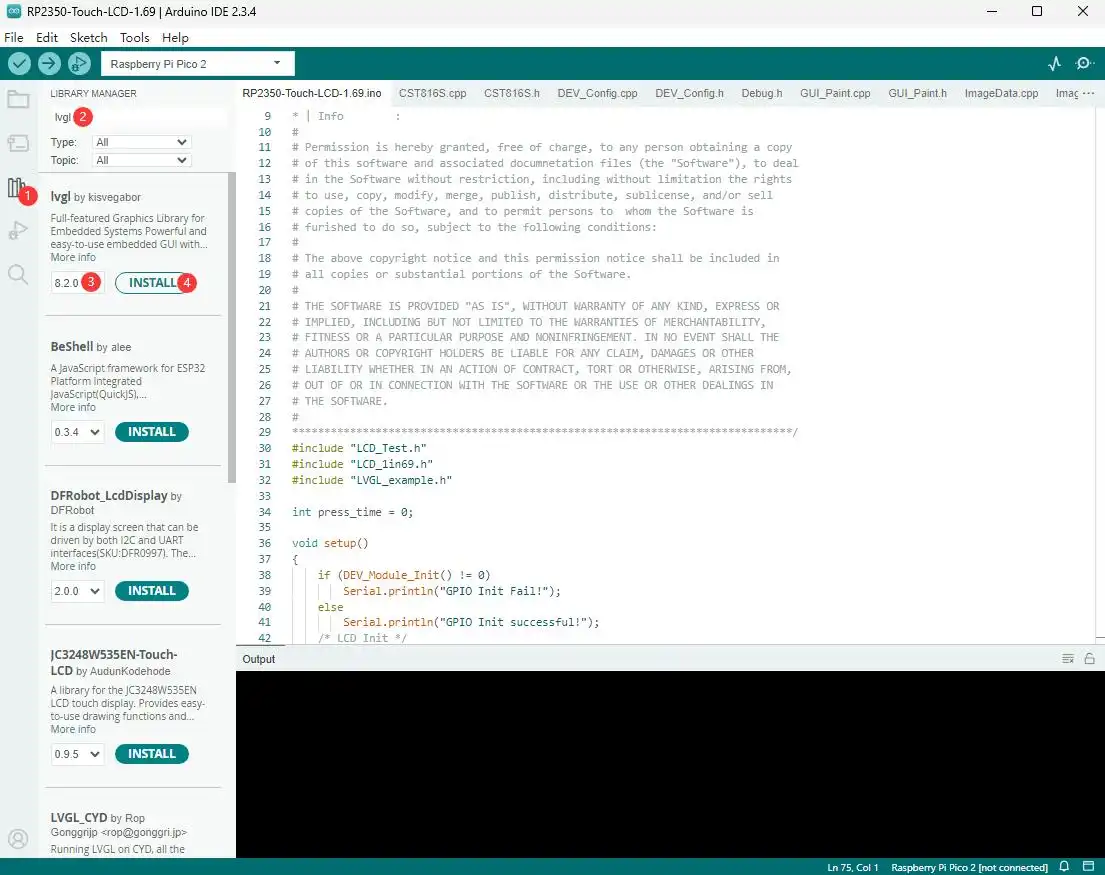
1.Click the third icon on the left sidebar or go to the menu bar and click "Tools" > "Manage Libraries..."
2.Enter "lvgl" in the search box and find the "lvgl" library.
3.Select version 8.2.0.
4.Click the "INSTALL" button to install it.Add Configuration File
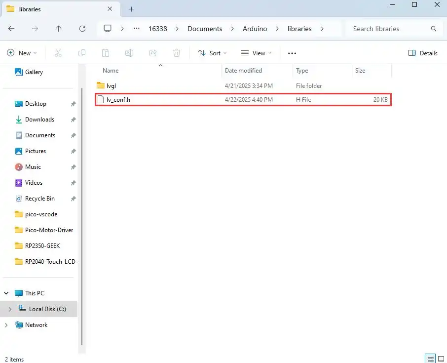
1.LVGL has its own configuration file named
lv_conf.h.
2.Go to the directory of the installed Arduino libraries. Here you can see the directory of the lvgl library we installed.
3.Download the program package and copyArduino\lv_conf.hfrom the package to your local Arduino library directory.
4.The final layout should look like this:arduino
|-libraries
|-lvgl
|-other_lib_1
|-other_lib_2
|-lv_conf.h
Demo Description
- Uses PIO-emulated QSPI to communicate with the LCD and implements functions like displaying text and images via LVGL.
Hardware Connection
- Connect the board to the computer using a USB cable
Code Analysis
Source Code Structure
The source code of the LVGL library is located in
lib\lvglof the project folder, version 8.1. For secondary development, please refer to the corresponding version's development documentation.LVGL library related settings are in
examples\inc\lv_conf.hof the project folder, where you can set display refresh rate, system data usage, etc.
The application code for the LVGL library is located in
examples\src\LVGL_example.cof the project folder.
LVGL Initialization
Before using the LVGL graphics library, you need to initialize LVGL.
LVGL Library Initialization Function
Location:
examples\src\LVGL_example.cFunction: Mainly used to initialize the hardware and structure variables required by LVGL.
LVGL_Init();LVGL Core Initialization
Location:
examples\src\LVGL_example.c/*2.Init LVGL core*/
lv_init();
LVGL Run
The LVGL library calls the heartbeat function lv_tick_inc at regular intervals to notify LVGL of the elapsed time so that LVGL can update its internal time state and handle time-related tasks such as animations, timers, etc. The lv_task_handler function also needs to be called in the loop of the main function so that LVGL can handle events and tasks in time to ensure that the user interface responds and refreshes.
LVGL Heartbeat Interface
Location:
examples\src\LVGL_example.cImplementation: Ensure the priority of
lv_task_handleris lower than that oflv_tick_inc. In this example,lv_tick_incis called in the timer callback function.//Timer callback is called every 5ms
add_repeating_timer_ms(5, repeating_lvgl_timer_callback, NULL, &lvgl_timer);
static bool repeating_lvgl_timer_callback(struct repeating_timer *t)
{
lv_tick_inc(5);
return true;
}LVGL Task Handler
Location:
examples\src\LCD_XinXX_LVGL_test.cImplementation: To handle LVGL tasks,
lv_timer_handler()needs to be called periodically. In this example, it's called in the main function loop.int main()
{
...
while (1)
{
lv_task_handler();
DEV_Delay_ms(5);
...
}
}
LVGL Display
To implement LVGL display, you must initialize a display driver and set the various properties of the display driver, such as color format, draw buffer, rendering mode, and display callback function. At each LV_DISP_DEF_REFR_PERIOD (set in lv_conf.h), LVGL detects if something has happened on the UI that needs to be redrawn. For example, a button is pressed, a chart is changed, an animation occurs, etc. When redrawing is needed, LVGL calls the display callback function to complete the drawing of the image in the refresh area.
LVGL Display Refresh Rate Setting
Location:
examples\inc\lv_conf.hSetting: You can also set the refresh period time for the display buffer in
lv_conf.h. Modify this definition to change the screen refresh time.#define LV_DISP_DEF_REFR_PERIOD 10 // Unit: ms, here is 10msLVGL Display Color Setting
Location:
examples\inc\lv_conf.hPurpose: Since the pixel color storage method constructed by the
lv_color_tstructure by default is inconsistent with the data format required for transmission in this example, direct transmission would cause color differences in the displayed image.#define LV_COLOR_16_SWAP 1LVGL Display Related Variable Definitions
Location:
examples\src\LVGL_example.cFunction: Defines the display driver
disp_drvand drawing bufferdisp_buf. In this example, the drawing bufferbuf0is set to the entire screen area, which can effectively reduce aliasing during full-screen refreshes and improve screen refresh rate.static lv_disp_drv_t disp_drv;
static lv_disp_draw_buf_t disp_buf;
static lv_color_t *buf0;LVGL Display Device Registration
Location:
examples\src\LVGL_example.cFunction: Completes the LVGL core structure variables according to design requirements, initializes the display driver
disp_drv, and sets the drawing buffer, which is a simple array used by LVGL to render screen content. Once rendering is ready, the content of the drawing buffer is sent to the display using thedisp_drv_flush_cbfunction set in the display driver./*3.Init LVGL display*/
buf0 = (lv_color_t *)malloc(DISP_HOR_RES * DISP_VER_RES);
lv_disp_draw_buf_init(&disp_buf, buf0, NULL, DISP_HOR_RES * DISP_VER_RES);
lv_disp_drv_init(&disp_drv);
disp_drv.flush_cb = disp_flush_cb;
disp_drv.draw_buf = &disp_buf;
disp_drv.hor_res = DISP_HOR_RES;
disp_drv.ver_res = DISP_VER_RES;
lv_disp_t *disp= lv_disp_drv_register(&disp_drv);LVGL Display Callback Function
Location:
examples\src\LVGL_example.cFunction: Mainly completes the drawing of the image in the refresh area.
void disp_flush( lv_disp_drv_t *disp_drv, const lv_area_t *area, lv_color_t *color_p )
Parameters:
    lv_disp_drv_t *disp_drv: Displays driver structure pointers, which contain information about the display and function pointers. This parameter is often used to notify you that the refresh is complete
    const lv_area_t *area  : Region structure pointer, containing the position information of the area to be refreshed. In this demo, you can use it for creating TFT display window.
    lv_color_t *color_p    : Color structure pointer, indicating the color data to be displayed in the refresh area. In this demo, it reads the address as DMA input to transmit data to the QSPI bus and completes the image drawing
LVGL Display Callback Function Implementation
Location:
examples\src\LVGL_example.cImplementation: In this example, to minimize processor utilization, DMA is used for color data transfer.
color_pis set as the read address, and the QSPI interface's TX FIFO register is set as the write address.static void disp_flush_cb(lv_disp_drv_t * disp, const lv_area_t * area, lv_color_t * color_p)
{
AMOLED_1IN75_SetWindows(area->x1, area->y1, area->x2+1 , area->y2+1); // Set the LVGL interface display position
QSPI_Select(qspi);
QSPI_Pixel_Write(qspi, 0x2c);
dma_channel_configure(dma_tx,
&c,
&qspi.pio->txf[qspi.sm],
color_p, // read address
((area->x2 + 1 - area->x1) * (area->y2 + 1 - area->y1))*2,
true);// Start DMA transfer
}LVGL Refresh Completion Notification Implementation
Location:
examples\src\LVGL_example.cFunction: After each image refresh is complete, the LVGL core needs to be notified so that LVGL can prepare to render the next refresh image.
Implementation: This example notifies LVGL image refresh completion in the DMA transfer complete interrupt service function.
static void dma_handler(void)
{
    if (dma_channel_get_irq0_status(dma_tx))
    {
        dma_channel_acknowledge_irq0(dma_tx);
        QSPI_Deselect(qspi);
        lv_disp_flush_ready(&disp_drv); // Indicate you are ready with the flushing
    }
}
LVGL Input
In LVGL, users can register input devices such as touchpads, mice, keyboards, or encoders, etc. Users can control the user interface through these input devices to achieve better interaction.
LVGL Input Device Callback Function Call Frequency Setting
Location:
examples\inc\lv_conf.hSetting: LVGL calls the input device callback function every 30ms by default to update events triggered by the input device. This can be set in
lv_conf.h.#define LV_INDEV_DEF_READ_PERIOD 30 // Unit: ms, here is 30msLVGL Input Device Registration
Location:
examples\src\LVGL_example.cSetting: Register the touch screen device
indev_tsand initialize it./*4.Init touch screen as input device*/
lv_indev_drv_init(&indev_ts); // Device initialization
indev_ts.type = LV_INDEV_TYPE_POINTER; // Register as touch screen device
indev_ts.read_cb = ts_read_cb; // Set callback function
lv_indev_t * ts_indev = lv_indev_drv_register(&indev_ts); // Register device
//Enable IRQ
DEV_KEY_Config(Touch_INT_PIN);
DEV_IRQ_SET(Touch_INT_PIN, GPIO_IRQ_EDGE_RISE, &touch_callback);
DEV_KEY_Config(SYS_OUT);
DEV_IRQ_SET(SYS_OUT, GPIO_IRQ_EDGE_FALL, &touch_callback);LVGL Input Device Callback Function
Location:
examples\src\LVGL_example.cFunction: Mainly used to update input events.
static void ts_read_cb(lv_indev_drv_t * drv, lv_indev_data_t*data);
Parameters:
lv_indev_drv_t *indev_drv: Pointer to the input device driver structure in LVGL. In this case, the structure is a touch screen input device driver
lv_indev_data_t *data    : Pointer to the input device data structure in LVGL. In this case, the structure is used to store the status and data of the input device, including the current touch state (pressed or released) and the coordinates of the touch points
Touch Screen Input Device Callback Function Implementation
Location:
examples\src\LVGL_example.cImplementation: Mainly updates the touch screen's touch state and touch point coordinates through touch interrupts.
static void touch_callback(uint gpio, uint32_t events)
{
    if (gpio == TOUCH_INT_PIN)
    {
        CST9217_Read_Data(); // Get coordinate data
        ts_x = CST9217.data[0].x;
        ts_y = CST9217.data[0].y;
        ts_act = LV_INDEV_STATE_PRESSED;
    }
    else if(gpio == SYS_OUT)
    {
        watchdog_reboot(0,0,0);
    }
}

static void ts_read_cb(lv_indev_drv_t * drv, lv_indev_data_t*data)
{
    data->point.x = ts_x;
    data->point.y = ts_y;
    data->state = ts_act;
    ts_act = LV_INDEV_STATE_RELEASED;
}
LVGL Widget Layout
In LVGL, we can create various user interfaces. The basic components of the interface are objects, also called widgets, such as buttons, labels, images, lists, charts, or text areas. In a interface, we can create multiple widgets simultaneously and set their positions, sizes, parent objects, styles, and event handlers and other basic properties.
LVGL Widget Initialization
Location:
examples\src\LVGL_example.cFunction: Mainly used for styling and laying out widgets.
void Widgets_Init(void);LVGL Create Tile
Location:
examples\src\LVGL_example.cFunction: A Tile view is a container object whose elements (called tiles) can be arranged in a grid. Users can navigate between tiles by swiping. Call
lv_tileview_add_tile(tileview, row_id, col_id, dir)to create a new tile at rowrow_idand columncol_id.dircan beLV_DIR_LEFT/RIGHT/TOP/BOTTOM/HOR/VER/ALLor values to allow sliding to adjacent tiles in the given direction.//Create a tile at (0,0), supporting sliding down to (0, 1
tile1 = lv_tileview_add_tile(tv, 0, 0, LV_DIR_BOTTOM);LVGL Create Widget
Location:
examples\src\LVGL_example.cFunction: Create a widget. Different widgets require different function interfaces, and you can choose a parent object for creation.
//Create a widget where tab1 is the parent object of the key, which can be replaced with a widget such as list, title, etc. that can have child objects
sw = lv_switch_create(tab1);
LVGL Widget Alignment and Positioning
Location:
examples\src\LVGL_example.cFunction: Enables widgets to be positioned with offset based on a reference point. The widget aligns to the center of the offset reference point widget.The reference point for widget alignment offset is the center of the widget.
Alignment standard: The LVGL library supports both internal and external alignments. By default, the upper-left corner is the origin, the leftward as the positive horizontal direction, and the downward as the positive vertical direction.
//Position the btn widget at the center point, offset 45 pixels to the left
lv_obj_align(sw, LV_ALIGN_CENTER, -45, 0);
LVGL Widget Font Size Switching
Location:
examples\inc\lv_conf.h,examples\src\LVGL_example.cFunction: In practical applications, one interface may require multiple font sizes. You can enable multiple font sizes in
lv_conf.hand set the default font size. When setting font size, the widget needs to be styled so that it can be rendered according to the set style. Using thelv_obj_add_stylefunction, different parts of the widget can be rendered in different states.#define LV_FONT_MONTSERRAT_16 1 // Enable 16pt font
#define LV_FONT_MONTSERRAT_18 1 // Enable 18pt font
#define LV_FONT_DEFAULT &lv_font_montserrat_18 // Set default font size to 18pt
static lv_style_t style_label;
lv_style_init(&style_label); // Initialize style
lv_style_set_text_font(&style_label, &lv_font_montserrat_16); // Set font size to 16pt
lv_obj_add_style(label,&style_label,0); // Set label theme styleLVGL Widget Event Handling
Location:
examples\src\LVGL_example.cFunction: In LVGL, you can add event handling callback functions to widgets so that when events like clicks, scrolls, or redraws occur on the widget, the event is triggered, and the event handling callback function is entered. In the program, call
lv_obj_add_event_cb(obj, event_cb, filter, user_data)to add an event handlerevent_cbfor thefilterevent to widgetobj. When widgetobjtriggers thefilterevent, the system automatically calls theevent_cbfunction. The last parameter is a pointer to any custom data available in the event.//Add an event handler sw_event_cb for the LV_EVENT_VALUE_CHANGED event to the sw widget
lv_obj_add_event_cb(sw, sw_event_cb,LV_EVENT_VALUE_CHANGED,NULL);
Operation Result
Use VS Code to import and compile the 05_LVGL project. After compilation, flash the .uf2 file from the build directory, or directly flash the 05_LVGL.uf2 file from the uf2 directory for quick verification.
Resources
1. Hardware Resources
Development Board Design File
2. Technical Manuals
Datasheets
- CO5300 Datasheet
- QMI8658 Datasheet
- PCF85063 Register description
- ES8311 Datasheet
- ES8311 User Manual
- AXP2101 Datasheet
3. Official Resources
- Raspberry Pi Official Documentation
- Raspberry Pi-Open Source Demos
4. Software development
5. Demo
- Demo (C/C++, MicroPython): RP2350-Touch-AMOLED-1.75-Demo.zip
Support
Monday-Friday (9:30-6:30) Saturday (9:30-5:30)
Email: services01@spotpear.com