- sales/support
Google Chat:---
- sales
+86-0755-88291180
- sales01
sales@spotpear.com
- sales02
dragon_manager@163.com
- support
tech-support@spotpear.com
- CEO-Complaints
zhoujie@spotpear.com
- Only Tech-Support
WhatsApp:13246739196
- Purchase/Shipping/Refund
WhatsApp:13424403025
- HOME
- >
- ARTICLES
- >
- Common Moudle
- >
- UART Module
USB TO RS232/485 (C)
Overview
Introduction
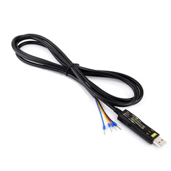
USB TO RS232/485 (C) is a USB to RS232/485 converter. With this converter, it is possible to connect the USB interface of a computer or other device to an RS232 or RS485 logic level device for data communication.
Features
- Adopts the original FT232RNL chip solution, it ensures high-speed communication that is stable, reliable and compatible
- Onboard TVS (Transient Voltage Suppressor), effectively suppresses surge voltage and transient spike voltage in the circuit, anti-electrostatic
- Onboard resettable fuse and ESD to prevent overcurrent, overvoltage, backflow and static electricity, enhancing shock resistance and ensuring stable and secure communication
- Onboard RS232/485 communication switching circuit, allows users to flexibly switch communication types by toggling the switch
- Onboard RS485 output terminal with a 120R resistor, which can be enabled by a toggle switch for flexible switching
- Onboard 3 LED indicators for easy monitoring of power and signal transmission status
- ABS environmental-friendly case, compact in size, portable and easy to use, cost-effective
Specifications
| Product type | USB to RS232/RS485 serial cable | |
| Host port | USB | |
| Device port | RS232 / RS485 (switchable) | |
| USB port | Interface type | USB-A interface |
| Interface protection | Resettable fuse, ESD protection | |
| RS232 interface | Interface type | 4PIN cable with female crimp connector |
| Interface protection | TVS tube, surge-suppress and ESD protection | |
| Transmission mode | Point-to-point | |
| Communication speed | 300 bps ~ 921,600bps | |
| RS485 interface | Interface type | 4PIN cable with female crimp connector |
| Interface protection | 200W lightningproof, surge-suppress and ESD protection | |
| Transmission mode | Point-to-multipoints (up to 32 nodes, it is recommended to use repeaters for 16 nodes or more) | |
| Communication speed | 300 bps ~ 921600bps | |
| Indicators | PWR | Red power indicator, lights up when connected to USB and the voltage is detected |
| TXD | Green TX indicator, lights up when data is sent through the USB port | |
| RXD | Blue RX indicator, lights up when the device ports send data back | |
| Cable specification | Black, PVC sheath, total length 2m | |
Interfaces
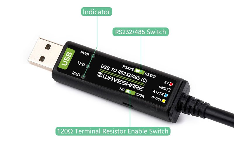
Pinout Definition

| 5V | Provides 5V to external device |
| GND | Signal ground |
| A+/TX | RS485 A+/RS232 TXD |
| B-/RX | RS485 B- / RS232 RXD |
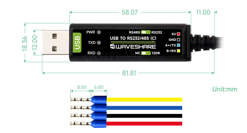
Dimensions
Driver Installation
USB Driver Installation
- Download the driver VCP Driver
- Double-click CDM212364_Setup.exe to install according to normal steps
- Click Extract, then click Next
- Click I accept this agreement, then click Next, and finally click Finish
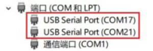
- When you connect your computer, you'll see an available port number in Device Manager
Hardware Test
Test environment: PC (Windows operating system)
Accessories required for the test:
- USB TO RS232/485 (C) x 1pcs
- USB TO RS232/485 x 1pcs
- USB cable type A male port to type A female port (or directly connected to the USB port of the computer)
- Cables
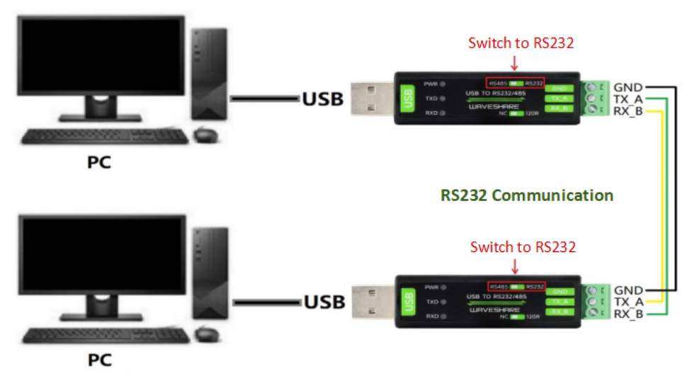
RS232 Test
- Dock the RS232 interface of the module, that is, staggered connection between RXD and TXD, connecting GND to GND, and switch the toggle switch on it to RS232. Refer to the following diagram for the connection:
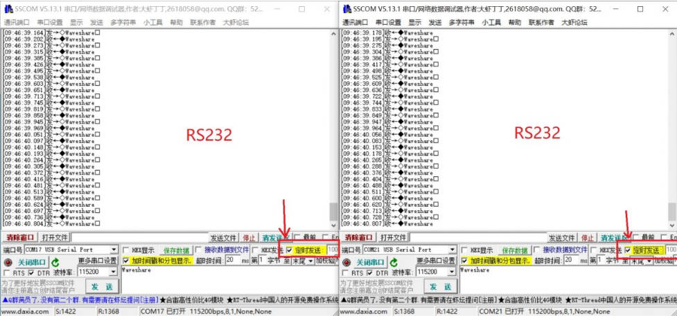
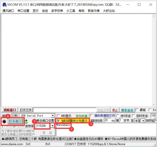
- Open 2 SSCOM serial assistant tools on the computer, open the corresponding port numbers

- Select the baud rate as 115200, input the characters to be sent, and choose Add time stamp and subpackage display for better results, then click Open serial port

- Click "Timed Send" in the 2 SSCOM windows, you can see that the 2 windows are sending and receiving data normally, and the test effect is shown in the following figure:
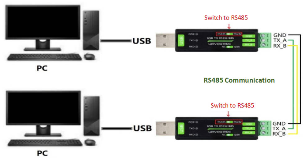
RS485 Test
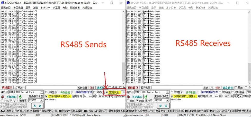
- Dock the RS485 interface of the module, that is, A+ --> A+, B- --> B-, GND --> GND, and switch the toggle switch on it to RS485. Refer to the following diagram for the connection:
- Open 2 SSCOM serial assistant tools on the computer, open the corresponding port numbers
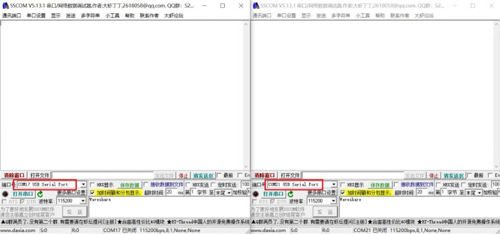
- Select the baud rate as 115200, input the characters to be sent, and choose Add time stamp and subpackage display for better results, then click Open serial port
- Click "Timed Send" with 100ms in the a SSCOM window, you can see that the 2 windows are sending and receiving data normally, and the test effect is shown in the following figure:
Resources
Datasheet
Software and Driver
- VCP Driver (Or download from FTDI official website, for other systems, please enter the FTDI official website to download the corresponding VCP driver)
- SSCOM debugging assistant
Support
Monday-Friday (9:30-6:30) Saturday (9:30-5:30)
Email: services01@spotpear.com
TAG:
Raspberry Pi Compute Module 4 CM4 IO Board Dual Gigabit Ethernet Mini Router Board
Programmable Keyboard
Raspberry Pi 12.3 inch DSI MIPI Display TouchScreen LCD 720x1920 Luckfox Lyra Omni3576 RK3576
ESP32 S3 Development Board 1.43 inch AMOLED Display 1.43inch TouchScreen For Arduino LVGL With SD-Port/ QMI8658C 6-Axis Sensor
Raspberry Pi Pico GNSS expansion board L76K GPS Beidou (BDS) GLONASS QZSS A-GNSS For RP2040/RP2350
X1300 X1300-A2 Raspberry Pi 5 HDMI to CSI-2 Shield 1080P@60fps & Audio & Video Also
Raspberry Pi USB Global Shutter Camera 1MP OV9281 120fps Black/White 120fps also For Jeston RDK
Core3566002032
RDK X5 PoE Module For Power Over Ethernet/ IEEE 802.3af/at PoE For D-Robotics RDK X5
Magnetic Encoder Servo Motor 120KG.CM 24V 360° RS485 High Precision And Large Torque
Screen
user guide
0.85inch LCD Button Mechanical Keyboard Display Screen 128x128 For Arduino /Raspberry Pi /ESP32 /RP2040 /STM32
Industrial Isolated USB TO 4CH RS485 (B) Converter UART CH344L For Wall/Rail-Mount
Raspberry Pi Pico 1.54inch LCD display 240×240 IPS 1.54 inch screen
DDSM400 Direct Drive Servo Motor All-In-One Design Hub Serial -LIN Bus Motor
360°
ESP32-S3 AI 1.54-inch (G) e-Paper Ink Screen 1.54inch Display AIoT Development Board Deepseek
Lidar
TOF Time-Of-Flight Laser Range Sensor Radar Module UART / I2C Port