



- sales/support
Google Chat:---
- sales
+86-0755-88291180
- sales01
sales@spotpear.com
- sales02
dragon_manager@163.com
- support
tech-support@spotpear.com
- CEO-Complaints
zhoujie@spotpear.com
- Only Tech-Support
WhatsApp:13246739196
- Purchase/Shipping/Refund
WhatsApp:13424403025
- HOME
- >
- ARTICLES
- >
- Common Moudle
- >
- ESP
ESP32-S31-Zero-N16R16 User Guide
Product Features
- The ESP32-S31 chip uses a 32-bit RISC-V dual-core processor with a clock speed of up to 320 MHz and built-in 512 KB SRAM.
- The chip integrates 2.4 GHz Wi-Fi 6, Bluetooth 5.4 (LE), Classic Bluetooth (BR/EDR), and IEEE 802.15.4, supporting Thread and Zigbee protocols; the current accompanying examples include Wi-Fi and BLE applications.
- The chip has 6 SPI interfaces, of which 2 are dedicated to PSRAM, 2 are dedicated to Flash, and 2 are general-purpose SPI, and also provides 1 low-power LP SPI.
- The chip has 2 I2C, 4 UART, 2 I2S, 2 12-bit SAR ADCs (up to 16 channels), and 2 DACs, and also provides 1 low-power LP I2C and LP UART each.
- Provides four storage combinations of 16 MB or 32 MB Flash and 16 MB or 32 MB PSRAM, corresponding to the N16R16, N32R16, N16R32, and N32R32 series respectively.
- Uses a castellated hole design, exposing 15 GPIOs, and can be soldered and integrated into a custom baseboard; a pre-soldered pin header version is also available.
- Equipped with either an onboard 2.4 GHz SMD antenna or an IPEX-4 external antenna connector, depending on the selected version.
- Integrates a 40 Pin expansion connector, which can connect RGB LCD, touchscreen, and SD card expansion devices.
- The USB Type-C interface connects to the chip's USB Serial/JTAG and can be used for program download and console communication.
- Onboard WS2812B-1010 RGB LED, as well as BOOT and RESET buttons.
- Comes with 12 ESP-IDF examples covering GPIO, RGB LED, button, UART, I2C, Wi-Fi, BLE, and peripheral tests such as display, touch, and SD card.
The peripheral counts are based on the pre-release version v0.5 of the ESP32-S31 Chip Datasheet and represent chip-level resources; the specific available signals depend on the board's exposed pins, pin multiplexing, and SDK support.
The accompanying examples use ESP-IDF v6.1. ESP32-S31 is a preview target and requires the --preview parameter. For version selection, environment setup, and build and flashing steps, see ESP32-S31-Zero ESP-IDF Development.
Resource Overview
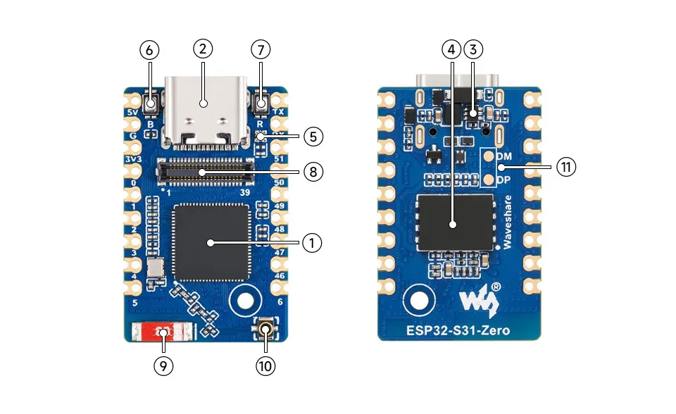
- ESP32-S31 Dual-Core Processor: Operating frequency up to 320 MHz.
- USB Type-C Interface: For power supply, program download, and debugging.
- MP1605GTF-Z DC-DC: Provides 3.3 V power.
- Flash Chip: Stores programs and data.
- WS2812 (LED): Programmable RGB indicator light.
- BOOT Button: Works with the reset button to enter download mode.
- RESET Button: Resets and restarts the development board.
- 40 Pin Board-to-Board Expansion Connector: For expanding RGB LCD, touchscreen, and SD card.
- SMD Antenna: For 2.4 GHz wireless communication; fitted only on the SMD antenna version.
- IPEX-4 Antenna Connector: Connects an external 2.4 GHz antenna; fitted only on the external antenna connector version.
- USB Host Solder Pads: Exposes the USB D+ and D− signals.
Pinout
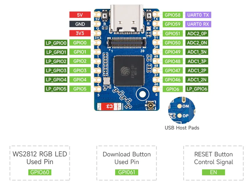
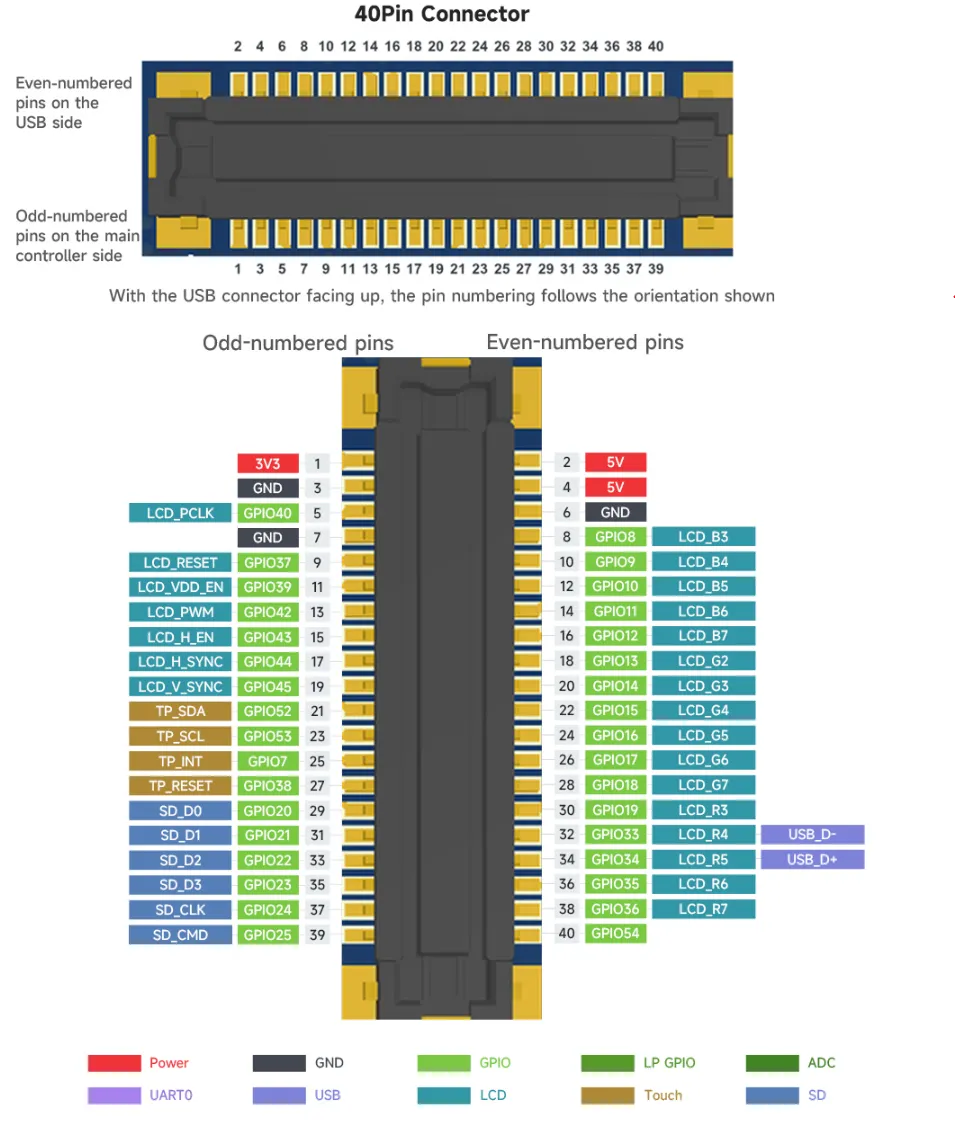
Antenna Versions
The development board uses either an onboard SMD antenna or an IPEX-4 external antenna connector, depending on the selected version. Keep the antenna area clear on the SMD antenna version; connect a suitable 2.4 GHz external antenna to the IPEX-4 version.
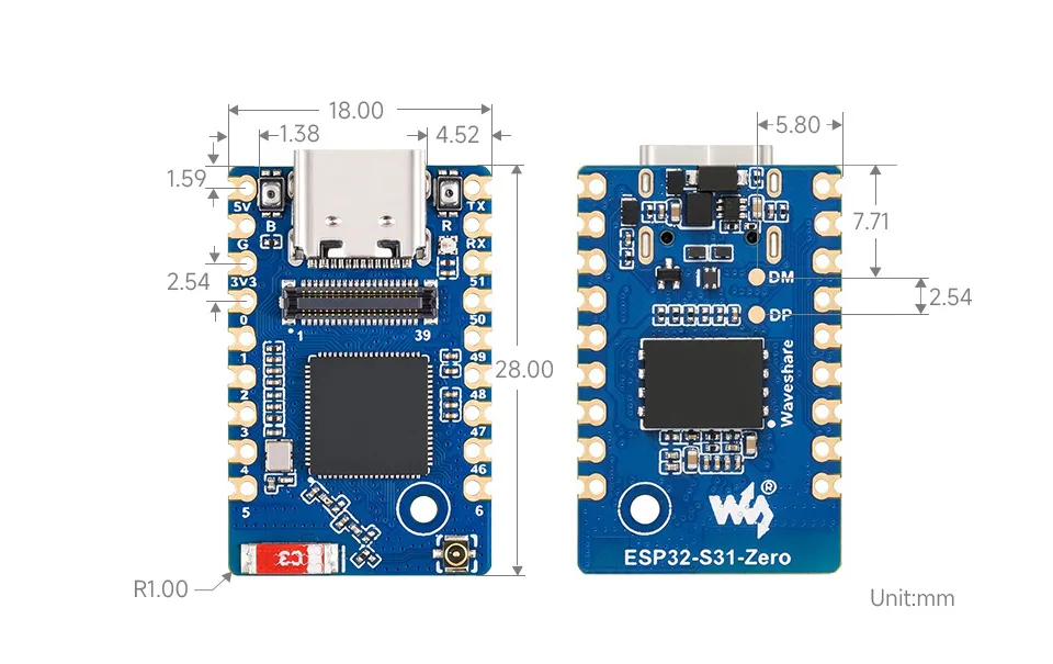
Product Dimensions
ESP-IDF
This chapter includes the following sections. Please read as needed:
ESP-IDF Getting Started
New to ESP32 ESP-IDF development and looking to get started quickly? We have prepared a general Getting Started Tutorial for you.
- Section 1: Environment Setup
- Section 2: Running Examples
- Section 3: Creating a Project
- Section 4: Using Components
- Section 5: Debugging
- Section 6: FreeRTOS
- Section 7: Peripherals
- Section 8: Wi-Fi Programming
- Section 9: BLE Programming
Please Note: This tutorial uses the ESP32-S3-Zero as a teaching example, and all hardware code is based on its pinout. Before you start, it is recommended that you check the pinout of your development board to ensure the pin configuration is correct.
Set Up the ESP-IDF Development Environment
Select the ESP-IDF Version
The accompanying examples use ESP-IDF v6.1 with the target chip esp32s31. Version numbers in the general installation screenshots below are for demonstration only.
The following guide uses Windows as an example, demonstrating development using VS Code + the ESP-IDF extension. macOS and Linux users should refer to the official documentation.
The screenshots in this section use ESP-IDF V5.5.2 as an example. When installing, please select the ESP-IDF version that matches your board's example.
Install the ESP-IDF Development Environment
Download the installation manager from the ESP-IDF Installation Manager page. This is Espressif's latest cross-platform installer. The following steps demonstrate how to use its offline installation feature.
Click the Offline Installer tab on the page, then select Windows as the operating system and the ESP-IDF version you need (the version shown in the screenshot is for reference only — choose the version that fits your actual needs).
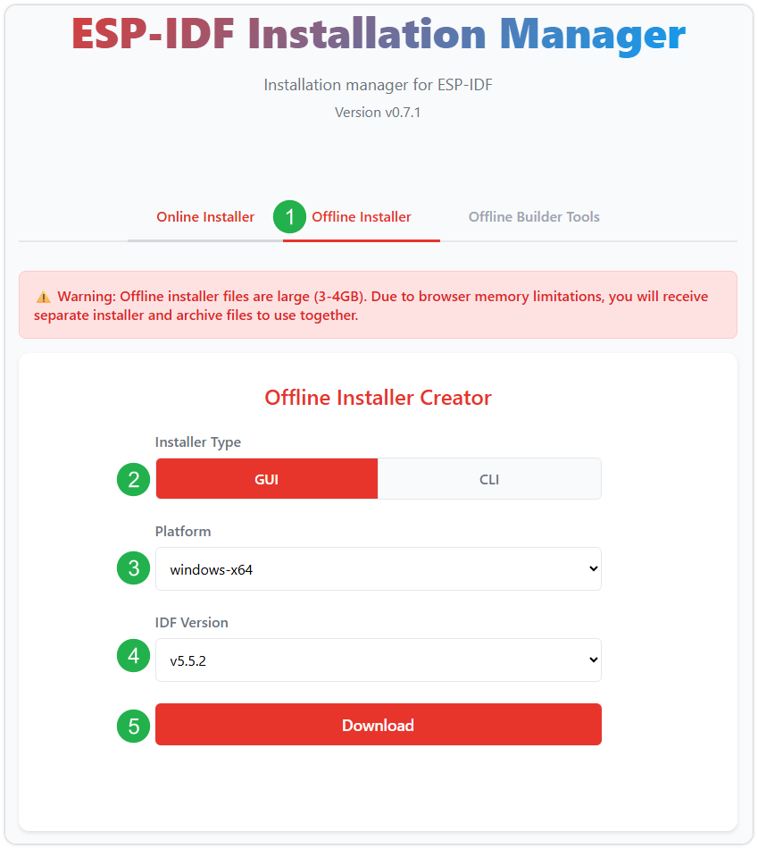
After confirming your selection, click the download button. The browser will automatically download two files: the ESP-IDF Offline Package (.zst) and the ESP-IDF Installer (.exe).
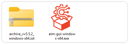
Please wait for both files to finish downloading.
Once the download is complete, double-click to run the ESP-IDF Installer (eim-gui-windows-x64.exe).
The installer will automatically detect if the offline package exists in the same directory. Click Install from archive.
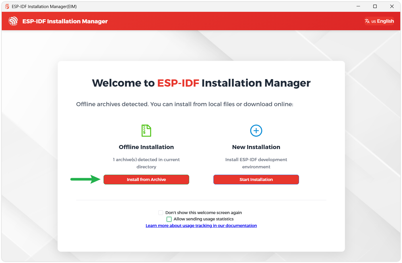
Next, select the installation path. We recommend using the default path. If you need to customize it, ensure the path does not contain Chinese characters or spaces. Click Start installation to proceed.
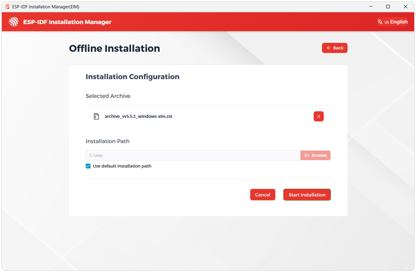
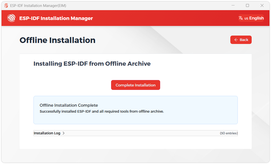
When you see the following screen, the ESP-IDF installation is successful.
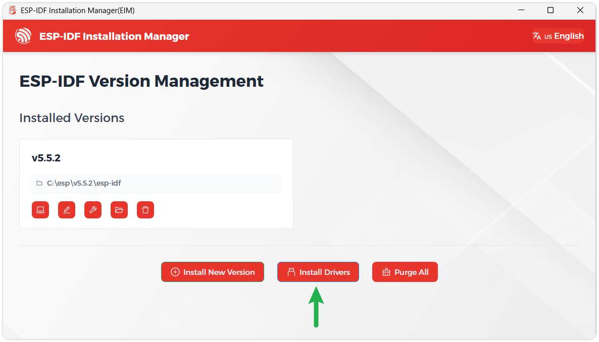
We recommend installing the drivers as well. Click Finish installation, then select Install driver.
Install Visual Studio Code and the ESP-IDF Extension
Download and install Visual Studio Code.
During installation, it is recommended to check Add "Open with Code" action to Windows Explorer file context menu to facilitate opening project folders quickly.
In VS Code, click the Extensions icon
 in the Activity Bar on the side (or use the shortcut Ctrl + Shift + X) to open the Extensions view.
Enter ESP-IDF in the search box, locate the ESP-IDF extension, and click Install.
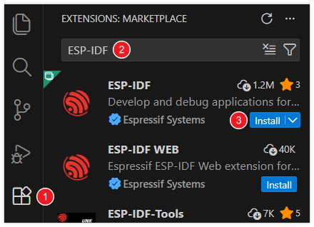
For ESP-IDF extension versions ≥ 2.0, the extension will automatically detect and recognize the ESP-IDF environment installed in the previous steps, requiring no manual configuration.
Download the ESP32-S31-Zero Example Programs and open the required example project directory in VS Code, such as examples/esp-idf/02_blink_rgb. For building, flashing, and serial monitoring, see ESP-IDF Getting Started: Run Example, using the version and target chip specified on this page.
Example Programs
Each example is an independent project. Example 11 requires the matching adapter boards and external devices; for bare-board getting started, you can run the RGB LED, chip info, or BOOT button examples first.
| Example Directory | Function | Additional Conditions |
|---|---|---|
| 01_gpio_output | Set the 15 exposed GPIOs to high level | Disconnect external output sources and loads |
| 02_blink_rgb | Control the onboard RGB LED | No external LED required |
| 03_chip_info | Print chip and Flash information | USB console |
| 04_boot_button | Read the BOOT button | USB console |
| 05_uart_loopback | UART1 transmit, receive, and compare | Jumper between GPIO58 and GPIO59 |
| 06_i2c_scan | Scan external I2C devices | External devices and appropriate pull-ups |
| 07_wifi_scan | Scan nearby Wi-Fi hotspots | Correct antenna path |
| 08_wifi_sta | Connect to a specified Wi-Fi hotspot | Correct antenna path and a 2.4 GHz hotspot |
| 09_wifi_ap | Create a Wi-Fi SoftAP | Correct antenna path and wireless terminals |
| 10_ble_advertiser | BLE advertising and connection events | Correct antenna path and a BLE debugging tool |
| 11_board_test | Comprehensive test | Matching touchscreen adapter board, SD card adapter board, and external devices |
| 12_wifi_performance | Wi-Fi throughput and link diagnostics | Correct antenna path and an iperf 2.x peer |
01_gpio_output: GPIO Output
Example Description
This example configures GPIO0-6, GPIO46-51, GPIO58, and GPIO59, for a total of 15 signals, as push-pull outputs and keeps them at high level.
Operation Steps
- Before running, disconnect the external output sources and loads on these pins to avoid signal conflicts.
- Build and download
01_gpio_output. - Use a multimeter or logic analyzer to check the levels relative to GND.
Expected Behavior
The listed pins should remain at high level without periodic toggling. The program does not perform loopback measurements; check each pin with a multimeter or logic analyzer. The serial log only indicates that the outputs have been configured.
02_blink_rgb: RGB LED
Example Description
This example uses the RMT peripheral through GPIO60 to send WS2812 data and control the onboard WS2812B-1010. The color data is sent in GRB order; it cannot be replaced by simply toggling the GPIO60 level.
Operation Steps
- Connect the development board through the Type-C interface; no external LED is required.
- Build and download
02_blink_rgb, and observe the onboard RGB LED.
Expected Behavior
The RGB LED cycles through red for 1 second, green for 1 second, blue for 1 second, and off for 0.5 second, then repeats. Check the actual colors, sequence, and duration.
03_chip_info: Chip Information
Example Description
This example reads and prints the target name, number of CPU cores, chip revision number, base MAC address, feature bits, and Flash information.
Operation Steps
Build and download 03_chip_info, open the USB console, and record the chip information and Flash read results.
Expected Behavior
The console outputs the chip information, with emphasis on distinguishing two Flash outputs:
Physical Flash: The physical capacity read throughesp_flash_get_physical_size().Configured flash size: The Flash capacity set in the project.
The two values may differ. The schematic indicates a 32 MiB device, while the project retains a 16 MiB configuration; the actual result is subject to the read value of the development board in use.
04_boot_button: BOOT Button
Example Description
This example configures GPIO61 as a pull-up input, reads the active-low BOOT button, and confirms the level change through a delay.
Notes
Release BOOT during normal startup. Holding BOOT while resetting selects download mode, in which case the normal running flow of the button example will not be entered.
Operation Steps
- Build and download
04_boot_button, and open the USB console. - After the program runs, press and release BOOT, and observe the log.
Expected Behavior
The serial port outputs Button PRESSED or Button RELEASED according to the state change.
05_uart_loopback: UART Loopback
Example Description
The program uses UART1 to send a numbered string through GPIO58 (TX), which is looped back to GPIO59 (RX) via a jumper and compared byte by byte after reception. The UART configuration is as follows:
| Parameter | Setting |
|---|---|
| UART | UART1 |
| Baud Rate | 115200 |
| Data Format | 8 data bits, no parity, 1 stop bit, no hardware flow control |
Operation Steps
- Power off and disconnect other external devices on GPIO58 and GPIO59.
- Short pin 2 GPIO58 (UART1 TX) of H2 to pin 1 GPIO59 (UART1 RX).
- After powering on, build and download
05_uart_loopback, and open the USB console. There is no need to connect UART1 to the computer.
Expected Behavior
When the received data length and content both match, it outputs PASS; otherwise, it outputs FAIL and prompts to check the jumper.
06_i2c_scan: I2C Scan
Example Description
The program scans 0x08 - 0x77 each round and outputs the address table and device count. The external device wiring is as follows:
| Signal | GPIO | Interface |
|---|---|---|
| SDA | GPIO52 | Pin 21 of J2 |
| SCL | GPIO53 | Pin 23 of J2 |
The relevant external pull-up resistors in the schematic are marked as not-populated options; appropriate 3.3 V pull-ups should be provided according to the peripheral and bus requirements.
Operation Steps
- After powering off, connect an external I2C device suitable for 3.3 V logic levels according to the table above, and confirm common ground and the SDA and SCL pull-up conditions.
- After powering on, build and download
06_i2c_scan, and open the USB console.
Expected Behavior
An address indicates a responding device, -- indicates no response received, and UU indicates a probe timeout. Displaying 0 devices when no device is connected can be a normal result; do not assume that there is an I2C slave device with a fixed address on the board.
07_wifi_scan: Wi-Fi Scan
Example Description
The program uses STA mode to scan for hotspots, printing the total number of hotspots each round, displaying up to 20 records, including channel, RSSI, authentication mode, and SSID.
Operation Steps
- Confirm the antenna version of the development board: keep the antenna area clear on the SMD antenna version; connect a suitable 2.4 GHz external antenna to the IPEX-4 version.
- Build and download
07_wifi_scan, and open the USB console to view the scan results.
Expected Behavior
After each round is complete, it delays 10 seconds before scanning again. The scan results are affected by surrounding hotspots, the antenna, and the environment.
08_wifi_sta: Connect to Wi-Fi
Example Description
This example connects to a specified 2.4 GHz Wi-Fi hotspot and outputs the connection status and the obtained IPv4 address.
Operation Steps
Confirm the antenna path, open menuconfig of the 08_wifi_sta project, and set the following in "Example Configuration":
- "Wi-Fi SSID": The name of the 2.4 GHz hotspot to connect to.
- "Wi-Fi password": The hotspot password.
- "Maximum connection retries": The maximum number of retries.
Save the configuration, rebuild and download 08_wifi_sta, and open the USB console.
Expected Behavior
After obtaining the IPv4 address, the program outputs IPv4 address:; if the connection fails, it retries according to the configuration and outputs a failure message after reaching the maximum number of retries.
This example only demonstrates hotspot connection and address acquisition. Remove local Wi-Fi credentials before sharing the project or screenshots.
09_wifi_ap: Create a SoftAP
Example Description
This example creates a local SoftAP and does not implement internet sharing or NAT routing. The example allows an open network with an empty password, which should be set according to actual needs during use.
Operation Steps
- Confirm the antenna path and open
menuconfigof the09_wifi_approject. - Configure the SoftAP name, password, channel, and maximum number of connections in "Example Configuration".
- Save the configuration, rebuild and download
09_wifi_ap. - Connect to the configured hotspot through a computer or phone, and observe the USB console.
Expected Behavior
The console records terminal join and leave events. When the terminal prompts that there is no internet connection, judge the result based on the local connection status.
10_ble_advertiser: BLE Advertising
Example Description
This example uses NimBLE and advertises the device name ESP32-S31-Zero. This example does not define a serial passthrough service and cannot be used as a Bluetooth serial example.
Operation Steps
- Confirm the antenna path, build and download
10_ble_advertiser. - Use a tool that supports BLE scanning to find
ESP32-S31-Zero. - Connect to the device and then disconnect, and observe the connection status in the USB console.
Expected Behavior
The program outputs logs on connection and disconnection, and resumes advertising after a connection failure or disconnection.
11_board_test: Comprehensive Test
Example Description
This project includes tests for Flash, PSRAM, CPU/RAM, the GPIO60 RGB LED, as well as external display, touch, SD, and the GPIO54 indicator light. The display, touch, and SD card tests require connecting the matching touchscreen adapter board, SD card adapter board, and external devices. The GPIO54 indicator light must be connected externally; this indicator is not fitted on the development board.
Hardware Conditions
Before running, check the adapter boards, external devices, pins, and power supply according to the table below. The complete compatibility of the supporting hardware still needs to be verified on the actual board; when no display, touchscreen, or SD card is connected, the failure results of the corresponding items cannot be used to determine a bare-board fault.
| Item | Current Project Settings and Scope |
|---|---|
| LCD | External 800 × 480 RGB565 display, pixel clock 16 MHz; this is a project configuration, not a bare-board display specification |
| Touch | External GT911, using GPIO52, GPIO53, GPIO38, and GPIO7; probes 0x14 and 0x5D at startup |
| Continuous touch tracking | Disabled by default, with detection only at startup; continuous sampling has previously encountered communication failures, and stability has not yet been confirmed |
| SD | External card slot, GPIO20-25, 4-bit SDMMC, runtime clock configured to 20 MHz |
The automatic test erases and writes the first 4 KiB sector of the dedicated testdata partition, and the SD test creates, reads back, and deletes temporary files. Confirm the partition usage and back up data before running. After the LCD starts, GPIO33 and GPIO34 are changed to RGB data lines, and the USB Serial/JTAG console becomes unavailable; the interactive console is retained only when display startup fails and pin takeover is not completed.
Operation Steps
- After powering off, connect the confirmed matching adapter boards and external devices according to the project pin and power supply requirements, confirm the partition usage, and back up data.
- Check the PSRAM, display, touch, and SD configurations of
11_board_test. - Keep continuous touch sampling disabled. To troubleshoot touch communication, enable sampling and touch markers in "Board test" > "Enable continuous touch sampling and touch marker".
- After confirming the hardware conditions, build and download
11_board_test, and check the logs and peripheral behavior according to the test items.
Result Judgment
The stability of continuous touch tracking has not yet been confirmed; successful startup detection alone does not establish that continuous tracking works correctly. After the LCD starts successfully, the USB console can no longer be used to observe logs. Check the display, touch, and SD card individually and confirm each result.
12_wifi_performance: Wi-Fi Throughput Test
Example Description
This example provides a USB Serial/JTAG console for Wi-Fi connection, link information, ping, and TCP and UDP throughput tests.
Preparation and Operation
Confirm the antenna path and prepare a computer running iperf 2.x; the iperf3 protocol is not compatible with this example. Build and download 12_wifi_performance, and open the USB console.
After downloading and starting, enter help in the wifi-perf> console to view the commands. The STA mode connection commands are as follows; replace the content in angle brackets with local parameters:
sta_connect <SSID> <PASSWORD>
rf_info
ping <GATEWAY_IP>
For throughput testing, the receiving end must be started first. In the table below, <PC_IP> is the computer address, and <DUT_IP> is the development board address.
| Direction | Computer-Side Command | Development Board Console Command |
|---|---|---|
| TCP, development board sends | iperf -s -i 1 | iperf -c <PC_IP> -i 1 -t 60 |
| TCP, development board receives | iperf -c <DUT_IP> -i 1 -t 60 | iperf -s -i 1 |
| UDP, development board sends | iperf -s -u -i 1 | iperf -c <PC_IP> -u -b 20M -i 1 -t 60 |
| UDP, development board receives | iperf -c <DUT_IP> -u -b 20M -i 1 -t 60 | iperf -s -u -i 1 |
Connecting the computer to the test router through a wired network can reduce the impact of the computer's own wireless link on the test. Record the antenna, power supply, channel, bandwidth, direction, RSSI, throughput, and UDP packet loss; do not preset the result to a fixed rate.
Result Judgment
The transmit power field in rf_info is a software configuration value, not a measured RF power. This example is only for function and throughput testing.
ESP32-S31-Zero Firmware Flashing and Erasing
ESP32-S31-Zero provides factory firmware V1 (2026-10-20) to restore the factory demo. The firmware file is in the firmware/ directory of the accompanying repository:
| Item | Details |
|---|---|
| Firmware File | ESP32-S31-Zero_FactoryOnly_20261020.bin |
| Flash Address | 0x00 |
| Download Interface | Type-C, USB Serial/JTAG |
Erasing the entire Flash deletes the firmware, settings, and data on the device. Flashing firmware also overwrites the target region. Back up any content that needs to be retained before proceeding.
The flashing tool must explicitly support esp32s31. Do not select esp32s3. To enter download mode manually:
- Hold down BOOT.
- While holding BOOT, press and release RESET.
- Release BOOT.
After flashing, press RESET to run the firmware.
- Firmware Flashing
- Firmware Erasing
The following steps apply to the firmware provided on this page.
Download and extract Espressif's official Flash Download Tool (Download)
Run Flash Download Tool and select the options that match the development board's MCU and download interface. The screenshot below uses ESP32-S3 and USB as an example; use the options required by the product's hardware design.
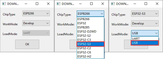
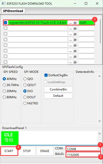
Parameter settings
- Select the COM port for the development board
- Set BAUD to the maximum value, 1152000
- Click the "..." button in the row, select the bin file provided by Waveshare, manually enter the flash address given at the top of this page in the field to its right, and select the leftmost checkbox in the row
- Click START to begin flashing
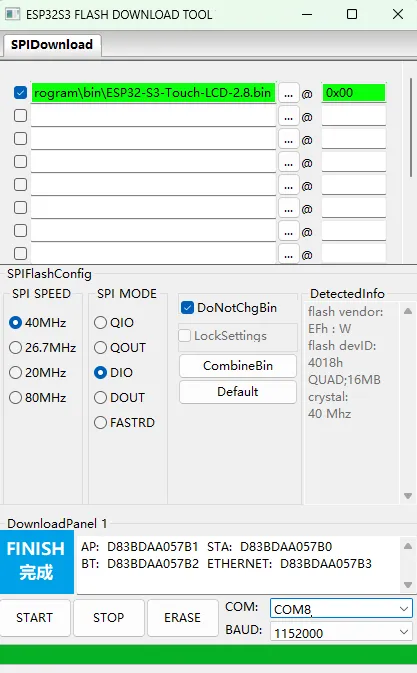
Wait for flashing to complete (this may take some time; please be patient)
Press the reset button and verify the result
Resources and Documents
1. Example Programs
2. Hardware Resources
3. Technical Manuals
4. Software Tools
5. Other Resources
Support
Monday-Friday (9:30-6:30) Saturday (9:30-5:30)
Email: services01@spotpear.com
[Tutorial Navigation]
- Product Features
- Resource Overview
- Pinout
- Antenna Versions
- Product Dimensions
- ESP-IDF
- ESP-IDF Getting Started
- Set Up the ESP-IDF Development Environment
- Select the ESP-IDF Version
- Install the ESP-IDF Development Environment
- Install Visual Studio Code and the ESP-IDF Extension
- Example Programs
- 01_gpio_output: GPIO Output
- 02_blink_rgb: RGB LED
- 03_chip_info: Chip Information
- 04_boot_button: BOOT Button
- 05_uart_loopback: UART Loopback
- 06_i2c_scan: I2C Scan
- 07_wifi_scan: Wi-Fi Scan
- 08_wifi_sta: Connect to Wi-Fi
- 09_wifi_ap: Create a SoftAP
- 10_ble_advertiser: BLE Advertising
- 11_board_test: Comprehensive Test
- 12_wifi_performance: Wi-Fi Throughput Test
- ESP32-S31-Zero Firmware Flashing and Erasing
- Resources and Documents
- 1. Example Programs
- 2. Hardware Resources
- 3. Technical Manuals
- 4. Software Tools
- 5. Other Resources
- Support